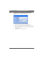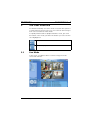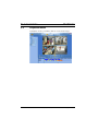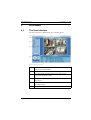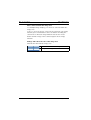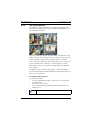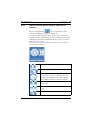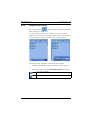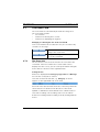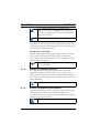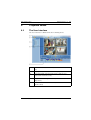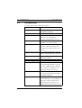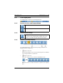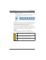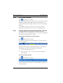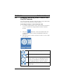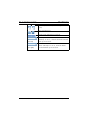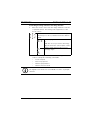
1
DiBos/DiBos Micro
en
Operation Manual
DiBos/DiBos Micro
Table of Contents | en
3
Table of Contents
1
Program Start/Login
7
1.1
Starting the Program
7
1.2
Logging on to the System
7
1.2.1
Logging on to the System (Standard)
7
1.2.2
Logging on to the System with LDAP Access
8
2
The User Interface
9
2.1
Live Mode
2.2
Playback Mode
10
3
Live Mode
11
3.1
The User Interface
11
3.2
The Menu Bar
12
3.3
The Display Bar
14
3.3.1
Buttons for Live and Playback Mode
14
3.3.2
Button for Full Image
14
3.3.3
Buttons for Image Display
14
3.3.4
Button for Camera Round
16
3.3.5
Button for Switching the Sound On and Off
16
3.4
The Device List
17
3.5
The Image Area
19
3.5.1
The Image Area Layout
19
3.5.2
The Image Window
21
3.6
The Control and Status Field
24
9
3.6.1
Control field for Dome Cameras and Pan/Tilt Cameras
25
3.6.2
Displaying the Relays
27
3.6.3
Displaying the Alarm Inputs
28
3.6.4
Instant Playback
29
3.6.5
Control Field for Monitors
31
3.7
The Event Field
33
3.7.1
The Event List
33
3.7.2
Button for Filtering the Events
34
3.7.3
Button for Displaying the Logbook
34
Bosch Sicherheitssysteme GmbH
Operation Manual
F.01U.033.372 | V5 | 2009.09
4
en | Table of Contents
DiBos/DiBos Micro
4
Playback Mode
35
4.1
The User Interface
35
4.2
The Menu Bar
36
4.3
The Display Bar
41
4.3.1
Buttons for Live and Playback Mode
41
4.3.2
Button for Full Image
41
4.3.3
Buttons for Image Display
41
4.3.4
Button for Camera Round
43
4.3.5
Button for Switching the Sound On and Off
43
4.4
The Device List
44
4.5
The Image Area
46
4.5.1
Image Area Layout
46
4.5.2
The Image Window
48
4.6
The Timeline Area
50
4.6.1
Camera List with Timeline/List of Search Results
52
4.6.2
Camera List with Timeline
52
4.6.3
List of Search Results
54
4.6.4
Timeline Measuring Unit/Search Results Title Bar
54
4.6.5
Date and Time
55
4.6.6
Searching for a Previous or Next Event
55
4.6.7
The Recorder Buttons
56
4.6.8
Reducing the Size of/Enlarging the Timeline Area
57
4.6.9
Changing the Playback Speed
58
4.6.10
Calling up the Search Functions
59
4.6.11
Exporting Image Data
60
5
Operation - Live/Playback Mode
61
5.1
Displaying Incoming Alarms
61
5.1.1
Non-automatic Display of Incoming Alarms
61
5.1.2
Automatic Display of Incoming Alarms
62
5.2
Automatic Alarm Recording
63
5.3
Creating/Editing Favorites
64
5.4
Displaying the Logbook
66
5.5
Starting/Exiting a Camera Round
68
5.6
Logging Off/Changing User
68
F.01U.033.372 | V5 | 2009.09
Operation Manual
Bosch Sicherheitssysteme GmbH
DiBos/DiBos Micro
Table of Contents | en
5
6
Operation - Live Mode
69
6.1
Filtering the Event List
69
6.2
Zooming/Controlling Dome Cameras and Pan/Tilt Cameras
71
7
Operation - Playback Mode
74
7.1
Searching for Date and Time
74
7.2
Searching for Events
74
7.3
Searching for Motion
76
7.4
Searching for Additional Data
78
7.5
Authenticating Images from Several Cameras
80
7.6
Authenticating a Single Image
80
7.7
Exporting Files
81
7.8
Showing Exported Files
83
7.9
Protecting Video
84
7.10
Removing the Protection from a Recording
85
7.11
Deleting a Video
86
8
The Icon Overview
87
Bosch Sicherheitssysteme GmbH
Operation Manual
F.01U.033.372 | V5 | 2009.09
6
en | Table of Contents
F.01U.033.372 | V5 | 2009.09
DiBos/DiBos Micro
Operation Manual
Bosch Sicherheitssysteme GmbH
DiBos/DiBos Micro
Program Start/Login | en
1
Program Start/Login
1.1
Starting the Program
7
When installation is complete, you can start the program.
1.
Switch on the computer and wait until the desktop
2.
Double-click the DiBos icon on your desktop or select Start
interface appears.
- Programs - DiBos. The computer starts the program and
displays the login dialog box.
1.2
Logging on to the System
When the program has started, the dialog box for logging on to
the system appears. The dialog box will have a different
appearance, depending on whether you have logged on with or
without LDAP access.
1.2.1
Logging on to the System (Standard)
For systems that are not connected to an LDAP server, only the
name and password will be required.
1.
Enter your user ID in the name input field.
2.
Enter your password in the password input field.
3.
Click OK. You are now in live mode.
Bosch Sicherheitssysteme GmbH
Operation Manual
F.01U.033.372 | V5 | 2009.09
8
en | Program Start/Login
1.2.2
DiBos/DiBos Micro
Logging on to the System with LDAP Access
For systems that are connected to an LDAP server, an
additional selection field will be displayed.
1.
Enter your user ID in the name input field.
2.
Enter your password in the password input field.
3.
Click the down arrow and select the LDAP server if you
wish to log on via LDAP. To log on locally, the local system
must be selected.
4.
Click OK. You are now in live mode.
F.01U.033.372 | V5 | 2009.09
Operation Manual
Bosch Sicherheitssysteme GmbH
DiBos/DiBos Micro
2
The User Interface | en
9
The User Interface
You will automatically access live mode every time the system is
re-started and every time you log on. You can look at live images
from selected cameras in this mode.
To rapidly switch between playback and live mode, just click
the button of the mode you want. The button you select is then
color-highlighted.
Button for live mode
Button for playback mode
2.1
Live Mode
In live mode, you will be able to view live images from the
connected cameras.
Bosch Sicherheitssysteme GmbH
Operation Manual
F.01U.033.372 | V5 | 2009.09
10
en | The User Interface
2.2
DiBos/DiBos Micro
Playback Mode
In playback mode, you will be able to view saved images.
F.01U.033.372 | V5 | 2009.09
Operation Manual
Bosch Sicherheitssysteme GmbH
DiBos/DiBos Micro
Live Mode | en
3
Live Mode
3.1
The User Interface
11
The user interface is divided into the following areas:
1
Menu bar with current date and time (see
Section 3.2 The Menu Bar)
2
Display bar (see Section 3.3 The Display Bar)
3
Device list with cameras and remote stations (see
Section 3.4 The Device List)
4
Image area with image windows (see Section 3.5 The
Image Area)
5
Control and status field (see Section 3.6 The Control
and Status Field)
6
Event field (see Section 3.7 The Event Field)
Bosch Sicherheitssysteme GmbH
Operation Manual
F.01U.033.372 | V5 | 2009.09
12
en | Live Mode
3.2
DiBos/DiBos Micro
The Menu Bar
The menu bar has the following functions:
System
Configuration wizard
Helps you to create a basic system
configuration quickly.
Configuration
Displays the configuration.
Database information
Displays information on the
cameras, e.g. free and used
memory, average image size etc. It
is displayed for the local system
and for configured and connected
remote stations.
Logbook
Displays specific events for local
systems or a remote station.
Log off/Change user
Logs the user off the system. The
system continues running in the
background. A different user can
log on.
Changing the password
The existing password is changed
when a new password is entered.
Exit
Exits the program (administrator
rights necessary).
Selected image window
Save image
Saves the image displayed in the
selected image window. It can be
saved as an HTML, BMP, JPG, GIF,
TIF or PNG file. If it is saved as a
HTML file, the additional data is
also saved.
F.01U.033.372 | V5 | 2009.09
Operation Manual
Bosch Sicherheitssysteme GmbH
DiBos/DiBos Micro
Print image
Live Mode | en
13
Prints the image displayed in the
selected image window (including
the additional data).
Motion data
Shows the areas where a motion
was detected in the selected image
window. To hide it, repeat the
command.
Note: It is only possible to search
for motion with locally connected
cameras.
View
Large icons
Displays the icons in the device list
in large format. To reduce their
size, repeat the command.
Large image area
Enlarges the image area and
reduces the size of the event field.
To reduce the size of the image
area, select the command again.
Large device list
Enlarges the device list and
reduces the size of the control and
status fields. To reduce the size of
the device list, select the command
again.
Display local time
Shows the actual recording date
and recording time of the device to
which the cameras are connected.
?
Help
Displays online help.
Info
Displays system information.
Bosch Sicherheitssysteme GmbH
Operation Manual
F.01U.033.372 | V5 | 2009.09
14
en | Live Mode
3.3
DiBos/DiBos Micro
The Display Bar
The display bar contains the following buttons:
3.3.1
Buttons for Live and Playback Mode
Button for live mode
Button for playback mode
3.3.2
Button for Full Image
Enlarges the image area to full image size.
To return to the original image display, press the
ESC key or double-click the right mouse button.
3.3.3
Buttons for Image Display
The individual buttons show how many image windows are
displayed in the image area.
–
Aspect ratio 4:3
When these buttons are selected, the image area is divided
into image windows of equal size.
–
Aspect ratio 4:3
Click the down arrow to show the individual views.
Note: The most recently used view is copied to the display
bar.
F.01U.033.372 | V5 | 2009.09
Operation Manual
Bosch Sicherheitssysteme GmbH
DiBos/DiBos Micro
Live Mode | en
–
15
Aspect ratio 16:9
This button allows you to optimize the image area for widescreen displays. Click the down arrow to show the
individual views.
Note: The most recently used view is copied to the display
bar.
1 image window is selected in every display you select. The
display you select appears with a yellow border. The image
from the camera which you select from the device list by
double-clicking is shown in this image window.
The number to the right beneath the button shows the user
how often he has already clicked this button. This number also
shows which cameras have been selected or which cameras will
be selected the next time the user clicks this button.
Example:
With 12 cameras and 2x 2-image windows this means:
You can click the button three times to display all cameras.
Cameras 1 to 4 are displayed (the number "1"
appears on the right beneath the button).
Cameras 5 to 8 are displayed (the number "2"
appears on the right beneath the button).
Cameras 9 to 12 are displayed (the number "3"
appears on the right beneath the button).
Bosch Sicherheitssysteme GmbH
Operation Manual
F.01U.033.372 | V5 | 2009.09
16
en | Live Mode
3.3.4
DiBos/DiBos Micro
Button for Camera Round
A dialog box opens after the button is clicked. Enter
the time after which the system will switch from
one camera to the next. With a camera round, all
cameras selected in the image area are displayed
one after the other.
Note: Clicking the button again ends the camera
round.
3.3.5
Button for Switching the Sound On and Off
Clicking this button switches the sound
on or off.
To adjust the volume, click the down
arrow.
Select the volume you require with the
volume control.
F.01U.033.372 | V5 | 2009.09
Operation Manual
Bosch Sicherheitssysteme GmbH
DiBos/DiBos Micro
3.4
Live Mode | en
17
The Device List
The device list is located on the left-hand side of the screen.
Depending on what is selected, the following are displayed:
–
Configured cameras and/or DiBos devices
–
Favorites view
–
Incoming alarms.
Configured cameras and/or DiBos devices
All locally connected cameras are listed.
If remote stations have been configured, they are listed along
with the cameras connected to them.
Network remote stations are automatically connected to the
local system.
–
DiBos device (localhost or remote station)
Right-click the icon to call up the following commands:
Connect
Creates the connection to the DiBos device.
Disconnect
Disconnects the connection to the DiBos device. The
DiBos device remains disconnected (even after a reboot),
until it is reconnected manually.
RAS remote stations must likewise be connected manually.
Configuration
With localhost: the default configuration opens.
With remote stations: the configuration opens in remote
mode.
Display all cameras
Displays all the DiBos device cameras in the image area.
Bosch Sicherheitssysteme GmbH
Operation Manual
F.01U.033.372 | V5 | 2009.09
18
en | Live Mode
DiBos/DiBos Micro
Favorites view
Favorites which have been saved are listed and can be called up
by double-clicking the icon. New favorites can be created.
Note: Favorites are a number of cameras that are displayed in a
specific way, e.g. cameras 1 - 4 in the 2x2 image window view.
Incoming alarms
The icon flashes red after alarms have been received in the
system. It is only displayed if there are alarms in the system.
Automatic display of alarm cameras
Automatic display of alarm cameras can be configured.
The
tab flashes red and the alarm cameras are
displayed. An audio signal sounds, if this has been configured.
Automatic alarm recording
Incoming alarms can be recorded automatically (standard) or
manually on the recipient. The selection is made in the
configuration. In both cases, all the cameras that are assigned
to the alarm in the device list are displayed. Recording takes
place without audio.
The
tab flashes red.
Enlarging and Reducing the Size of the Device List
Click the bar between the device list and the control and status
field.
Reduces the size of the device list
Enlarges the device list
NOTICE!
For icons shown in the device list, see Section 8 The Icon
Overview.
F.01U.033.372 | V5 | 2009.09
Operation Manual
Bosch Sicherheitssysteme GmbH
DiBos/DiBos Micro
3.5
Live Mode | en
19
The Image Area
The middle of the screen is where live images are displayed.
Arrange this area to suit your requirements.
3.5.1
The Image Area Layout
Specify the number and layout of image windows in the image
area
In the display bar, you can specify what the image area looks
like, i.e. the number and layout of the image windows
(see Section 3.3.3 Buttons for Image Display).
Place individual cameras in the image area
After selecting the image display, you will now want to display
specific cameras.
You can do so as follows:
–
Double-clicking
Double-clicking a camera icon in the device list places the
camera in the selected image window (with the yellow
border).
Left-click with the mouse to select a different image
window. Double-clicking a different camera icon places its
image in the new image window that you have just
selected.
–
"Drag and Drop"
Press and hold the left mouse button and drag the camera
icon from the device list into an image window. Release
the mouse button and the image of this camera appears in
the image window.
NOTICE!
In the image area, each camera can only be displayed once.
Bosch Sicherheitssysteme GmbH
Operation Manual
F.01U.033.372 | V5 | 2009.09
20
en | Live Mode
DiBos/DiBos Micro
Move cameras within the image area
In a multiple-image display, you can move cameras within the
image area.
To do so, move the mouse cursor into the title bar of an image
window, press and hold the left mouse button and drag the
camera into a different image window. Release the mouse
button and the image of this camera appears in the image
window.
Enlarge and reduce the size of the image area
Click the bar beneath the image area.
Reduces the size of the image area.
Enlarges the image area.
F.01U.033.372 | V5 | 2009.09
Operation Manual
Bosch Sicherheitssysteme GmbH
DiBos/DiBos Micro
3.5.2
Live Mode | en
21
The Image Window
Depending on which button is selected in the display bar for
the image area layout, the image area will be divided into one or
several image windows.
The selected image window appears with a yellow border. The
image from the camera which you select from the device list by
double-clicking is shown in this image window. If an audio
source has been assigned to the camera, this is also selected. If
a user is authorized to view live or saved images, he is also
authorized to listen to an audio recording which accompanies
these images.
In addition to the camera image display, each image window
has a title bar with information and buttons about the image, as
well as a zoom function.
The image window title bar
The title bar contains
–
an icon describing the type of camera (see Section 8 The
Icon Overview)
–
the name of the camera
–
an icon which indicates whether the image also has an
audio source
Camera with audio source
Bosch Sicherheitssysteme GmbH
Operation Manual
F.01U.033.372 | V5 | 2009.09
22
en | Live Mode
–
DiBos/DiBos Micro
an icon which displays the motion in the sensitive area of
the image
The system recognizes a motion in the sensitive
area of the image.
Note: This will only be displayed if the sensor
technology is activated in the camera's
configuration.
–
Buttons for enlarging, reducing the size of and de-selecting
the image.
The image window is enlarged so that it fills the
entire image area.
The image window is reduced to its original size.
The camera is de-selected. No camera image is
displayed. The image window is blue.
NOTICE!
Dome cameras and pan/tilt cameras can be controlled in the
image window.
F.01U.033.372 | V5 | 2009.09
Operation Manual
Bosch Sicherheitssysteme GmbH
DiBos/DiBos Micro
Live Mode | en
23
Image window zoom function
Every single image window has a zoom function. To use this
function, move your mouse cursor into an image window. The
mouse cursor now changes from an arrow into a magnifying
glass.
Using the zoom function with fixed cameras:
Left-click or scroll with the mouse wheel. The
image is digitally zoomed. In order to show that an
image has been zoomed, a magnifying glass is
shown in the bottom right-hand corner of the
image window.
Right-click or scroll with the mouse wheel. The
image is reset to the original size. The magnifying
glass in the bottom right-hand corner of the image
window disappears.
Note: The part of the image where the magnifying
glass is located is zoomed.
Zooming with dome cameras and pan/tilt
cameras:
Dome and pan/tilt cameras can be zoomed in the
image window using their own control functions.
To do this, move the cursor into the middle of the
image window until a magnifying glass appears
with a plus or minus sign. Left click with the
mouse or scroll with the mouse wheel to enlarge
or minimize the area.
Bosch Sicherheitssysteme GmbH
Operation Manual
F.01U.033.372 | V5 | 2009.09
24
en | Live Mode
3.6
DiBos/DiBos Micro
The Control and Status Field
A selection is made by clicking the buttons
The control field for dome cameras and pan/tilt
cameras is displayed (see Section 3.6.1 Control
field for Dome Cameras and Pan/Tilt Cameras).
The configured relays are displayed (see
Section 3.6.2 Displaying the Relays).
The configured alarm inputs are displayed (see
Section 3.6.3 Displaying the Alarm Inputs).
Instant playback is started (see
Section 3.6.4 Instant Playback).
The control field for monitors is displayed (see
Section 3.6.5 Control Field for Monitors).
Displays hidden icons.
F.01U.033.372 | V5 | 2009.09
Operation Manual
Bosch Sicherheitssysteme GmbH
DiBos/DiBos Micro
3.6.1
Live Mode | en
25
Control field for Dome Cameras and Pan/Tilt
Cameras
After selecting this tab
, the control field for dome
cameras and pan/tilt cameras is displayed.
The control field will not be active until a dome camera and
pan/tilt camera is displayed in the selected image window. The
individual elements are highlighted when you move over them
with the mouse cursor.
If no dome camera or pan/tilt camera has been selected, the
control field is inactive.
Pan the camera to the left/right.
Pan the camera up/down.
Pans the camera in all directions. Move the
mouse cursor to the icon and drag it in the
direction you would like to pan the camera
while holding down the left mouse button.
Enlarges (wide angle)/reduces (tele) the
image angle.
Focus far/focus near (sets the image so it is in
focus).
Close iris/open iris
Bosch Sicherheitssysteme GmbH
Operation Manual
F.01U.033.372 | V5 | 2009.09
26
en | Live Mode
DiBos/DiBos Micro
Sets the pan, tilt and zoom speed.
Camera positions which have been set can be
called up. To do so, click the down arrow and
(on left)
make your selection.
Camera commands which have been saved
can be called up. To do so, click the down
(on right)
arrow and make your selection.
NOTICE!
It is also possible to control these functions in the image
window.
F.01U.033.372 | V5 | 2009.09
Operation Manual
Bosch Sicherheitssysteme GmbH
DiBos/DiBos Micro
3.6.2
Live Mode | en
27
Displaying the Relays
After selecting the
tab, all locally configured relays and
their statuses are displayed.
If remote stations have been configured, a selection field
appears in the lower area. Click the down arrow, and select the
remote station in order to list the relays connected to it.
The relays can be activated or deactivated as follows:
–
Double-click with the left mouse button on the relay icon
or
–
Right-click and select the Activate/Deactivate command
The relay is inactive.
The relay is active.
Bosch Sicherheitssysteme GmbH
Operation Manual
F.01U.033.372 | V5 | 2009.09
28
en | Live Mode
3.6.3
DiBos/DiBos Micro
Displaying the Alarm Inputs
After selecting the
tab, all locally configured alarm
inputs and their statuses are displayed.
If remote stations have been configured, a selection field
appears. Click the down arrow, and select the remote station in
order to list the alarm inputs connected to it.
NOTICE!
Alarm simulation inputs can be activated/deactivated by
double-clicking or right-clicking.
F.01U.033.372 | V5 | 2009.09
Operation Manual
Bosch Sicherheitssysteme GmbH
DiBos/DiBos Micro
3.6.4
Live Mode | en
29
Instant Playback
After selecting the
tab, the images which have been
saved in the selected camera are played back instantly as live
images. This means you will see the live image from the camera
and the image saved from this camera about 30 seconds ago.
Playback is in real time. The time delay is set in the
configuration.
Display in control and
Enlarged display
status field
Name of the camera
Enlarges the image. The image is
displayed in a window which can
be moved and whose size can be
changed.
Reduces the size of the image (icon
is located in the top right-hand
corner of the enlarged image).
Play reverse (real time)
Single image backwards
Bosch Sicherheitssysteme GmbH
Operation Manual
F.01U.033.372 | V5 | 2009.09
30
en | Live Mode
DiBos/DiBos Micro
Pause
Single image forward
Play forward (real time)
Slider for changing the playback
speed with enlarged display.
For an explanation of the icons, see
Section 4.6.9 Changing the Playback
Speed.
Time at which the playback occurs.
You can start playback in the
enlarged display at any time. Just
click day, month, year, hour, minute
or second and enter the time you
want. Confirm the entries with
Enter.
The image taken at this time will be
displayed.
Playback starts at the configured
time. The value which has been set
in the configuration is used, i.e.
there is a 30-second time delay
between playback and the live
image.
NOTICE!
If a camera is not recording any images, a black image is
displayed in the instant playback window.
F.01U.033.372 | V5 | 2009.09
Operation Manual
Bosch Sicherheitssysteme GmbH
DiBos/DiBos Micro
3.6.5
Live Mode | en
31
Control Field for Monitors
After selecting the
tab, 2 monitors are displayed in the
control field. Only locally connected cameras can be displayed
on the monitors.
Monitor A and B.
Starts sequence i.e. all cameras which have
been assigned to the monitor in the
configuration are displayed one after the
other.
You return to the default view, i.e. the
configured camera is displayed on the
monitor.
A monitor can be assigned a camera and sequence.
Assigning using "Drag and Drop"
A camera is assigned to a monitor using "Drag and Drop". This
procedure can be repeated as often as necessary. When a new
user logs on, the camera which has been assigned with "Drag
and Drop" is replaced by the camera assigned in the
configuration.
–
§Press and hold the left mouse button, drag a camera from
the camera list onto the monitor in the control field.
or
Bosch Sicherheitssysteme GmbH
Operation Manual
F.01U.033.372 | V5 | 2009.09
32
en | Live Mode
–
DiBos/DiBos Micro
Place the mouse cursor in the title bar of an image
window, press and hold the left mouse button and drag
the camera onto the monitor.
Assigning in the configuration
In the configuration, specify which camera is to be displayed by
default on which monitor, and which cameras are to be played
as a sequence.
NOTICE!
The configuration specifies which cameras are visible for which
users.
Enlarging and Reducing the Size of the Control and Status
Field
Click the bar above the control and status field.
Enlarges the control and status field.
Reduces the size of the control and
status field.
F.01U.033.372 | V5 | 2009.09
Operation Manual
Bosch Sicherheitssysteme GmbH
DiBos/DiBos Micro
3.7
Live Mode | en
33
The Event Field
The event field is located directly beneath the image area.
The event field contains:
–
an event list.
–
a button for filtering these events.
–
a button for displaying the logbook.
Enlarging or reducing the size of the event field
If the event field has been reduced in size, the event list only
contains one message.
Reduces the size of the image area and
enlarges the event field.
Enlarges the image area and reduces the
size of the event field.
3.7.1
The Event List
The 100 most recent events are listed in an event list in the
event field. If the list contains more entries than can be
displayed on the screen, you can scroll up and down using the
mouse wheel or the bar on the right-hand side.
Sorting the list
Entries are displayed with Category, Type, Date and Message.
You can also sort by these criteria.
Left-click a field in the title bar, e.g. Category. An arrow
appears on the right-hand side of the field.
An arrow in the title bar field shows the criterion by which the
entries have been classified. The direction of the arrow upward or downward - shows whether the column has been
sorted in ascending or descending order. You can switch
between ascending and descending order by clicking with the
mouse.
Bosch Sicherheitssysteme GmbH
Operation Manual
F.01U.033.372 | V5 | 2009.09
34
en | Live Mode
DiBos/DiBos Micro
The column is classified in ascending order.
Note: It is only when the Date column is sorted in
ascending order that the latest events appear right
at the top of the list.
The column is classified in descending order.
Changing the sequence of columns
Hold down the left mouse button to drag a title bar field to the
required position in the title bar. Release the mouse button and
the field is inserted in this position.
Changing the column width
Click the dividing line between the columns until a cross with
arrow heads pointing left and right appears. Hold the left
mouse button down and move this cross to the right or left. The
column width is changed.
Moving the arrowhead to the left or right changes
the column width.
3.7.2
Button for Filtering the Events
You can filter the list by certain criteria such as start and
shutdown operations, inputs, cameras etc. in order to get a
quick overview of which events are in the list. After filtering the
list, only those events that match the criteria you have selected
will be displayed.
Calls up the filter dialog box.
3.7.3
Button for Displaying the Logbook
This function allows you to look for specific events such as start
and shutdown operations, system alarms and back-up
procedures in the local system or a remote station. The logbook
contains up to 250,000 entries.
Calls up the logbook.
F.01U.033.372 | V5 | 2009.09
Operation Manual
Bosch Sicherheitssysteme GmbH
DiBos/DiBos Micro
Playback Mode | en
4
Playback Mode
4.1
The User Interface
35
The user interface is divided into the following areas:
1
Menu bar with date and time (see Section 4.2 The Menu
Bar)
2
Display bar (see Section 4.3 The Display Bar)
3
Device list with cameras and remote stations (see
Section 4.4 The Device List)
4
Image area with image window (see Section 4.5 The
Image Area)
5
Timeline area and search results (see Section 4.6 The
Timeline Area)
Bosch Sicherheitssysteme GmbH
Operation Manual
F.01U.033.372 | V5 | 2009.09
36
en | Playback Mode
4.2
DiBos/DiBos Micro
The Menu Bar
The menu bar has the following functions.
System
Configuration wizard
Helps you to create a basic system
configuration quickly.
Configuration
Displays the configuration.
Database information
Displays information on the
cameras, e.g. used and free
memory, average image size etc.
Logbook
Displays specific events for local
systems or a remote station.
Log off/Change user
Logs the user off the system. The
system continues running in the
background. A different user can
log on.
Changing the password
The existing password is changed
when a new password is entered.
Exit
Exits the program (administrator
rights necessary).
Selected image window
Save image
Saves the image displayed in the
selected image window. It can be
saved as a BMP, JPG or HTML file.
If it is saved as a HTML file, the
additional data is also saved.
Print image
Prints the image displayed in the
selected image window (including
the additional data).
Image properties
Displays the properties of the
selected image, e.g. recording time,
image size, image compression,
authentication. Properties are
displayed directly below the image.
F.01U.033.372 | V5 | 2009.09
Operation Manual
Bosch Sicherheitssysteme GmbH
DiBos/DiBos Micro
Playback Mode | en
Motion data
37
Shows the areas where a motion
was detected in the selected image
window. To hide it, repeat the
command.
Note: It is only possible to search
for motion with locally connected
cameras.
Additional data
Shows additional data in the
selected image window under the
camera image. To hide it, repeat
the command.
Authenticate
Checks whether the image in the
selected image window has been
changed. Only the displayed image
is checked.
Searching for motion
Checks the motion information for
the image in the selected image
window. You can enter a time
period and select the image areas.
Note: It is only possible to search
for motion with locally connected
cameras.
Bosch Sicherheitssysteme GmbH
Operation Manual
F.01U.033.372 | V5 | 2009.09
38
en | Playback Mode
DiBos/DiBos Micro
Recording
Export
Exports video and audio data to a
CD/DVD drive, a network drive or a
USB drive. The files are exported in
DiBos or ASF format.
When exporting data in DiBos
format, the Bosch Archive Player
can also be stored. Administrator
rights are necessary for installing
the Bosch Archive Player. Only user
rights are necessary for playback.
The Bosch Archive Player can run
on all Windows XP and Windows
2000 systems.
Data which has been exported in
ASF format can be played with
default software, e.g. Windows
Media Player.
Load exported video
Shows exported data.
Hide exported video
Hides exported data.
Authenticate video
Checks the images from all
cameras displayed in the image
area to see whether they have been
changed.
The time period can be entered or
highlighted with the hairline in the
timeline area.
Search for additional
Searches the saved images from all
data of displayed
cameras displayed in the image
cameras
area for additional data, e.g. for
ATM data.
The time period can be entered or
highlighted with the hairline in the
timeline area.
F.01U.033.372 | V5 | 2009.09
Operation Manual
Bosch Sicherheitssysteme GmbH
DiBos/DiBos Micro
Playback Mode | en
39
Search for additional
Searches the saved images from all
data from all cameras
local cameras and all cameras that
are connected via remote network
stations for additional data, e.g. for
ATM data.
The time period can be entered or
highlighted with the hairline in the
timeline area.
Protect video
When the selection has been made,
a dialog box is displayed. In this
dialog box, you must enter the time
period during which saved images
cannot be overwritten. Only images
from an entire day can be
protected.
Note: This function relates to all
cameras that are displayed in the
image area.
Recording: remove
When the selection has been made,
protection
a dialog box is displayed. In this
dialog box, you must enter the time
period during which write
protection on saved images is
removed. Write protection can only
be removed from images from an
entire day.
Note: This function relates to all
cameras that are displayed in the
image area.
Bosch Sicherheitssysteme GmbH
Operation Manual
F.01U.033.372 | V5 | 2009.09
40
en | Playback Mode
Delete video
DiBos/DiBos Micro
When the selection has been made,
a dialog box is displayed. In this
dialog box, you must enter the time
period during which the saved
images are deleted. Only images
from an entire day can be deleted.
Note: This function relates to all
cameras that are displayed in the
image area.
View
Large icons
Displays the icons in the device list
in large format. To reduce their
size, repeat the command.
Large image area
Enlarges the image area and
reduces the size of the event field.
To reduce the size of the image
area, select the command again.
Display local time
Shows the actual recording date
and recording time of the device to
which the cameras are connected.
?
Help
Displays online help.
Info
Displays system information.
F.01U.033.372 | V5 | 2009.09
Operation Manual
Bosch Sicherheitssysteme GmbH
DiBos/DiBos Micro
4.3
Playback Mode | en
41
The Display Bar
The display bar contains the following buttons:
4.3.1
Buttons for Live and Playback Mode
Button for live mode
Button for playback mode
4.3.2
Button for Full Image
Enlarges the image area to full image size.
To return to the original image display, press the
ESC key or double-click the right mouse button.
4.3.3
Buttons for Image Display
The individual buttons show how many image windows are
displayed in the image area.
–
Aspect ratio 4:3
When these buttons are selected, the image area is divided
into image windows of equal size.
–
Aspect ratio 4:3
Click the down arrow to show the individual views.
Note: The most recently used view is copied to the display
bar.
Bosch Sicherheitssysteme GmbH
Operation Manual
F.01U.033.372 | V5 | 2009.09
42
en | Playback Mode
–
DiBos/DiBos Micro
Aspect ratio 16:9
This button allows you to optimize the image area for widescreen displays. Click the down arrow to show the
individual views.
Note: The most recently used view is copied to the display
bar.
At least 1 image window is selected in every display you select.
The display you select appears with a yellow border. The image
from the camera which you select from the device list by
double-clicking is shown in this image window.
The number to the right beneath the button shows the user
how often he has already clicked this button. This number also
shows which cameras have been selected or which cameras will
be selected the next time the user clicks this button.
Example:
With 12 cameras and 2x 2-image windows this means:
You can click the button three times to display all cameras.
Cameras 1 to 4 are displayed (the number "1"
appears on the right beneath the button).
Cameras 5 to 8 are displayed (the number "2"
appears on the right beneath the button).
Cameras 9 to 12 are displayed (the number "3"
appears on the right beneath the button).
F.01U.033.372 | V5 | 2009.09
Operation Manual
Bosch Sicherheitssysteme GmbH
DiBos/DiBos Micro
4.3.4
Playback Mode | en
43
Button for Camera Round
A dialog box opens after the button is clicked. Enter
the time after which the system will switch from
one camera to the next. With a camera round, all
cameras selected in the image area are displayed
one after the other.
Note: Clicking the button again ends the camera
round.
4.3.5
Button for Switching the Sound On and Off
Clicking this button switches the sound
on or off.
To adjust the volume, click the down
arrow.
Select the volume you require with the
volume control.
Bosch Sicherheitssysteme GmbH
Operation Manual
F.01U.033.372 | V5 | 2009.09
44
en | Playback Mode
4.4
DiBos/DiBos Micro
The Device List
The device list is located on the left-hand side of the screen.
Depending on what is selected, the following are displayed:
–
Configured cameras and/or DiBos device.
–
Favorites view
–
Incoming alarms.
–
Exported data
Configured cameras and/or DiBos devices
All locally connected cameras are listed.
If remote stations have been configured, they are listed along
with the cameras connected to them.
Network remote stations are automatically connected to the
local system.
–
DiBos device (localhost or remote station)
Right-click the icon to call up the following commands:
Connect
Creates the connection to the DiBos device.
Disconnect
Disconnects the connection to the DiBos device. The
DiBos device remains disconnected (even after a reboot),
until it is reconnected manually.
RAS remote stations must likewise be connected manually.
Configuration
With localhost: the default configuration opens.
With remote stations: the configuration opens in remote
mode.
Display all cameras
Displays all the DiBos device cameras in the image area.
F.01U.033.372 | V5 | 2009.09
Operation Manual
Bosch Sicherheitssysteme GmbH
DiBos/DiBos Micro
Playback Mode | en
45
Favorites view
Favorites which have been saved are listed and can be called up
by double-clicking the icon. New favorites can be created.
Note: Favorites are a number of cameras that are displayed in a
specific way, e.g. cameras 1 - 4 in the 2x2 image window view.
Incoming alarms
The icon flashes red after alarms have been received in the
system. It is only displayed if there are alarms in the system.
Showing exported data
The icon is only displayed if exported data is shown.
Automatic display of alarm cameras
Automatic display of alarm cameras can be configured.
The
tab flashes red and the alarm cameras are
displayed. An audio signal sounds, if this has been configured.
Automatic alarm recording
Incoming alarms can be recorded automatically (standard) or
manually on the recipient. The selection is made in the
configuration. In both cases, all the cameras that are assigned
to the alarm in the device list are displayed. Recording takes
place without audio.
The
tab flashes red.
NOTICE!
For icons shown in the device list, see Section 8 The Icon
Overview.
Bosch Sicherheitssysteme GmbH
Operation Manual
F.01U.033.372 | V5 | 2009.09
46
en | Playback Mode
4.5
DiBos/DiBos Micro
The Image Area
The middle and right-hand side of the screen is where images
that have been saved are displayed.
Arrange this area to suit your requirements.
4.5.1
Image Area Layout
Specify the number and layout of image windows in the image
area
In the display bar, you can specify what the image area looks
like, i.e. the number and layout of the image windows (see
Section 4.3.3 Buttons for Image Display).
Place individual cameras in the image area
After selecting the image display, you will now want to display
specific cameras.
You can do so as follows:
–
Double-clicking
Double-clicking a camera icon in the device list places the
camera in the selected image window (with the yellow
border).
Left-click with the mouse to select a different image
window. Double-clicking a different camera icon places its
image in the new image window that you have just
selected.
–
"Drag and Drop"
Press and hold the left mouse button and drag the camera
icon from the device list into an image window. Release
the mouse button and the image of this camera appears in
the image window.
NOTICE!
In the image area, each camera can only be displayed once.
F.01U.033.372 | V5 | 2009.09
Operation Manual
Bosch Sicherheitssysteme GmbH
DiBos/DiBos Micro
Playback Mode | en
47
Move cameras within the image area
In a multiple-image display, you can move cameras within the
image area.
To do so, move the mouse cursor into the title bar of an image
window, press and hold the left mouse button and drag the
camera into a different image window. Release the mouse
button and the image of this camera appears in the image
window.
Enlarge and reduce the size of the image area
Click the bar beneath the image area.
Reduces the size of the image area.
Enlarges the image area.
Bosch Sicherheitssysteme GmbH
Operation Manual
F.01U.033.372 | V5 | 2009.09
48
en | Playback Mode
4.5.2
DiBos/DiBos Micro
The Image Window
Depending on which button is selected in the display bar for
the image area layout, the image area will be divided into one or
several image windows.
The selected image window appears with a yellow border. The
image from the camera which you select from the device list by
double-clicking is shown in this image window. If an audio
source has been assigned to the camera, this is also selected. If
a user is authorized to view live or saved images, he is also
authorized to listen to an audio recording which accompanies
these images.
In addition to the camera image display, each image window
has a title bar with information and buttons about the image, as
well as a zoom function.
The image window title bar
The title bar contains
–
an icon describing the type of camera (see Section 8 The
–
the name of the camera
–
an icon which indicates whether the image also has an
Icon Overview)
audio source
Camera with audio recording
F.01U.033.372 | V5 | 2009.09
Operation Manual
Bosch Sicherheitssysteme GmbH
DiBos/DiBos Micro
–
Playback Mode | en
49
Buttons for enlarging, reducing the size of and de-selecting
the image.
The image window is enlarged so that it fills the
entire image area.
The image window is reduced to its original size.
The camera is de-selected. No camera image is
displayed. The image window is blue.
Image window zoom function
Every single image window has a zoom function. To use this
function, move your mouse cursor into an image window. The
mouse cursor now changes from an arrow into a magnifying
glass.
Using the zoom function with fixed cameras,
dome cameras and pan/tilt cameras:
Left-click or scroll with the mouse wheel. The
image is digitally zoomed. In order to show that an
image has been zoomed, a magnifying glass is
shown in the bottom right-hand corner of the
image window.
Right-click or scroll with the mouse wheel. The
image is reset to the original size. The magnifying
glass in the bottom right-hand corner of the image
window disappears.
Note: The part of the image where the magnifying
glass is located is zoomed.
Bosch Sicherheitssysteme GmbH
Operation Manual
F.01U.033.372 | V5 | 2009.09
50
en | Playback Mode
4.6
DiBos/DiBos Micro
The Timeline Area
The timeline area is divided as follows:
1
Tabs so you can choose to display a camera list with
timeline or a list of the search results (see
Section 4.6.1 Camera List with Timeline/List of Search
Results).
2
Camera list with timeline or list of the search results
(see Section 4.6.2 Camera List with Timeline and
Section 4.6.3 List of Search Results).
3
Measuring unit for the timeline (month, day etc.) or
search results title bar (see Section 4.6.4 Timeline
Measuring Unit/Search Results Title Bar).
4
Date and time of the selected image
(see Section 4.6.5 Date and Time).
5
Selecting previous/next event
(see Section 4.6.6 Searching for a Previous or Next
Event).
6
Recorder buttons for playing back the saved image
sequences (see Section 4.6.7 The Recorder Buttons).
7
Reducing the size of/enlarging the timeline area
(see Section 4.6.8 Reducing the Size of/Enlarging the
Timeline Area).
F.01U.033.372 | V5 | 2009.09
Operation Manual
Bosch Sicherheitssysteme GmbH
DiBos/DiBos Micro
8
Playback Mode | en
51
Speed controller for changing the playback speed
(see Section 4.6.9 Changing the Playback Speed).
9
Search function button (see Section 4.6.10 Calling up
the Search Functions).
10
Button for exporting data (see Section 4.6.11 Exporting
Image Data).
Bosch Sicherheitssysteme GmbH
Operation Manual
F.01U.033.372 | V5 | 2009.09
52
en | Playback Mode
4.6.1
DiBos/DiBos Micro
Camera List with Timeline/List of Search Results
The display in this area depends on whether the tab for
displaying the camera list with timeline or the tab for displaying
the search results has been selected.
Displays a camera list with timeline for every
camera in the image area.
Displays a list of the search results.
Only after a search has been performed will you get
the tab which shows you whether search results are
available or not.
4.6.2
Camera List with Timeline
(the
tab must be selected)
A camera list with timeline is displayed for every camera in the
image area.
The timeline contains the following information:
Alarm recording
Red
Motion recording
Yellow
Continuous recording
Blue
No video signal
Black
Protected data
Shading
Audio data available
Thin green line above the
timeline
No recording
Light blue
As well as giving information on the type of recording and the
date, the timeline can also be used to select a time period or a
point in time.
Selecting a time period using the timeline's hairline
(the
tab must be selected)
You can select a time period in the timeline using the hairline.
This selection is necessary when carrying out the following
actions:
–
Search for motion (see Section 7.3 Searching for Motion)
F.01U.033.372 | V5 | 2009.09
Operation Manual
Bosch Sicherheitssysteme GmbH
DiBos/DiBos Micro
Playback Mode | en
–
Search for additional data (see Section 7.4 Searching for
–
Export files (see Section 7.7 Exporting Files)
–
Authenticate images from several cameras (see
53
Additional Data)
Section 7.5 Authenticating Images from Several Cameras)
–
Protect video (see Section 7.9 Protecting Video)
–
Recording: remove protection (see Section 7.10 Removing
the Protection from a Recording)
–
Delete video (see Section 7.11 Deleting a Video)
Move the mouse cursor to the bottom anchor of the hairline and
drag it to the required time period.
Selecting a time using the timeline's hairline
(the
tab must be selected)
You can access a specific time in the timeline via the hairline.
Move the mouse cursor to the top anchor of the hairline and
drag it to the required time. The images which have been found
are displayed in the image area.
NOTICE!
Left-click the timeline to position the hairline in that location.
Bosch Sicherheitssysteme GmbH
Operation Manual
F.01U.033.372 | V5 | 2009.09
54
en | Playback Mode
4.6.3
DiBos/DiBos Micro
List of Search Results
(the
tab must be selected)
After a search has been performed, a list of the search results is
displayed. Double-clicking with the left mouse button on a
search result shows the image sequence in the selected image
window.
Left-clicking selects the entry. This selected entry can be
exported to a data carrier (see Section 7.7 Exporting Files).
4.6.4
Timeline Measuring Unit/Search Results Title Bar
The display in this area depends on whether the tab for
displaying the camera list with timeline or the tab for displaying
the search results has been selected.
Changing the measuring unit of the timeline
(the
tab must be selected)
You can set four different measuring units - 1 month, 1 day, 4
hours, 15 minutes.
Click the down arrow (on left) and select the measuring unit.
Navigating in the timeline (forward and backward):
–
Use the right and left arrows
or
–
Place the mouse cursor on the line and scroll with the
mouse wheel
The search results title bar
(the
tab must be selected)
Search results can be sorted. The column width and sequence
can be changed.
F.01U.033.372 | V5 | 2009.09
Operation Manual
Bosch Sicherheitssysteme GmbH
DiBos/DiBos Micro
4.6.5
Playback Mode | en
55
Date and Time
The saved images can be searched according to date and time
(see Section 7.1 Searching for Date and Time).
The cursor is positioned in the
timeline area.
Displays the date of the selected
image window.
4.6.6
Searching for a Previous or Next Event
Using the arrow keys, jump to the next or previous saved event
from the cameras displayed (see Section 7.2 Searching for
Events).
The following events are available:
–
Alarm
–
Motion
–
Video loss
–
Continuous recording
–
Protected
Bosch Sicherheitssysteme GmbH
Operation Manual
F.01U.033.372 | V5 | 2009.09
56
en | Playback Mode
4.6.7
DiBos/DiBos Micro
The Recorder Buttons
The recorder buttons are used to play back the saved image
sequences. In multiple-image display, the images are played
back in all image windows simultaneously. If a user is
authorized to view saved images, he is also authorized to listen
to an audio recording which accompanies these images.
1
Jump to the start of the recording
2
Play video in reverse in real time or at changed speed.
The speed is set with the speed controller.
Note: This function is not available if more than 4
cameras are displayed in the image area.
3
Single image reverse
Note: This function is not available if more than 4
cameras are displayed in the image area.
4
Pause
5
Single image forward
6
Play forward in real time or at changed speed. The
speed is set with the speed controller.
Note: Audio playback is in real time mode.
7
Jump to the end of the recording.
F.01U.033.372 | V5 | 2009.09
Operation Manual
Bosch Sicherheitssysteme GmbH
DiBos/DiBos Micro
4.6.8
Playback Mode | en
57
Reducing the Size of/Enlarging the Timeline Area
Click the bar above the timeline area.
Reduces the size of the image area and
enlarges the timeline area.
Enlarges the image area and reduces the
size of the timeline area.
When reducing the size of the timeline area the events saved
from the cameras displayed appear on a single timeline. If
events overlap, they are displayed in the following order:
Priority 1
No camera signal
Priority 2
Alarm recording
Priority 3
Motion recording
Priority 4
Continuous recording
Priority 5
No recording
Bosch Sicherheitssysteme GmbH
Operation Manual
F.01U.033.372 | V5 | 2009.09
58
en | Playback Mode
4.6.9
DiBos/DiBos Micro
Changing the Playback Speed
Hold down the left mouse button and drag the slide control to
the left to reduce the playback speed. Dragging the slide
control to the right will increase the playback speed.
You can also rotate the mouse wheel to change the playback
speed. The mouse cursor must be positioned directly over the
slide control bar.
Play back at 1/16 of the recording speed
1/8
Play back at 1/8 of the recording speed
1/4
Play back at 1/4 of the recording speed
1/2
Play back at 1/2 of the recording speed
1
Playback speed = recording speed
2
Play back at double the recording speed
4
Play back at four times the recording speed
8
Play back at eight times the recording speed
Every 30th image is displayed (I-frame).
F.01U.033.372 | V5 | 2009.09
Operation Manual
Bosch Sicherheitssysteme GmbH
DiBos/DiBos Micro
4.6.10
Playback Mode | en
59
Calling up the Search Functions
Click the down arrow to allow the following
search functions to be selected.
Searching for
Opens a dialog box. In the Search for motion
motion
function, the image in the selected image
window can be checked for motion (see
Section 7.3 Searching for Motion).
Search
Searches the saved images from all cameras
displayed
displayed in the image area for additional
cameras
data, e.g. for ATM data (see
Section 7.4 Searching for Additional Data).
Searching all
Searches the saved images from all local
cameras
cameras and all cameras that are connected
via remote network stations for additional
data, e.g. for ATM data (see
Section 7.4 Searching for Additional Data).
The search results are displayed in the lower part of the screen.
An additional tab
is shown at the bottom right of the
screen.
Bosch Sicherheitssysteme GmbH
Operation Manual
F.01U.033.372 | V5 | 2009.09
60
en | Playback Mode
4.6.11
DiBos/DiBos Micro
Exporting Image Data
Exports video and audio data to a CD/DVD drive, a
network drive or a USB drive. The files are exported
in DiBos or ASF format.
When exporting data in DiBos format, the Bosch
Archive Player can also be stored. Administrator
rights are necessary for installing the Bosch Archive
Player. Only user rights are necessary for playback.
The Bosch Archive Player can run on all Windows XP
and Windows 2000 systems.
Data which has been exported in ASF format can be
played with default software, e.g. Windows Media
Player.
Individual search results or selected time periods
can be exported.
Note: Only one search entry can be exported at a
time. If you have to export more than one entry,
repeat the process.
F.01U.033.372 | V5 | 2009.09
Operation Manual
Bosch Sicherheitssysteme GmbH
DiBos/DiBos Micro
Operation - Live/Playback Mode | en
5
Operation - Live/Playback Mode
5.1
Displaying Incoming Alarms
61
Incoming alarms of cameras can be displayed automatically or
non-automatically.
5.1.1
Non-automatic Display of Incoming Alarms
When incoming alarms are received, a red flashing tab
is added to the device list. An audio signal sounds, if this has
been configured.
1.
Select the tab. The cameras or remote stations in alarm
status are listed. The audio signal is switched off.
2.
Double-clicking the camera icon shows the image in the
selected window of the image area. The image can be
displayed in any window of your choice by using "Drag and
Drop".
3.
By right-clicking the remote station icon, you can
acknowledge the alarm, delete the alarm or display all the
cameras in alarm status.
Acknowledge
Acknowledges the alarm. The flashing tab
alarm
becomes static.
Delete alarm
Deletes the remote station from the
device list.
Display all alarms
Displays all alarms in the image area. The
system automatically selects the best
type of display.
NOTICE!
The incoming alarms are saved in the logbook.
Bosch Sicherheitssysteme GmbH
Operation Manual
F.01U.033.372 | V5 | 2009.09
62
en | Operation - Live/Playback Mode
5.1.2
DiBos/DiBos Micro
Automatic Display of Incoming Alarms
When incoming alarms are received, a red flashing tab
is added to the device list. The cameras or remote stations in
alarm status are shown in the device list and the images are
automatically displayed. An audio signal sounds, if this has
been configured.
X
By right-clicking the remote station icon, you can
acknowledge the alarm, delete the alarm or display all the
cameras in alarm status.
Acknowledge
Acknowledges the alarm. The flashing tab
alarm
becomes static.
Delete alarm
Deletes the remote station from the
device list.
Display all alarms
Displays all alarms in the image area. The
system automatically selects the best
type of display.
NOTICE!
The automatic display of incoming alarms in live and playback
mode must be configured.
The incoming alarms are saved in the logbook.
F.01U.033.372 | V5 | 2009.09
Operation Manual
Bosch Sicherheitssysteme GmbH
DiBos/DiBos Micro
5.2
Operation - Live/Playback Mode | en
63
Automatic Alarm Recording
Incoming alarms can be recorded automatically (standard) or
manually on the recipient. The selection is made in the
configuration. In both cases, all the cameras that are assigned
to the alarm in the device list are displayed. Recording takes
place without audio.
The
tab flashes red. An audio signal sounds, if this has
been configured.
1.
Click the
tab. The cameras or remote stations in
alarm status are listed. The audio signal is switched off.
The button for alarm recording
2.
Click the
is displayed.
icon if you want to stop alarm recording.
Alarm recording is stopped.
Click the button to start alarm recording.
Alarm recording is started.
Click the button to stop alarm recording.
NOTICE!
–
–
Alarm recording finishes when the alarm is deleted.
The button for alarm recording is immediately displayed
when incoming alarms are automatically displayed (see
Section 5.1.2 Automatic Display of Incoming Alarms).
Bosch Sicherheitssysteme GmbH
Operation Manual
F.01U.033.372 | V5 | 2009.09
64
en | Operation - Live/Playback Mode
5.3
DiBos/DiBos Micro
Creating/Editing Favorites
Favorites are a number of cameras that are combined together
to give a better overview, e.g. cameras 1 - 4 in the 2x 2-image
window view are combined together as an Entry area favorite.
Favorites are available in live and playback mode.
Creating a new favorite
1.
Select an image display in the display bar (see
Section 4.3.3 Buttons for Image Display).
2.
Using the "Drag and Drop" function, drag a camera from
the device list into an image window. Continue doing this
until all the cameras you require are in the various image
windows.
Note: When selecting a favorite, the live image of the
camera is displayed in live mode and the saved image of
the camera is displayed in playback mode.
3.
Click the
4.
Right-click the device list. Select the New favorite
tab. You will see the Favorites list.
command.
5.
Enter the name of the favorite in the dialog field and click
OK. The cameras which you have already placed and the
display you have selected are saved with this name and
can be called up again.
F.01U.033.372 | V5 | 2009.09
Operation Manual
Bosch Sicherheitssysteme GmbH
DiBos/DiBos Micro
Operation - Live/Playback Mode | en
65
Calling up a favorite
1.
Click the
tab. The previously saved favorites are
displayed.
2.
Double-click the favorite or click it with the right mouse
button and select the command Call up. The setting for
this favorite is displayed in the image area.
Editing a favorite
1.
Double-click the favorite you want to edit.
2.
Make the changes (e.g. image partitioning, cameras).
3.
Place the mouse cursor on the name of the favorite and
right click. Select the Save favorite command.
Editing the name of a favorite
1.
Click the Favorites icon.
2.
Place the mouse cursor on the name of the favorite and
right click. Select the Rename command.
3.
Enter the name of the favorite in the dialog field and click
OK.
Changing the sequence of favorites
X
Hold the left mouse button down and drag the favorite to
the required position, then release the mouse button.
The favorite is inserted in this position.
Deleting a favorite
1.
Click the Favorites icon.
2.
Right-click the name of the favorite. Select the Delete
command.
Bosch Sicherheitssysteme GmbH
Operation Manual
F.01U.033.372 | V5 | 2009.09
66
en | Operation - Live/Playback Mode
5.4
DiBos/DiBos Micro
Displaying the Logbook
System > Logbook menu
This function allows specific local events or events from a
remote station to be displayed.
1.
In live mode:
–
Select the System > Logbook menu.
or
–
Click the
icon under the image area.
In playback mode:
Select the System > Logbook menu.
2.
In Remote station, select those remote stations in which
you want to look for specific events.
3.
Enter the time period in Time period.
4.
In Events, select those events which you want to look for
within the time period.
The following events can be selected: start and shutdown
operations, log-in and log-out operations, inputs, cameras,
system alarms and export video procedures.
5.
Click Search. The search results are listed in the lower part
of the dialog box. You can sort the events if necessary. It is
possible to change the column width. A maximum of
1000 entries are displayed.
6.
Click Print to print the logbook.
Note: To save the search results, select Fax under printer
name in the dialog box and select Print to file. Confirm
with OK. The file is saved in C:\Program Files\DiBos. It can
be opened with the Windows Picture and Fax Viewer
program.
F.01U.033.372 | V5 | 2009.09
Operation Manual
Bosch Sicherheitssysteme GmbH
DiBos/DiBos Micro
Operation - Live/Playback Mode | en
67
Sorting the list
Entries are displayed with Category, Type, Date and Message.
You can also sort by these criteria.
Left-click a field in the title bar, e.g. Category. An arrow
appears on the right-hand side of the field.
An arrow in the title bar field shows the criterion by which the
entries have been classified. The direction of the arrow upward or downward - shows whether the column has been
sorted in ascending or descending order. You can switch
between ascending and descending order by clicking with the
mouse.
The column is classified in ascending order.
Note: It is only when the Date column is sorted in
ascending order that the latest events appear right
at the top of the list.
The column is classified in descending order.
Changing the sequence of columns
Hold down the left mouse button to drag a title bar field to the
required position in the title bar. Release the mouse button and
the field is inserted in this position.
Changing the column width
Click the dividing line between the columns until a cross with
arrow heads pointing left and right appears. Hold the left
mouse button down and move this cross to the right or left. The
column width is changed.
Moving the arrowhead to the left or right changes
the column width.
Bosch Sicherheitssysteme GmbH
Operation Manual
F.01U.033.372 | V5 | 2009.09
68
en | Operation - Live/Playback Mode
5.5
DiBos/DiBos Micro
Starting/Exiting a Camera Round
icon
With a camera round, all cameras selected in the image area are
displayed one after the other. The cameras are shown in single
image mode.
1.
Click the
icon in the display bar to start the camera
round.
2.
In Time interval in seconds, enter the time after which the
system must switch from one camera to the next.
3.
Click OK. The camera round is started.
4.
To stop the camera round, click the
icon once
more.
5.6
Logging Off/Changing User
System > Log off/Change user menu
1.
Select the System > Log off/Change user menu.
2.
Enter the name and password of the new user.
3.
Click OK.
F.01U.033.372 | V5 | 2009.09
Operation Manual
Bosch Sicherheitssysteme GmbH
DiBos/DiBos Micro
Operation - Live Mode | en
6
Operation - Live Mode
6.1
Filtering the Event List
69
icon
The 100 most recent events are listed in an event list in the
event field. This list includes events that have been received
since the last login.
If you only want to display specific events, you can filter the
event list using these criteria.
1.
Click the
icon under the image area. A dialog box
opens.
2.
Select the criteria.
3.
Click OK.
Sorting the list
Entries are displayed with Category, Type, Date and Message.
You can also sort by these criteria.
Left-click a field in the title bar, e.g. Category. An arrow
appears on the right-hand side of the field.
An arrow in the title bar field shows the criterion by which the
entries have been classified. The direction of the arrow upward or downward - shows whether the column has been
sorted in ascending or descending order. You can switch
between ascending and descending order by clicking with the
mouse.
Bosch Sicherheitssysteme GmbH
Operation Manual
F.01U.033.372 | V5 | 2009.09
70
en | Operation - Live Mode
DiBos/DiBos Micro
The column is classified in ascending order.
Note: It is only when the Date column is sorted in
ascending order that the latest events appear right
at the top of the list.
The column is classified in descending order.
Changing the sequence of columns
Hold down the left mouse button to drag a title bar field to the
required position in the title bar. Release the mouse button and
the field is inserted in this position.
Changing the column width
Click the dividing line between the columns until a cross with
arrow heads pointing left and right appears. Hold the left
mouse button down and move this cross to the right or left. The
column width is changed.
Moving the arrowhead to the left or right changes
the column width.
F.01U.033.372 | V5 | 2009.09
Operation Manual
Bosch Sicherheitssysteme GmbH
DiBos/DiBos Micro
6.2
Operation - Live Mode | en
71
Zooming/Controlling Dome Cameras and
Pan/Tilt Cameras
You can zoom and control the cameras in the control and status
field, as well as directly in the image window.
Controlling/zooming in control and status field
1.
Select the image window of the camera which you want to
zoom or control. The image window now has a yellow
border.
2.
Click the
tab in the control and status field. The
control field for dome cameras and pan/tilt cameras is
displayed.
3.
Click the various control elements in order to zoom or pan
the cameras.
Pan the camera to the left/right.
Pan the camera up/down.
Pans the camera in all directions. Move the
mouse cursor to the icon and drag it in the
direction you would like to pan the camera
while holding down the left mouse button.
Enlarges (wide angle)/reduces (tele) the
image angle.
Bosch Sicherheitssysteme GmbH
Operation Manual
F.01U.033.372 | V5 | 2009.09
72
en | Operation - Live Mode
DiBos/DiBos Micro
Focus far/focus near (sets the image so it is in
focus).
Close iris/open iris
Sets the pan, tilt and zoom speed.
Camera positions which have been set can be
called up. To do so, click the down arrow and
(on left)
make your selection.
Camera commands which have been saved
can be called up. To do so, click the down
(on right)
F.01U.033.372 | V5 | 2009.09
arrow and make your selection.
Operation Manual
Bosch Sicherheitssysteme GmbH
DiBos/DiBos Micro
Operation - Live Mode | en
73
Controlling/zooming cameras in the image window
1.
Move the mouse cursor into the image window of a dome
or pan/tilt camera. This changes the appearance of the
mouse cursor.
Pan the camera in the relevant direction using the
arrow keys. To do so, hold the left mouse button
down.
Pan to left/right.
etc.
Note: The closer you click to the image
edge the faster the camera pans or tilts.
Enlarges (wide angle)/reduces (tele)
the image angle.
2.
Click with the right mouse button on the image window in
order to call up the following commands:
–
Focus near/far
–
Close iris/open iris
–
Retrieve prepositions
–
Retrieve macros saved
NOTICE!
The digital zoom function is not available for dome or pan/tilt
cameras.
Bosch Sicherheitssysteme GmbH
Operation Manual
F.01U.033.372 | V5 | 2009.09
74
en | Operation - Playback Mode
DiBos/DiBos Micro
7
Operation - Playback Mode
7.1
Searching for Date and Time
The saved images can be searched according to date and time.
Proceed as follows:
1.
Using the mouse cursor, select the date and time you want
to edit and make the necessary entries.
2.
Press Enter.
The images are displayed in the image area.
7.2
Searching for Events
Using the arrow keys, jump to the next or previous saved event
from the cameras displayed.
Proceed as follows:
1.
Click the down arrow beside the selection field and select
the event. The events that can be selected are alarm,
motion, video loss, continuous recording and protected.
2.
Click the
arrow to jump to the previous event.
or
Click the
arrow to jump to the next event.
The images are displayed in the image area.
F.01U.033.372 | V5 | 2009.09
Operation Manual
Bosch Sicherheitssysteme GmbH
DiBos/DiBos Micro
Operation - Playback Mode | en
75
NOTICE!
With the alarm, video loss, continuous recording and protected
events, the system jumps to the previous or next event. With
the motion event, the system jumps to the next or previous
image with motion information.
Bosch Sicherheitssysteme GmbH
Operation Manual
F.01U.033.372 | V5 | 2009.09
76
en | Operation - Playback Mode
7.3
DiBos/DiBos Micro
Searching for Motion
Selected image window > Search for motion menu
You can check the image in the selected image window for
motion. It is only possible to search for motion with locally
connected cameras and not with IP cameras.
1.
Select the image window of the camera whose images you
want to check for motion. The image window now has a
yellow border.
2.
Using the hairline, highlight the time period on the
timeline.
3.
Select the Selected image window > Search for motion
menu or click the
4.
icon beneath the image area.
The current hairline value in the timeline is copied to the
from and to fields for the start and end time and date. If
you want to change the time period, click the down arrow
beside the from and to fields and select the new date and
time.
5.
Select Display grid. A grid is placed above the image. Every
cell in the grid can be selected for search purposes.
6.
Select those cells you want to check for motion. To select
an area, left-click or drag the cursor over an area while
holding down the left mouse button.
Selected areas:
–
Left-click
or
–
Hold the left mouse
button down and drag an
area.
A plus sign appears beside the
mouse cursor to show that the
area has been selected and will
be assessed during the search.
Note: Areas selected for the
search are shown shaded.
F.01U.033.372 | V5 | 2009.09
Operation Manual
Bosch Sicherheitssysteme GmbH
DiBos/DiBos Micro
Operation - Playback Mode | en
77
Non-selected areas:
–
Right-click
or
–
Hold the right mouse
button down and drag an
area.
A minus sign appears beside
the mouse cursor to show that
the area has not been selected
and will not be assessed
during the search.
Note: Areas excluded from the
search are shown unshaded.
7.
Click OK. The search results are listed in the timeline area.
Bosch Sicherheitssysteme GmbH
Operation Manual
F.01U.033.372 | V5 | 2009.09
78
en | Operation - Playback Mode
7.4
DiBos/DiBos Micro
Searching for Additional Data
Recording > Search for additional data of displayed cameras
menu
or
Recording > Search for additional data from all cameras menu
You can search all the cameras displayed in the image area or
all connected cameras for additional data here.
1.
Using the hairline, highlight the time period on the
timeline.
2.
Select the Recording > Search for additional data of
displayed cameras or Recording > Search for additional
data from all cameras menu or click the
icon below
the image areas.
3.
The current hairline value in the timeline is copied to the
from and to fields for the start and end time and date. If
you want to change the time period, click the down arrow
beside the from and to fields and select the new date and
time.
4.
Select the criteria you would like to use for the search.
5.
Click OK. The search results are listed.
NOTICE!
Connected ATMs and foyer card readers transfer fixed data to
the DiBos system via an RS 232 interface. It is also possible to
configure freely defined data via virtual detectors.
Saved additional data is:
–
ATM data (depending on the ATM protocol)
–
Bank sort code
–
Amount
–
Date/time
–
Transaction number
–
Account number (or credit card number)
F.01U.033.372 | V5 | 2009.09
Operation Manual
Bosch Sicherheitssysteme GmbH
DiBos/DiBos Micro
–
–
Operation - Playback Mode | en
79
Foyer card reader data
–
Bank sort code
–
Account number (or credit card number)
POS server data/ATM/POS bridge data
The individual data fields of the data stream can be saved
as additional data, e.g. date, time, unit number.
–
Freely definable data
This data is specified in the configuration.
Bosch Sicherheitssysteme GmbH
Operation Manual
F.01U.033.372 | V5 | 2009.09
80
en | Operation - Playback Mode
7.5
DiBos/DiBos Micro
Authenticating Images from Several
Cameras
Recording > Authenticate video menu
The recorded images can be checked for changes. Checks are
carried out on the images of the cameras displayed in the image
area.
1.
Using the hairline, highlight the time period on the
timeline.
2.
3.
Select the Recording > Authenticate video menu.
The current hairline value in the timeline is copied to the
from and to fields for the start and end time and date. If
you want to change the time period, click the down arrow
beside the from and to fields and select the new date and
time.
4.
7.6
Click Start to start authentication.
Authenticating a Single Image
Selected image window > Authenticate menu
The image in the selected image window is then checked to see
whether it has been changed. Only the displayed image is
checked.
1.
Select the image window of the camera whose image you
want to check.
2.
Click the Selected image window > Authenticate menu. A
message shows you whether the image has been changed
or not.
F.01U.033.372 | V5 | 2009.09
Operation Manual
Bosch Sicherheitssysteme GmbH
DiBos/DiBos Micro
7.7
Operation - Playback Mode | en
81
Exporting Files
icon
Exports video and audio data to a CD/DVD drive, a network
drive or a USB drive. The files are exported in DiBos or ASF
format.
When exporting data in DiBos format, the Bosch Archive Player
can also be stored. Administrator rights are necessary for
installing the Bosch Archive Player. Only user rights are
necessary for playback. The Bosch Archive Player can run on all
Windows XP and Windows 2000 systems.
Data which has been exported in ASF format can be played with
default software, e.g. Windows Media Player.
Individual search results or selected time periods can be
exported.
NOTICE!
The exported images contain the time of the time zone into
which the images are being transferred.
Exporting the data of a time period
The video and audio data of the displayed cameras can be
exported for a time period which has been selected in the
timeline area.
1.
Use the cursor to select the time period on the timeline
(see Section 4.6.2 Camera List with Timeline).
2.
Click the
icon. The export dialog box opens.
3.
In Data carriers, select the medium to which you want to
4.
Specify the Format of the files to be exported. You may
5.
The current hairline value in the timeline is copied to the
save the time period.
also have to specify the Quality of the files.
from and to fields for the start and end time and date. If
you want to change the time period, click the down arrow
beside the from and to fields and select the new date and
time.
Bosch Sicherheitssysteme GmbH
Operation Manual
F.01U.033.372 | V5 | 2009.09
82
en | Operation - Playback Mode
6.
DiBos/DiBos Micro
Click OK. The files are exported.
Exporting single search entry data
It is possible to export the data from single search entries. If
you want to export several entries, you must export them one
by one.
1.
Select an entry in the search result with the left mouse
button.
2.
Click the
3.
In Data carriers, select the medium to which you want to
icon. The export dialog box opens.
save the time period.
4.
Specify the Format of the files to be exported. You may
also have to specify the Quality of the files.
5.
The start and end time and date of the selected entry are
copied to the from and to fields. The pre-alarm and postalarm time of the event is contained in this time. If you
want to change the time period, click the down arrow
beside the from and to fields and select the new date and
time.
6.
Click OK. The files are exported.
F.01U.033.372 | V5 | 2009.09
Operation Manual
Bosch Sicherheitssysteme GmbH
DiBos/DiBos Micro
7.8
Operation - Playback Mode | en
83
Showing Exported Files
Recording > Load exported video
Exported audio and video files can be shown in order to display
their saved images.
1.
Select the Recording > Load exported video menu.
2.
Select the drive on which the exported files are located.
3.
In the list box, click the file whose images you want to
The files are displayed in the list field beneath the drive.
view.
4.
Click OK.
An additional tab
is added to the device list and
the names of the exported cameras are displayed.
5.
Double-clicking the camera icon shows the image in the
selected window of the image area. The image can be
displayed in any window at all using the "Drag and drop"
function. If several cameras are assigned to one remote
station, you must first double-click the remote station.
Only then are the cameras listed and can be selected by
double-clicking.
NOTICE!
–
In the timeline, the time is shown for the time zone that
applies to the system into which the data is being
imported.
–
Select the Recording > Hide exported video menu to
remove the exported files from the display.
Bosch Sicherheitssysteme GmbH
Operation Manual
F.01U.033.372 | V5 | 2009.09
84
en | Operation - Playback Mode
7.9
DiBos/DiBos Micro
Protecting Video
Recording > Protect video menu
This function allows you to protect the video and audio data of
the displayed cameras against being automatically overwritten.
1.
Use the cursor to select the time period on the timeline
(see Section 4.6.2 Camera List with Timeline).
2.
3.
Select the Recording > Protect video menu.
The date currently shown in the time period's hairline is
copied to the from and to fields. If you want to change the
time period, click the down arrow beside the from and to
fields and select the new date.
Note: The data can be protected for one day or for a time
period with any number of days. Data protection begins at
00:00 and ends at 24:00 for any given day.
4.
Click Start. The protected data is shown shaded in the
timeline area.
F.01U.033.372 | V5 | 2009.09
Operation Manual
Bosch Sicherheitssysteme GmbH
DiBos/DiBos Micro
7.10
Operation - Playback Mode | en
85
Removing the Protection from a Recording
Recording > Recording: remove protection menu
This function allows you to remove the automatic overwrite
protection for the video and audio data of displayed cameras.
The protected data is shown shaded in the timeline area.
1.
Use the cursor to select the time period on the timeline
2.
Select the Recording > Recording: remove protection
(see Section 4.6.2 Camera List with Timeline).
menu.
3.
The date currently shown in the time period's hairline is
copied to the from and to fields. If you want to change the
time period, click the down arrow beside the from and to
fields and select the new date.
Note: Data protection can be removed for one day or for a
time period with any number of days. Image protection is
removed at 00:00 and reinstated at 24:00 for any given
day.
4.
Click Start. The shading is removed from the timeline area.
Bosch Sicherheitssysteme GmbH
Operation Manual
F.01U.033.372 | V5 | 2009.09
86
en | Operation - Playback Mode
7.11
DiBos/DiBos Micro
Deleting a Video
Recording > Delete video menu
You can use this function to delete images from the cameras
displayed.
1.
Use the cursor to select the time period on the timeline
(see Section 4.6.2 Camera List with Timeline).
2.
Select the Recording > Delete video menu.
3.
Select the time period:
Delete images in time period
Only the images in this time
period are deleted.
Delete older images up to and All images which are older
including
than the final date are
deleted.
4.
The date currently shown in the time period's hairline is
copied to the from and to fields. If you want to change the
time period, click the down arrow beside the from and to
fields and select the new date.
Note: Images are deleted from one day or from a time
period with any number of days. Image deletion begins at
00:00 and ends at 24:00 for any given day.
5.
Click Start.
F.01U.033.372 | V5 | 2009.09
Operation Manual
Bosch Sicherheitssysteme GmbH
DiBos/DiBos Micro
8
The Icon Overview | en
87
The Icon Overview
You will find the following symbols in live and playback mode:
Dome camera: live images are only displayed (not
saved)
Dome camera: poor image quality (too light, too
dark, noisy), reference image check failed
Dome camera: live images are displayed and saved
Dome camera: no camera signal
Camera: live images are only displayed (not saved)
Camera: poor image quality (too light, too dark,
noisy), reference image check failed
Camera: live images are displayed and saved
Camera: no camera signal
Network dome camera: live images are only
displayed (not saved)
Network dome camera: poor image quality (too light,
too dark, noisy), reference image check failed
Network dome camera: live images are displayed and
saved
Network dome camera: no camera signal from the
dome camera on the network module
Network camera: connection has been established
Bosch Sicherheitssysteme GmbH
Operation Manual
F.01U.033.372 | V5 | 2009.09
88
en | The Icon Overview
DiBos/DiBos Micro
Network camera: poor image quality (too light, too
dark, noisy), reference image check failed
Network camera is recording
Network camera: no camera signal
Network remote station DiBos 8: connection has
been made
Network remote station DiBos 8: connection is being
established/connection cannot be established
Network remote station DiBos 8: connection has
been disconnected
Network remote station DiBos 7: connection has
been made
Network remote station DiBos 7: connection is being
established/connection cannot be established
Network remote station DiBos 7: connection has
been disconnected
RAS remote station DiBos 8: connection has been
made
RAS remote station DiBos 8: connection is being
established/connection cannot be established
RAS remote station DiBos 8: connection has been
disconnected
RAS remote station DiBos 7: connection has been
made
RAS remote station DiBos 7: connection is being
established/connection cannot be established
RAS remote station DiBos 7: connection has been
disconnected
F.01U.033.372 | V5 | 2009.09
Operation Manual
Bosch Sicherheitssysteme GmbH
Bosch Sicherheitssysteme GmbH
Robert-Koch-Straße 100
D-85521 Ottobrunn
Germany
Telefon
+49 89 6290-0
Fax
+49 89 6290-1020
www.boschsecurity.com
© Bosch Sicherheitssysteme GmbH, 2009