1
BD9:AL&-&(
&-DE:C:C9L>9:7:AI
H6C9:G
DLC:GHB6CJ6A
E]dcZ/(+%,()"()-'Dca^cZIZX]c^XVaHjeedgi/iZX]"hjeedgi5h]de[dm#W^o
8DENG><=ID8ID7:G!'%%-7NLDD9HID8@>CI:GC6I>DC6A!>C8#
&%-(.IH
L6GC>C</CDEDGI>DCD;I=>HB6CJ6AB6N7:G:EGD9J8:9>C6CNH=6E:DG;DGBL>I=DJI
I=:LG>II:C6EEGDK6AD;LDD9HID8@>CI:GC6I>DC6A!>C8#
Eg^ciZY^cIV^lVc
K_`jdXelXcgifm`[\jZi`k`ZXcjX]\kp`ejkilZk`fejfek_\gifg\ij\klg#
fg\iXk`fe#dX`ek\eXeZ\Xe[j\im`Z\f]k_`jdXZ_`e\&\hl`gd\ek%
=X`cli\kfi\X[#le[\ijkXe[Xe[]fccfnk_\`ejkilZk`fej^`m\e`ek_`j
dXelXcdXpi\jlck`ej\i`fljg\ijfeXc`ealip#`eZcl[`e^XdglkXk`fe#
\c\ZkifZlk`fefi[\Xk_%
K_\fne\if]k_`jdXZ_`e\&\hl`gd\ek`jjfc\cpi\jgfej`Yc\]fi`kjjX]\
lj\%K_`ji\jgfej`Y`c`kp`eZcl[\jYlk`jefkc`d`k\[kfgifg\i`ejkXccX$
k`fe`eXjX]\\em`ifed\ek#g\ijfee\ckiX`e`e^Xe[ljX^\Xlk_fi`qX$
k`fe#gifg\i`ejg\Zk`feXe[dX`ek\eXeZ\#dXelXcXmX`cXY`c`kpXe[
Zfdgi\_\ej`fe#Xggc`ZXk`fef]jX]\kp[\m`Z\j#YcX[\&Zlkk\i`ek\^i`kp#
Xe[k_\ljX^\f]g\ijfeXcgifk\Zk`m\\hl`gd\ek%
K_\dXel]XZkli\in`ccefkY\_\c[c`XYc\]fi`ealipfigifg\ikp
[XdX^\]ifde\^c`^\eZ\#`dgifg\ikiX`e`e^#dXZ_`e\df[`]`ZXk`fejfi
d`jlj\%
Jfd\[ljkZi\Xk\[Ypgfn\ijXe[`e^#jXn`e^#^i`e[`e^#[i`cc`e^#Xe[
fk_\iZfejkilZk`feXZk`m`k`\jZfekX`ejZ_\d`ZXcjbefnekfk_\JkXk\f]
:Xc`]fie`XkfZXlj\ZXeZ\i#Y`ik_[\]\Zkjfifk_\ii\gif[lZk`m\_Xid%
Jfd\\oXdgc\jf]k_\j\Z_\d`ZXcjXi\1
C\X[]ifdc\X[$YXj\[gX`ekj%
:ipjkXcc`e\j`c`ZX]ifdYi`Zbj#Z\d\ekXe[fk_\idXjfeipgif[lZkj%
8ij\e`ZXe[Z_ifd`ld]ifdZ_\d`ZXccp$ki\Xk\[cldY\i%
Pflii`jb]ifdk_\j\\ogfjli\jmXi`\j#[\g\e[`e^fe_fnf]k\epfl
[fk_`jkpg\f]nfib%Kfi\[lZ\pfli\ogfjli\kfk_\j\Z_\d`ZXcj1
Nfib`eXn\ccm\ek`cXk\[Xi\X#Xe[nfibn`k_Xggifm\[jX]\kp\hl`g$
d\ek#jlZ_Xjk_fj\[ljkdXjbjk_XkXi\jg\Z`Xccp[\j`^e\[kf]`ck\i
flkd`ZifjZfg`ZgXik`Zc\j%
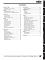
J8=<KP%%%%%%%%%%%%%%%%%%%%%%%%%%%%%%%%%%%%%%%%%%%%%%%.
Standard Machinery Safety ..................... 7
Additional Safety for Wide Belt Sanders ..... 9
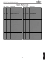
G8IKJ%%%%%%%%%%%%%%%%%%%%%%%%%%%%%%%%%%%%%%%%%%%%%% +.
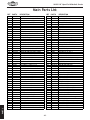
Main Breakdown ................................ 47
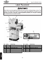
Label Placement ............................... 50
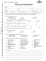
N8II8EKP%%%%%%%%%%%%%%%%%%%%%%%%%%%%%%%%%%%%%%%% ,+
FG<I8K@FEJ
D8@EK<E8E:<
FG<I8K@FEJ%%%%%%%%%%%%%%%%%%%%%%%%%%%%%%%%%%%%%%% (/
General .......................................... 18
Basic Controls ................................... 19
Choosing Sandpaper ........................... 20
Sanding Belt Replacement .................... 20
Conveyor Feed Rate ........................... 21
Depth of Cut .................................... 22
Amperage Load Meter ......................... 22
Sanding Belt Oscillation Rate ................ 23
Sanding Tips ..................................... 24
Sanding Operation ............................. 25
J<IM@:<%%%%%%%%%%%%%%%%%%%%%%%%%%%%%%%%%%%%%%%%%%%% )0
General .......................................... 29
Conveyor Belt Tensioning ..................... 29
Conveyor Belt Tracking ........................ 30
Gib Adjustment ................................. 31
Sanding Drum & Conveyor Parallelism ...... 32
Air Pressure Safety Switch .................... 34
Depth of Cut Safety Bar ....................... 35
Adjusting Pressure Rollers .................... 36
Replacing Conveyor Belt ...................... 37
Electrical Safety Instructions................. 39
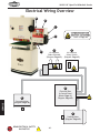
Electrical Wiring Overview ................... 40
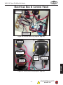
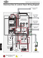
Electrical Box & Control Panel ............... 41
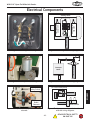
Electrical Components ........................ 43
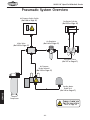
Pneumatic System Overview ................. 44
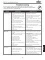
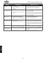
Troubleshooting................................. 45
J<KLG
J<KLG%%%%%%%%%%%%%%%%%%%%%%%%%%%%%%%%%%%%%%%%%%%%%% ((
Unpacking ....................................... 11
Inventory ........................................ 11
Machine Placement ............................ 12
Cleaning Machine............................... 12
Moving & Assembly ............................. 13
Compressed Air ................................. 15
Dust Collection ................................. 15
Test Run.......................................... 16
Recommended Adjustments .................. 17
D8@EK<E8E:<%%%%%%%%%%%%%%%%%%%%%%%%%%%%%%%%%%%% ).
General .......................................... 27
Cleaning ......................................... 27
Lubrication ...................................... 27
Air Regulator/Filter ............................ 28
<C<:KI@:8C
<C<:KI@:8C%%%%%%%%%%%%%%%%%%%%%%%%%%%%%%%%%%%%%%% ('
220V Operation ................................. 10
Extension Cords ................................ 10
Electrical Specifications ...................... 10
8::<JJFI@<J%%%%%%%%%%%%%%%%%%%%%%%%%%%%%%%%%%%%%% )Sander Accessories ............................. 26
J8=<KP
@EKIF;L:K@FE%%%%%%%%%%%%%%%%%%%%%%%%%%%%%%%%%%%%%)
Woodstock Technical Support .................. 2
Machine Overview ................................ 2
@EKIF;L:K@FE
:fek\ekj
J<IM@:<
G8IKJ
LJ<K?<HL@:B>L@;<G8><C89<CJKFJ<8I:?FLK@E=FID8K@FE=8JK
@EKIF;L:K@FE
N(/(*(/Fg\e<e[N`[\9\ckJXe[\i
@EKIF;L:K@FE
Nff[jkfZbK\Z_e`ZXcJlggfik
This machine has been specially designed to provide many years of trouble-free service. Close attention
to detail, ruggedly built parts and a rigid quality control program assure safe and reliable operation.
Woodstock International, Inc. is committed to customer satisfaction. Our intent with this manual is to
include the basic information for safety, setup, operation, maintenance, and service of this product.
We stand behind our machines! In the event that questions arise about your machine, please
contact Woodstock International Technical Support at (360) 734-3482 or send e-mail to:
[email protected]. Our knowledgeable staff will help you troubleshoot problems and process
warranty claims.
DXZ_`e\Fm\im`\n
An open end wide belt sander is designed to surface sand a workpiece that is twice the width of the
sander's capacity by rotating the workpiece 180° for the second and subsequent sanding passes.
The operator uses the elevation handwheel and scale to set the depth of cut, turns the sanding and conveyor motors FE, sets the feed rate or speed of the conveyor belt, then feeds the workpiece into the
sander at the same rate as the conveyor. Pressure rollers keep the workpiece held to the conveyor belt
to move it under the sanding drum. After each pass, the operator lowers the sanding belt the recommended amount and feeds the workpiece through the sander again.
The oscillation system shifts the sanding belt from side-to-side on the sanding drum to produce an even
sanding finish across the width of the workpiece. This system is operated with compressed air through a
series of air valves and levers. The sanding motor brake unit also requires compressed air, which brings
the sanding motor and sanding belt to a quick stop when the power is turned F==.
The depth of cut safety bar prevents a workpiece that is too high from being "jammed" into the sanding
belt, which could produce an unsafe hazard of kickback. As well, the air pressure safety switch will not
allow the machine to operate if the source of compressed air is below the operating minimum.
If you need the latest edition of this manual, you can download it from _kkg1&&nnn%j_fg]fo%Y`q.
If you have comments about this manual, please contact us at:
Nff[jkfZb@ek\ieXk`feXc#@eZ%
8kke1K\Z_e`ZXc;fZld\ekXk`feDXeX^\i
G%F%9fo)*'0
9\cc`e^_Xd#N80/)).
<dX`c1dXelXcj7nff[jkfZb`ek%Zfd
-2-
@EKIF;L:K@FE
N(/(*(/Fg\e<e[N`[\9\ckJXe[\i
=\Xkli\j
B
A
C
D
K
E
J
F
I
G
H
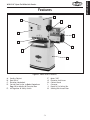
=`^li\(% Model W1813 features.
=%
>%
?%
@%
A%
B%
8%
9%
:%
;%
Sanding Cabinet
Dust Port 4"
Elevation Handwheel
Control Panel (refer to 9Xj`Z:fekifcj on
GX^\(0 for details) & Electrical Box
<% Air Regulator & Safety Switch
-3-
Motor 3 HP
Elevation Lock Lever
Cabinet Stand
Conveyor
Depth of Cut Safety Bar
Sanding Belt Access Door
@EKIF;L:K@FE
N(/(*(/Fg\e<e[N`[\9\ckJXe[\i
:fekifcj
A
I
H
B
J
C
K
G
N
D
M
E
L
F
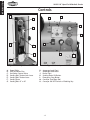
=`^li\)% Sanding cabinet controls.
8%
9%
:%
;%
<%
=%
>%
Upper Roller
Left Oscillation Disc
Oscillation Control Valve
Sanding Belt Tension Lock Lever
Sanding Belt Tension Lever
Sanding Drum
Sanding Belt 19" x 48"
=`^li\*% Control panel identification.
?%
@%
A%
B%
C%
D%
E%
Amperage Load Chart
Amperage Load Meter
Power Light
Sanding Motor ON Button
Emergency Stop Button
Conveyor Feed Rate Dial
Conveyor ON/OFF Switch w/Disabling Key
-4-
B68=>C:
HE:8>;>86I>DCH
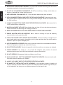
Phone #: (360) 734-3482 • Online Tech Support: [email protected] • Web: www.shopfox.biz
BD9:AL&-&(
&-DE:C":C9L>9:7:AIH6C9:G
Gif[lZk;`d\ej`fej1
Weight .................................................................................................................. 475 lbs.
Length/Width/Height .................................................................................. 42 1⁄2" x 24" x 621⁄2"
Foot Print (Length/Width)........................................................................................ 25" x 171⁄2"
J_`gg`e^;`d\ej`fej1
9fo(
Type .......................................................................................... Wood Pallet + Cardboard
Content ........................................................................................................... Machine
Weight............................................................................................................. 470 lbs.
Length/Width/Height ................................................................................... 47" x 26" x 39"
9fo)
Type ............................................................................................................ Cardboard
Content .............................................................................................................. Stand
Weight...............................................................................................................92 lbs.
Length/Width/Height ................................................................................... 19" x 27" x 26"
<c\Zki`ZXc1
Switch ............................................................................ Magnetic Switch with Thermal Overload
Switch Voltage ............................................................................................................. 220V
Cord Length.............................................................................................................. 61⁄2 ft.
Cord Gauge ............................................................................................................ 14 gauge
Recommended Circuit Size ................................................................................................ 20A
Plug .............................................................................................................................No
Dfkfij1
JXe[`e^;ild
Type ................................................................................... TEFC Capacitor Start Induction
Horsepower .......................................................................................................... 3 HP
Voltage ............................................................................................................. 220VAC
Phase ................................................................................................................ Single
Amps ................................................................................................................... 14A
Speed............................................................................................................ 1725 RPM
Cycle ................................................................................................................. 60 Hz
Number Of Speeds ...................................................................................................... 1
Power Transfer .............................................................................................. Direct Drive
Bearings ......................................................................................... Sealed and Lubricated
-5-
@EKIF;L:K@FE
N(/(*(/Fg\e<e[N`[\9\ckJXe[\i
@EKIF;L:K@FE
N(/(*(/Fg\e<e[N`[\9\ckJXe[\i
:fem\pfi=\\[
Type .................................................................................... Direct Current Variable Speed
Horsepower ........................................................................................................ 1⁄10 HP
Voltage .............................................................................................................220VDC
Phase ................................................................................................................ Single
Amps ..................................................................................................................... 1A
Number of Speeds ............................................................................................... Variable
Speed........................................................................................................... 10–34 RPM
Cycle ................................................................................................................. 60 Hz
Power Transfer ...................................................................................................Gearbox
Bearings ......................................................................................... Sealed and Lubricated
DX`eJg\Z`]`ZXk`fej
Fg\iXk`fe@e]fidXk`fe
Number of Sanding Drums ............................................................................................. 1
Maximum Board Width ............................................................................................... 18"
Minimum Board Width ................................................................................................. 2"
Maximum Board Thickness ............................................................................................ 6"
Minimum Board Thickness ........................................................................................... 1⁄4"
Minimum Board Length ................................................................................................ 6"
Sanding Drum Speed .......................................................................................... 1850 FPM
Sanding Drum Diameter ............................................................................................... 4"
Conveyor Feed Rate ...........................................................................................5–17 FPM
Sandpaper Length ..................................................................................................... 48"
Sandpaper Width ...................................................................................................... 19"
JXe[`e^;ild@e]fidXk`fe
Drum Type ......................................................................................................... Rubber
Drum Diameter ......................................................................................................... 4"
:fejkilZk`fe@e]fidXk`fe
Conveyor Belt ...................................................................................... Heavy-Duty Rubber
Body ...................................................................................................................Steel
Paint ......................................................................................................... Powder Coat
Table and Column .............................................................................................. Cast Iron
Cabinet Stand ........................................................................................................Steel
Fk_\i@e]fidXk`fe
Number of Pressure Rollers ............................................................................................ 2
Pressure Roller Type ................................................................................................Steel
Pressure Roller Diameter............................................................................................. 3⁄4"
Number of Dust Ports ................................................................................................... 1
Dust Port Size ........................................................................................................... 4"
Fk_\iJg\Z`]`ZXk`fej1
Country of Origin ....................................................................................................... Taiwan
Warranty .................................................................................................................. 2 Year
Serial Number Location ................................................................................... ID Label on Front
Assembly Time ...........................................................................................................1 Hour
Required Air Pressure ................................................................................................... 57 PSI
=\Xkli\j1
Variable Speed Conveyor Feed
Pneumatic Belt Tracking
Emergency Brake System
Spring Belt Tensioning System
Amp Load Meter
-6-
N(/(*(/Fg\e<e[N`[\9\ckJXe[\i
J8=<KP
J8=<KP
@e[`ZXk\jXe`dd`e\ekcp_XqXi[fljj`klXk`fen_`Z_#`]efkXmf`[\[#N@CC
i\jlck`e[\Xk_fij\i`flj`ealip%
@e[`ZXk\jXgfk\ek`Xccp_XqXi[fljj`klXk`fen_`Z_#`]efkXmf`[\[#:FLC;
i\jlck`e[\Xk_fij\i`flj`ealip%
@e[`ZXk\jXgfk\ek`Xccp_XqXi[fljj`klXk`fen_`Z_#`]efkXmf`[\[#D8P
i\jlck`ed`efifidf[\iXk\`ealip%
EFK@:<
K_`jjpdYfc`jlj\[kfXc\ikk_\lj\ikflj\]lc`e]fidXk`feXYflkgifg\i
fg\iXk`fef]k_\\hl`gd\ek#Xe[&fiXj`klXk`fek_XkdXpZXlj\[XdX^\
kfk_\dXZ_`e\ip%
JkXe[Xi[JX]\kp@ejkilZk`fej
JkXe[Xi[DXZ_`e\ipJX]\kp
(% I<8;K?IFL>?K?<<EK@I<D8EL8C9<=FI<JK8IK@E>D8:?@E<IP%DXZ_`e\ipgi\j\ekjj\i`flj
`ealip_XqXi[jkflekiX`e\[lj\ij%
)% 8CN8PJ LJ< 8EJ@ 8GGIFM<; J8=<KP >C8JJ<J N?<E FG<I8K@E> D8:?@E<IP% <m\ip[Xp \p\$
^cXjj\jfecp_Xm\`dgXZki\j`jkXekc\ej\jÇk_\pXi\EFKjX]\kp^cXjj\j%
*% 8CN8PJN<8I8E@FJ?8GGIFM<;I<JG@I8KFIN?<EFG<I8K@E>D8:?@E<IPK?8KGIF;L:<J
;LJK%Nff[[ljk`jXZXiZ`ef^\eXe[ZXeZXlj\ZXeZ\iXe[j\m\i\i\jg`iXkfip`cce\jj\j%
+% 8CN8PJ LJ< ?<8I@E> GIFK<:K@FE N?<E FG<I8K@E> D8:?@E<IP% DXZ_`e\ip ef`j\ ZXe ZXlj\
g\idXe\ek_\Xi`e^[XdX^\%
,% N<8IGIFG<I8GG8I<C%;FEFKn\Xicffj\Zcfk_`e^#^cfm\j#e\Zbk`\j#i`e^j#fia\n\cipn_`Z_dXp
^\k ZXl^_k `e dfm`e^ gXikj% N\Xi gifk\Zk`m\ _X`i Zfm\i`e^ kf ZfekX`e cfe^ _X`i Xe[ n\Xi efe$jc`g
]ffkn\Xi%
-% E<M<IFG<I8K<D8:?@E<IPN?<EK@I<;#FILE;<IK?<@E=CL<E:<F=;IL>JFI8C:F?FC%
9\d\ekXccpXc\ikXkXcck`d\jn_\eilee`e^dXZ_`e\ip%
.% FECP8CCFNKI8@E<;8E;GIFG<ICPJLG<IM@J<;G<IJFEE<CKFFG<I8K<D8:?@E<IP%DXb\
jli\fg\iXk`fe`ejkilZk`fejXi\jX]\Xe[Zc\Xicple[\ijkff[%
/% B<<G:?@C;I<E8E;M@J@KFIJ8N8P%B\\gXccZ_`c[i\eXe[m`j`kfijXjX]\[`jkXeZ\]ifdk_\nfib
Xi\X%
0% D8B<NFIBJ?FG:?@C;GIFF=%Lj\gX[cfZbj#dXjk\ijn`kZ_\j#Xe[i\dfm\jkXikjn`kZ_b\pj%
-7-
J8=<KP
I<8;D8EL8C9<=FI<FG<I8K@E>D8:?@E<%
=8@CLI<KF=FCCFN@EJKIL:K@FEJ9<CFNN@CC
I<JLCK@EG<IJFE8C@EALIP%
N(/(*(/Fg\e<e[N`[\9\ckJXe[\i
('% E<M<IC<8M<N?<ED8:?@E<@JILEE@E>%Kliegfn\iF==Xe[XccfnXccdfm`e^gXikjkfZfd\kf
XZfdgc\k\jkfgY\]fi\c\Xm`e^dXZ_`e\leXkk\e[\[%
J8=<KP
((% ;FEFKLJ<@E;8E><IFLJ<EM@IFED<EKJ%;FEFKlj\dXZ_`e\ip`e[Xdg#n\kcfZXk`fej#fi
n_\i\Xep]cXddXYc\fiefo`flj]ld\jdXp\o`jk%
()% B<<GNFIB8I<8:C<8E8E;N<CCC@K%:clkk\iXe[[Xibj_X[fnjdXpZXlj\XZZ`[\ekj%
(*% LJ<8>IFLE;<;<OK<EJ@FE:FI;I8K<;=FIK?<D8:?@E<8DG<I8><%Le[\ij`q\[Zfi[jfm\i$
_\XkXe[cfj\gfn\i%I\gcXZ\\ok\ej`feZfi[j`]k_\pY\Zfd\[XdX^\[%;FEFKlj\\ok\ej`feZfi[j
]fi))'MdXZ_`e\ip%
(+% 8CN8PJ;@J:FEE<:K=IFDGFN<IJFLI:<9<=FI<J<IM@:@E>D8:?@E<IP%DXb\jli\jn`kZ_`j
`eF==gfj`k`feY\]fi\i\Zfee\Zk`e^%
(,% D8@EK8@ED8:?@E<IPN@K?:8I<%B\\gYcX[\jj_XigXe[Zc\Xe]fiY\jkXe[jX]\jkg\i]fidXeZ\%
=fccfn`ejkilZk`fej]ficlYi`ZXk`e^Xe[Z_Xe^`e^XZZ\jjfi`\j%
(-% D8B<JLI<>L8I;J8I<@EGC8:<8E;NFIB:FII<:KCP9<=FI<LJ@E>D8:?@E<IP%
(.% I<DFM< 8;ALJK@E> B<PJ 8E; NI<E:?<J% DXb\ X _XY`k f] Z_\Zb`e^ ]fi b\pj Xe[ X[aljk`e^
ni\eZ_\jY\]fi\klie`e^dXZ_`e\ipFE%
(/% :?<:B =FI ;8D8><; G8IKJ 9<=FI< LJ@E> D8:?@E<IP% :_\Zb ]fi Y`e[`e^ Xe[ Xc`^ed\ek f]
gXikj#Yifb\egXikj#gXikdflek`e^#cffj\Yfckj#Xe[Xepfk_\iZfe[`k`fejk_XkdXpX]]\ZkdXZ_`e\
fg\iXk`fe%I\gX`ifii\gcXZ\[XdX^\[gXikj%
(0% LJ<I<:FDD<E;<;8::<JJFI@<J%I\]\ikfk_\`ejkilZk`fedXelXc]fii\Zfdd\e[\[XZZ\jjfi`\j%
K_\lj\f]`dgifg\iXZZ\jjfi`\jdXpZXlj\i`jbf]`ealip%
)'%;FEFK=FI:<D8:?@E<IP%NfibXkk_\jg\\[]fin_`Z_k_\dXZ_`e\fiXZZ\jjfipnXj[\j`^e\[%
)(% J<:LI< NFIBG@<:<% Lj\ ZcXdgj fi X m`j\ kf _fc[ k_\ nfibg`\Z\ n_\e giXZk`ZXc% 8 j\Zli\[
nfibg`\Z\gifk\Zkjpfli_Xe[jXe[]i\\jYfk__Xe[jkffg\iXk\k_\dXZ_`e\%
))% ;FEFKFM<II<8:?%B\\ggifg\i]ffk`e^Xe[YXcXeZ\XkXcck`d\j%
)*% D8EPD8:?@E<JN@CC<A<:KK?<NFIBG@<:<KFN8I;K?<FG<I8KFI%BefnXe[Xmf`[Zfe[`$
k`fejk_XkZXlj\k_\nfibg`\Z\kfb`ZbYXZb%
)+% 8CN8PJCF:BDF9@C<98J<J@=LJ<; 9<=FI<FG<I8K@E>D8:?@E<IP%
),% 9< 8N8I< K?8K :<IK8@E ;LJK D8P 9< ?8Q8I;FLJ kf k_\ i\jg`iXkfip jpjk\dj f] g\fgc\ Xe[
Xe`dXcj#\jg\Z`Xccp]`e\[ljk%DXb\jli\pflbefnk_\_XqXi[jXjjfZ`Xk\[n`k_k_\kpg\f][ljkpfl
n`ccY\\ogfj\[kfXe[XcnXpjn\XiXi\jg`iXkfiXggifm\[]fik_Xkkpg\f][ljk%
-8-
N(/(*(/Fg\e<e[N`[\9\ckJXe[\i
8[[`k`feXcJX]\kp]fiN`[\9\ckJXe[\ij
LJ<k_`jXe[fk_\idXZ_`e\ipn`k_ZXlk`fe
Xe[ i\jg\Zk% 8cnXpj Zfej`[\i jX]\kp ]`ijk#
Xj `k Xggc`\j kf pfli `e[`m`[lXc nfib`e^
Zfe[`k`fej%Efc`jkf]jX]\kp^l`[\c`e\jZXe
Y\ Zfdgc\k\Ç\m\ip j_fg \em`ifed\ek `j
[`]]\i\ek%=X`cli\kf]fccfn^l`[\c`e\jZflc[
i\jlck `e j\i`flj g\ijfeXc `ealip# [XdX^\
kf\hl`gd\ekfigffinfibi\jlckj%
(% B@:B98:B%Kickback is typically defined as the high-speed expulsion of stock from the machine,
which can cause serious personal injury to the operator or bystanders. Lek`cpfl_Xm\XZc\Xi
le[\ijkXe[`e^_fnb`ZbYXZbZXefZZlin_\elj`e^k_`jdXZ_`e\#;FEFKfg\iXk\k_`jjXe[\i
)% NFIBG@<:<=<<;I8K<% Forcing or jamming the workpiece into the sander or against the sanding
belt can cause it to kickback into the operator. Always use the correct depth of cut, then firmly
hold the workpiece and ease it into the sander at the same feed rate as the conveyor.
*% 8MF@;@E><EK8E>C<D<EK% Becoming entangled in the moving parts of this machine can cause
pinching and crushing injuries. To avoid these hazards, DO NOT wear loose clothing, gloves, or jewelry, and tie back long hair. Keep all guards in place and cabinet doors closed and secure.
+% ?8E;GC8:<D<EK% The sanding belt can remove a large amount of flesh in a few seconds.
Always keep hands away from the sanding belt. Avoid pinching injuries by never putting your hand
between the workpiece and the machine.
,% LE8KK<E;<;D8:?@E<% This machine represents serious hazards to an untrained operator. Always
turn the machine F== and remove the conveyor belt disabling key before leaving the machine.
-% NFIBG@<:<HL8EK@KP% Never sand two or more workpieces side-by-side. Since workpieces are
never exactly the same thickness, one of them may be thrown from the sander at a high rate of
speed and could cause serious personal injury.
.% NFIBG@<:<@EJG<:K@FE% Nails, staples, knots, or other imperfections in the workpiece can be dislodged and thrown from the sander at a high rate of speed into the operator or bystanders. Never
attempt to sand stock that has imperfections or embedded foreign objects.
/% 9F;PGC8:<D<EK% In case of kickback, avoid personal injury by always keeping your body to the
side of the sanding path.
0% GFN<I;@J:FEE<:K% Accidental start up or contact with live wiring could result in serious personal injury or death. Always disconnect the sander from power when changing the sanding belt,
making adjustments, performing maintenance, or servicing the machine.
-9-
J8=<KP
I<8;Xe[le[\ijkXe[k_`j
\ek`i\ `ejkilZk`fe dXelXc
Y\]fi\lj`e^k_`jdXZ_`e\%
J\i`flj g\ijfeXc `ealip
dXp fZZli `] jX]\kp Xe[
fg\iXk`feXc`e]fidXk`fe`j
efk le[\ijkff[ Xe[ ]fc$
cfn\[% ;F EFK i`jb pfli
jX]\kpYpefki\X[`e^
N(/(*(/Fg\e<e[N`[\9\ckJXe[\i
<C<:KI@:8C
<C<:KI@:8C
K_\ dXZ_`e\ dljk Y\ gifg\icp j\k lg Y\]fi\ `k `j
jX]\kffg\iXk\%;FEFKZfee\Zkk_`jdXZ_`e\kfk_\
gfn\i jfliZ\ lek`c `ejkilZk\[ kf [f jf `e k_\ K\jk
Ilegfik`fef]k_`jdXelXc%
))'MFg\iXk`fe
-$)'G
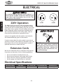
The Model W1813 is wired for 220V single-phase operation. We recommend connecting this machine to a dedicated circuit with a verified ground, using the circuit size
given below. Never replace a circuit breaker with one of
higher amperage without consulting a qualified electrician to ensure compliance with wiring codes. This machine must be connected to a grounded circuit!
-$)'I
=`^li\+% NEMA 6-20 plug and receptacle.
A plug is not supplied with this machine. See below for
the recommended plug type for this machine.
If you are unsure about the wiring codes in your area or
you plan to connect your machine to a shared circuit, you
may create a fire or circuit overload hazard—consult a
qualified electrician to reduce this risk.
<ok\ej`fe:fi[j
We do not recommend using an extension cord; however,
if you have no alternative, use the following guidelines:
•
•
•
•
;FEFKnfibfepfli\c\Zki`ZXcjpjk\d
`] pfl Xi\ lejli\ XYflk \c\Zki`ZXc
Zf[\jXe[n`i`e^J\\bXjj`jkXeZ\]ifd
X hlXc`]`\[ \c\Zki`Z`Xe% @^efi`e^ k_`j
nXie`e^ZXeZXlj\\c\ZkifZlk`fe#]`i\#
fidXZ_`e\[XdX^\%
Use a cord rated for Standard Service (S).
Do not use an extension cord longer than 50 feet.
Ensure that the cord has a ground wire and pin.
Use the gauge size listed below as a minimum.
<c\Zki`ZXcJg\Z`]`ZXk`fej
Fg\iXk`e^MfckX^\
8dg;iXn
D`e%:`iZl`kJ`q\
I\Zfdd\e[\[Gcl^
<ok\ej`fe:fi[
220V Operation
15 Amps
20A
NEMA 6-20 (not incl.)
12 Gauge
-10-
N(/(*(/Fg\e<e[N`[\9\ckJXe[\i
J<KLG
LegXZb`e^
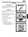
This machine has been carefully packaged for safe transportation. If you notice the machine has been damaged
during shipping, please contact your authorized Shop Fox
dealer immediately.
@em\ekfip
The following is a description of the main components
shipped with the Model W1813. Lay the components out
to inventory them.
B\\g dXZ_`e\ [`jZfee\Zk\[ ]ifd
gfn\ilek`c`ejkilZk\[fk_\in`j\%
Efk\1 @]pflZXek]`e[Xe`k\dfek_`jc`jk#Z_\Zbk_\
dflek`e^cfZXk`fefek_\dXZ_`e\fi\oXd`e\k_\gXZb$
X^`e^dXk\i`XcjZXi\]lccp%FZZXj`feXccpn\gi\$`ejkXccZ\i$
kX`eZfdgfe\ekj]fijX]\ij_`gg`e^%
J<KLG
9fo(@em\ekfip=`^li\, Hkp
8% Sander Assembly ...........................................1
9% Sanding Belt 19" x 48" (Pre-Installed) ..................1
:% Conveyor Front Guard (Pre-Installed) ..................1
A
B
9fo)@em\ekfip=`^li\- Hkp
;% Cabinet Stand ..............................................1
?Xi[nXi\efkj_fne Hkp
— Machine Mounting Feet 3⁄8"-16 x 2" .................4
— Hex Nuts 3⁄8"-16 (Mounting Feet)....................4
— Flat Washers 3⁄8" (Mounting Feet) ...................8
— Hex Bolts M8-1.25 x 25 (Assembly-to-Stand) .......4
— Flat Washers 8mm (Assembly-to-Stand) .............4
C
=`^li\,% Model W1813 box 1 inventory.
D
=`^li\-% Model W1813 box 2 inventory.
-11-
N(/(*(/Fg\e<e[N`[\9\ckJXe[\i
J<KLG
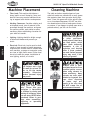
DXZ_`e\GcXZ\d\ek
=cffiCfX[1 This machine distributes a
heavy load in a small footprint. Some residential floors may require additional bracing to support both machine and operator.
Nfib`e^:c\XiXeZ\j1 Consider existing and
anticipated needs, size of material to be
processed through the machine, and space
for auxiliary stands, work tables or other
machinery when establishing a location for
your wide belt sander.
C`^_k`e^1 Lighting should be bright enough
to eliminate shadow and prevent eye
strain.
<c\Zki`ZXc1Electrical circuits must be dedicated or large enough to handle amperage
requirements. Outlets must be located near
each machine, so power or extension cords
are clear of high-traffic areas. Follow local
electrical codes for proper installation of
new lighting, outlets, or circuits.
:c\Xe`e^DXZ_`e\
The table and other unpainted parts of your
wide belt sander are coated with a waxy grease
that protects them from corrosion during shipment. Clean this grease off with a solvent cleaner or citrus-based degreaser. DO NOT use chlorine-based solvents such as brake parts cleaner
or acetone—if you happen to splash some onto a
painted surface, you will ruin the finish.
E<M<IZc\Xen`k_^Xjfc`e\
fi fk_\i g\kifc\ld$
YXj\[jfcm\ekj%Dfjk_Xm\
cfn ]cXj_ gf`ekj# n_`Z_
dXb\ k_\d \oki\d\cp
]cXddXYc\% 8 i`jb f]
\ogcfj`fe Xe[ Ylie`e^
\o`jkj `] k_\j\ gif[lZkj
Xi\lj\[%J\i`fljg\ijfeXc
`ealip dXp fZZli `] k_`j
nXie`e^`j`^efi\[
8CN8PJ nfib `e n\cc$
m\ek`cXk\[Xi\Xj]Xi]ifd
gfjj`Yc\ `^e`k`fe jfliZ\j
n_\e lj`e^ jfcm\ekj kf
Zc\Xe dXZ_`e\ip% DXep
jfcm\ekj Xi\ kfo`Z n_\e
`e_Xc\[ fi `e^\jk\[% Lj\
ZXi\ n_\e [`jgfj`e^
f] nXjk\ iX^j Xe[
kfn\cj kf Y\ jli\ k_\p
;F EFK Zi\Xk\ ]`i\ fi
\em`ifed\ekXc_XqXi[j%
LJ< _\cg\ij Xe[ X ]fib
c`]kiXk\[]fiXkc\Xjk.,'
cYj% kf c`]k k_\ jXe[\i
Xjj\dYcp% Fk_\in`j\#
j\i`flj g\ijfeXc `ealip
dXpfZZli%
D8B< pfli j_fg ÈZ_`c[
jX]\%É <ejli\ k_Xk pfli
nfibgcXZ\ `j `eXZZ\jj`Yc\
kf Z_`c[i\e Yp Zcfj`e^ Xe[
cfZb`e^Xcc\ekiXeZ\jn_\e
pflXi\XnXp%E<M<IXccfn
lekiX`e\[ m`j`kfij `e pfli
j_fg n_\e Xjj\dYc`e^#
X[aljk`e^ fi fg\iXk`e^
\hl`gd\ek%
-12-
N(/(*(/Fg\e<e[N`[\9\ckJXe[\i
Dfm`e^8jj\dYcp
KffcjE\\[\[
Hkp
1
Wrench ⁄2"....................................................... 1
Wrench 9⁄16" ...................................................... 1
Precision Level .................................................. 1
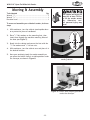
Kfdfm\Xe[Xjj\dYc\pflin`[\Y\ckjXe[\i#[fk_\j\
jk\gj1
With assistance, turn the cabinet stand upside down
on a protective piece of cardboard.
)%
Place 3⁄8" flat washers on the mounting feet, then
insert them through the machine mounting holes of
the base (see =`^li\.).
*%
Reach into the cabinet and secure the feet with the
3
⁄8" flat washers and 3⁄8"-16 hex nuts.
+%
With assistance, turn the cabinet over and place it in
the desired location.
,%
Have your assistant steady the sander assembly as
you place the forklift forks in a stable position under
the conveyor, as shown in =`^li\/%
J<KLG
(%
LJ<_\cg\ijXe[X]fibc`]k
iXk\[]fiXkc\Xjk.,'cYj%
kf c`]k k_\ jXe[\i Xjj\d$
Ycp% Fk_\in`j\# j\i`$
flj g\ijfeXc `ealip dXp
fZZli%
=`^li\.%Mounting foot installed onto
sanding cabinet.
=`^li\/% Forklift forks properly positioned
under the conveyor.
-13-
N(/(*(/Fg\e<e[N`[\9\ckJXe[\i
-%
Lift and move the sander assembly into position over
the cabinet stand so that the mounting holes line up
(see =`^li\j0Æ(').
.%
Secure the sander assembly to the cabinet stand
with the four M8-1.25 x 25 hex bolts and 8mm flat
washers.
/%
Open the sanding belt access door on the left side
of the machine, and remove the red shipping brace
securing the sanding drum to the conveyor assembly
(see =`^li\(().
J<KLG
Only use a forklift rated for at least 750 lbs. that is in
good working condition. Use assistants to steady the
load when lifting and moving the sander assembly. If
the sander assembly should tip or fall, serious personal injury and property damage could result.
=`^li\0% Sander assembly mounting points
on left side.
=`^li\('% Sander assembly mounting
points on right side.
Shipping Brace
=`^li\((% Shipping brace.
-14-
N(/(*(/Fg\e<e[N`[\9\ckJXe[\i
:fdgi\jj\[8`i
A steady supply of clean, dry air of 57–60 PSI (not to
exceed 120 PSI) is required for the operation of the
sanding belt oscillation system and pneumatic motor
brake. Without the correct supply of compressed air, the
machine will not start.
KfZfee\ZkXe[Zfe]`^li\Zfdgi\jj\[X`i]fik_\jXe[$
\i#[fk_\j\jk\gj1
(%
)%
Connect the source of compressed air to the air
regulator inlet valve on the back of the machine (see
=`^li\()).
To avoid possible personal injury from
exploding compressed air components
or damage to the sander, never exceed
120 PSI of incoming compressed air to
the mill's regulator.
Air Inlet
Valve
Lift up on the air regulator adjusting knob and turn
it so that the air pressure dial reads 57–60 PSI, then
push the adjusting knob down to lock the setting.
Recommended CFM at Dust Port: ...................400 CFM
Do not confuse this CFM recommendation with the rating
of the dust collector. To determine the CFM at the dust
port, you must take into account many variables, including the CFM rating of the dust collector, the length of
hose between the dust collector and the machine, the
amount of branches or Y's, and the amount of other open
lines throughout the system. Explaining this calculation
is beyond the scope of this manual. If you are unsure of
your system, consult an expert or purchase a good dust
collection "how-to" book.
Air Pressure
Dial
=`^li\()% Air regulator assembly on the
back of the sander.
KfZfee\Zkk_\[ljkZfcc\Zk`fe_fj\#[fk_\j\jk\gj1
(%
Fit a 4" dust hose over the dust port on top of the
machine, as shown in =`^li\(*, and secure it in
place with a hose clamp.
)%
Tug the hose to make sure it does not come off. A
tight fit is necessary for proper performance.
;F EFK fg\iXk\ k_`j dXZ_`e\ n`k_flk Xe X[\hlXk\
[ljkZfcc\Zk`fejpjk\d%K_`jdXZ_`e\Zi\Xk\jjlYjkXe$
k`XcXdflekjf]nff[[ljkn_`c\fg\iXk`e^%=X`cli\kf
lj\ X [ljk Zfcc\Zk`fe jpjk\d ZXe i\jlck `e j_fik Xe[
cfe^$k\idi\jg`iXkfip`cce\jj%
-15-
=`^li\(*% Dust hose connected to dust
port.
J<KLG
;ljk:fcc\Zk`fe
Adjusting
Knob
N(/(*(/Fg\e<e[N`[\9\ckJXe[\i
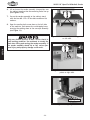
K\jkIle
Once the assembly is complete, test run your machine to
make sure it runs properly and is ready for regular operation.
KN@JK
The test run consists of verifying the following: 1) The
motors power up and run correctly, 2) the emergency stop
button safety feature works correctly, 3) the conveyor ON/
OFF switch disabling key works correctly, and 4) the air
pressure safety switch operates properly.
If, during the test run, you cannot easily locate the source
of an unusual noise or vibration, stop using the machine
immediately, then review KiflYc\j_ffk`e^ on GX^\+,.
If you still cannot remedy a problem, contact our Tech
Support at (360) 734-3482 for assistance.
J<KLG
Kfk\jkilek_\dXZ_`e\#]fccfnk_\j\jk\gj1
(%
Ensure all tools and objects used during
setup are cleared away from the machine.
*%
Connect the compressed air source to the
machine (refer to :fdgi\jj\[8`ion GX^\
(, for detailed instructions).
+%
Confirm the sanding belt is installed,
properly tensioned (refer to JXe[`e^9\ck
I\gcXZ\d\ek on GX^\)' for detailed
instructions), and the sanding belt door is
closed and secured.
,%
-%
Kn`jk9lkkfe:cfZbn`j\
=`^li\(+% Resetting the switch.
.%
Make sure you understand the safety
instructions at the beginning of the manual,
and verify that the machine is set up properly.
)%
KfI\j\kJn`kZ_%%%
Push the sanding motor ON button to verify
the machine starts and operates correctly.
—When operating correctly, the machine
runs smoothly with little or no vibration
or rubbing noises.
— Investigate and correct strange or unusual noises or vibrations before operating
the machine further. Always stop the
machine and disconnect it from power
before investigating or correcting potential problems.
Connect the machine to the power source—
the power light on the control panel should
light.
/%
Press the emergency stop button to turn
the machine F==.
0%
WITHOUT resetting the switch, press the
sanding motor ON button. The machine
should not start.
— If the machine does not start, the emergency stop button safety feature is working correctly.
Push the emergency stop button in, then
twist it clockwise so it pops out. When
the emergency stop button pops out, the
switch is reset and ready for operation (see
=`^li\(+).
— If the machine does start (with the emergency stop button pushed in), immediately disconnect power to the machine.
The emergency stop button safety feature is not working correctly. This safety
feature must work properly before proceeding with regular operations. Call
Tech Support for help.
Efk\1;li`e^k_\e\okjk\g#pfln`cc_\Xi
Xd\kXcc`Zk_ldgn_\ek_\jXe[`e^Y\ck
Z_Xe^\jfjZ`ccXk`fe[`i\Zk`feÇk_`jef`j\`j
efidXc%
-16-
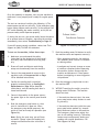
N(/(*(/Fg\e<e[N`[\9\ckJXe[\i
('% Reset the emergency stop button, then turn the
sanding motor FE.
Efk\1K_\jXe[`e^dfkfidljkY\FE Y\]fi\k_\
Zfem\pfiZXeY\jkXik\[%
((% Turn the conveyor FE and verify that it operates
correctly—it should move from front-to-back. Use
the conveyor feed rate dial to vary the speed.
()% Turn the conveyor F==, then remove the switch disabling key, as shown in =`^li\(,.
(*% Try to turn the conveyor FE.
— If the conveyor does not start, the switch disabling
feature is working as designed.
(+% Press the emergency stop button to turn the sanding
motor F==, re-install the switch disabling key, then
reset the emergency stop button.
(,% Disconnect the compressed air source from the sander and attempt to turn the sanding motor FE.
— If the machine does not start, the air pressure
safety switch is working correctly.
— If the machine does start (with the compressed air
source disconnected from the machine), immediately turn the machine F== and disconnect it from
power. The air pressure safety switch is not working correctly. This safety feature must work properly before proceeding with regular operations.
Call Tech Support for help.
(-% When all of the steps of the K\jkIleprocedure
have been successfully completed, your sander is
ready for operation.
-17-
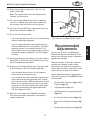
I\Zfdd\e[\[
8[aljkd\ekj
For your convenience, the adjustments
listed below have been performed at the
factory and no further setup is required to
operate your machine.
However, because of the many variables
involved with shipping, some of these
adjustments may need to be repeated to
ensure optimum results. Keep this in mind
as you start to use your new machine.
Step-by-step instructions for these adjustments can be found in the J<IM@:<section
of this manual.
•
Conveyor Belt Tensioning (GX^\)0) &
Tracking (GX^\*').
•
Gib Adjustment (GX^\*().
•
Sanding Drum & Conveyor Parallelism
(GX^\*)).
•
Air Pressure Safety Switch (GX^\*+).
•
Depth of Cut Safety Bar Height (GX^\
*,).
•
Pressure Roller Adjustment (GX^\*-).
J<KLG
— If the conveyor does start, immediately stop the
machine and disconnect it from power. The switch
disabling feature is not working correctly. This
safety feature must work properly before proceeding with the regular operations. Call Tech Support
for help.
=`^li\(,% Removing the switch disabling
key from the conveyor ON/OFF switch.
N(/(*(/Fg\e<e[N`[\9\ckJXe[\i
FG<I8K@FEJ
>\e\iXc
This machine will perform many types of operations
that are beyond the scope of this manual. Many of these
operations can be dangerous or deadly if performed incorrectly.
The instructions in this section are written with the
understanding that the operator has the necessary knowledge and skills to operate this machine. @]XkXepk`d\
pflXi\\og\i`\eZ`e^[`]]`Zlck`\jg\i]fid`e^Xepfg\iX$
k`fe#jkfglj`e^k_\dXZ_`e\
FG<I8K@FEJ
If you are an inexperienced operator, we strongly recommend that you read books, trade articles, or seek training
from an experienced n`[\Y\ckjXe[\i operator before
performing any unfamiliar operations. 8Yfm\Xcc#pfli
jX]\kpj_flc[Zfd\]`ijk
I<8;Xe[le[\ijkXe[k_`j\ek`i\`ejkilZ$
k`fe dXelXc Y\]fi\ lj`e^ k_`j dXZ_`e\%
J\i`flj g\ijfeXc `ealip dXp fZZli `]
jX]\kpXe[fg\iXk`feXc`e]fidXk`fe`jefk
le[\ijkff[ Xe[ ]fccfn\[% ;F EFK i`jb
pflijX]\kpYpefki\X[`e^
;FEFK`em\jk`^Xk\gifYc\djfiX[aljk
k_\ dXZ_`e\ n_`c\ `k `j ilee`e^% NX`k
lek`c k_\ dXZ_`e\ `j klie\[ F==#
legcl^^\[ Xe[ Xcc nfib`e^ gXikj
_Xm\Zfd\kfXZfdgc\k\jkfgY\]fi\
gifZ\\[`e^
8cnXpj n\Xi jX]\kp ^cXjj\j Xe[ X i\j$
g`iXkfi n_\e fg\iXk`e^ k_`j dXZ_`e\%
=X`cli\kfZfdgcpdXpi\jlck`ej\i`flj
g\ijfeXc`ealip%
-18-
N(/(*(/Fg\e<e[N`[\9\ckJXe[\i
9Xj`Z:fekifcj
Refer to =`^li\(- and the following descriptions to become familiar with the basic controls of your
sander.
B
A
C
J
D
I
G
F
E
=`^li\(-% Basic controls.
8% 8dg\iX^\CfX[:_Xik1Displays the amperage range for safe operation of the sanding
motor. NEVER operate the sander above the
SAFE range!
=% :fem\pfi=\\[IXk\;`Xc1Controls the
feed rate of the conveyor between 5 and
17 feet per minute (FPM).
>% :fem\pfiFE&F==Jn`kZ_n&;`jXYc`e^B\p1
Starts or stops the conveyor motor. Remove
the key to disable the switch.
9% 8dg\iX^\CfX[D\k\i1Shows the amperage used by the sanding motor during operation.
?% <c\mXk`feCfZb1Locks the sander assembly
in place above the conveyor after repositioning it with the elevation handwheel.
:% Gfn\iC`^_k1Lights when power is connected to the machine.
;% JXe[`e^DfkfiFE9lkkfe1Starts the sanding motor when pressed.
@%
<% <d\i^\eZpJkfg9lkkfe1Turns the sanding
and conveyor motors F==. This button does
NOT disconnect the machine from power.
<c\mXk`feJZXc\Gf`ek\i1Displays the
height of the sanding drum above the conveyor.
A% <c\mXk`fe?Xe[n_\\c1Raises and lowers
the sander assembly above the conveyor.
-19-
FG<I8K@FEJ
H
N(/(*(/Fg\e<e[N`[\9\ckJXe[\i
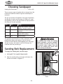
:_ffj`e^JXe[gXg\i
Sanding Belt Dimensions ..........................19"W x 48"L
There are many types of sanding belts to choose from. We
recommend aluminum oxide for general workshop environments.
FG<I8K@FEJ
The grit you choose will depend on the type of operation,
the species of wood, and the stage of finishing. As a general guideline, refer to the chart below to help you select
the right grit for your operation.
>i`k
36
:cXjj
Extra Coarse
60
Coarse
80-100
Medium
120-180
Fine
LjX^\
Rough sawn boards, thickness
sanding, and glue removal.
Thickness sanding and glue
removal.
Removing planer marks and
initial finish sanding.
Finish sanding.
The general rule of thumb is to sand a workpiece with
progressively higher grit numbers, with no one grit
increase of more than 50. Avoid skipping grits—the larger
the grit increase, the harder it will be to remove the
scratches from the previous grit.
JXe[`e^9\ckI\gcXZ\d\ek
The moving parts inside the sanding
cabinet represent a serious entanglement hazard. To avoid the risk of serious personal injury, always close and
secure the sanding belt access door
before starting the machine.
KfZ_Xe^\k_\jXe[`e^Y\ck#[fk_\j\jk\gj1
(%
DISCONNECT THE SANDER FROM POWER!
)%
Open the sanding belt access door and loosen the
tension lock shown in =`^li\(..
Tension Lock
Tension Lever
=`^li\(.% Sanding belt tension lock and
lever.
-20-
N(/(*(/Fg\e<e[N`[\9\ckJXe[\i
*%
To release the tension on the sanding belt, move
the tension lever up and to the right out of the top
catch, then use moderate force to push it down and
under the bottom catch, as shown in =`^li\(/.
Top
Catch
+%
Pull the sanding belt off the upper roller and the
sanding drum.
Bottom
Catch
,%
Slide the new sanding belt onto the upper roller and
sanding drum, then position it on the upper roller so
that it is just past the left oscillation disc, as shown
in =`^li\(0.
Efk\1DfjkjXe[`e^Y\ckj_Xm\Xiifnjgi`ek\[fe
k_\`i`ej`[\jli]XZ\kf`e[`ZXk\k_\[`i\Zk`fef]kiXm$
\c]fik_\Y\ck%DXkZ_k_\j\Xiifnjn`k_k_\jXe[`e^
Y\ck[`i\Zk`feXiifnj_fne`e=`^li\(/%
-%
When you have the sanding belt evenly positioned
between the oscillation discs on each end of the
upper roller, move the tension lever to the upper
catch by reversing from Jk\g*.
Sanding Belt
Direction
=`^li\(/% Tension lever secured under the
bottom catch.
Left
Oscillation
Disc
Efk\1K_\Df[\cN(/(*lj\jXjgi`e^k\ej`fe\ikf
XlkfdXk`ZXccpXggcpk_\Zfii\Zkk\ej`fekfk_\jXe[$
`e^Y\ckn_\ek_\k\ej`fec\m\i`jj\Zli\[fek_\
kfgZXkZ_%
Re-tighten the tension lock, then close and secure
the sanding belt access door before starting the
sander.
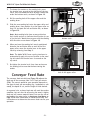
:fem\pfi=\\[IXk\
Sanding Belt
=`^li\(0% Proper position of the sanding
belt on the upper roller.
The conveyor feed rate dial (see =`^li\)') adjusts the
feed rate of the conveyor from 5 to 17 feet per minute
(FPM). The correct speed for your operation depends on
the type of stock you are sanding (e.g., hardwood vs. softwood), the depth of cut, and the stage of finish desired.
As a general rule, a slower feed rate will sand the surface
smoother, but runs the risk of burning the wood. A higher
feed rate will remove material faster, but runs the risk of
overloading the motor (refer to 8dg\iX^\CfX[D\k\ion
GX^\)) for more information on sander work load). Use
trial-and-error to determine the correct feed rate for your
operation.
=`^li\)'% Conveyor feed rate dial.
-21-
FG<I8K@FEJ
.%
N(/(*(/Fg\e<e[N`[\9\ckJXe[\i
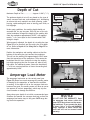
;\gk_f]:lk
Maximum Depth of Cut ............... Approx. 0.016" (1⁄64")
The optimum depth of cut will vary based on the type of
wood, conveyor feed rate, and sandpaper grit. Attempting
to remove too much material can cause jamming, wood
burning, rapid sanding belt wear or tearing, poor finish, or
belt slippage.
Elevation
Handwheel
Safety Bar
Under most conditions, the sanding depth should not
exceed 0.016" for any one pass. Each full turn of the elevation handwheel changes the height of the sanding belt
from the workpiece approximately 0.025", with approximately 2⁄3 of a turn equal to the recommended 0.016"
change in depth.
FG<I8K@FEJ
When properly adjusted, the depth of cut safety bar (see
=`^li\)() is an excellent tool for setting the ]`ijkdepth
of cut. Refer to ;\gk_f]:lkJX]\kp9Xi on GX^\*, for
more information.
Position the workpiece and sanding cabinet so that the
bottom of the safety bar just touches the workpiece.
This will set the sanding belt approximately 0.016" lower
than the top surface of the workpiece. Then rotate the
handwheel one full turn clockwise to raise the sanding
belt high enough so that the first pass will take off any
high spots. For additional passes, rotate the handwheel
2
⁄3 of a turn counterclockwise to lower the sanding belt
approximately 0.016".
Elevation
Scale
=`^li\)(% Depth of cut safety bar.
Amperage Load Chart
8dg\iX^\CfX[D\k\i
The amperage load meter on the control panel (see
=`^li\))) shows how much amperage the sanding motor
is drawing for the operation, or how hard the machine
is working. If the depth of cut or the conveyor feed rate
becomes too great, the sanding motor will draw an excessive amount of current (amperage), which may trip the
circuit breaker or damage the machine.
Always keep your depth of cut within recommended specifications and monitor the conveyor feed rate so that the
amperage load meter stays in the green SAFE range during the entire operation.
-22-
Amperage Load Meter
=`^li\))% Amperage load chart and
meter.
NOTICE
;F EFK MF@; K?< N8II8EKP B\\g
k_\ Xdg\iX^\ cfX[ d\k\i n`k_`e k_\
^i\\eJ8=<iXe^\j_fnefek_\Xdg\i$
X^\cfX[Z_Xik%@]pflfg\iXk\k_\jXe[$
\i XYfm\ (+8 fi `e k_\ i\[ N8IE@E>
iXe^\# ZXgXZ`kfi fi dfkfi ]X`cli\ dXp
fZZli Xe[ n`cc efk Y\ Zfm\i\[ le[\i
nXiiXekp%
N(/(*(/Fg\e<e[N`[\9\ckJXe[\i
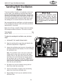
JXe[`e^9\ckFjZ`ccXk`fe
IXk\
To prevent sanding "streaks" in the workpiece and ensure
an even finish, the sanding belt oscillates from side-toside on the sanding drum during operation. This action is
caused by the twisting motion of the upper sanding roller
that causes the sanding belt to shift along the roller until
it hits the oscillation disc at the end, which then causes
the sanding belt to reverse direction to the other end.
We recommend that one oscillation cycle (the movement
of the sanding belt from one side to the other) should be
approximately 4–6 seconds.
NOTICE
K_\ jXe[`e^ Y\ck fjZ`ccXk`fe jpjk\d
i\hl`i\j X jfliZ\ f] Zc\Xe# [ip Zfd$
gi\jj\[ X`i Zfee\Zk kf k_\ dXZ_`e\
Xe[X[aljk\[kf,.Æ-'GJ@%N`k_flkk_`j
iXk\f]Zfdgi\jj\[X`i#k_\jXe[\in`cc
efkfg\iXk\%
Efk\1Pfln`cc_\XiXd\kXcc`Zk_ldgn_\ek_\jXe[`e^
Y\ckZ_Xe^\jfjZ`ccXk`fe[`i\Zk`fe%K_`jef`j\`jefidXc%
KffcjE\\[\[
Hkp
Wrench 12mm ................................................... 1
KfX[aljkk_\jXe[`e^Y\ckfjZ`ccXk`feiXk\#[fk_\j\
jk\gj1
(%
DISCONNECT THE SANDER FROM POWER!
Jam Nut
)%
*%
Open the sanding belt access door and identify the
oscillation stops shown in =`^li\)*.
FG<I8K@FEJ
Stops
Jam Nut
Loosen the oscillation stop jam nuts, then adjust the
oscillation stop hex bolts equally in or out to change
the oscillation rate.
Efk\1K_\fjZ`ccXk`feiXk\`jk_\k`d\`kkXb\jk_\
jXe[`e^Y\ckkfdfm\]ifdfe\j`[\f]k_\lgg\i
jXe[`e^ifcc\ikfk_\fk_\ij`[\Xe[_`kk_\fjZ`ccX$
k`fe[`jZXkk_\\e[%<XZ__\oYfckj\kk`e^X]]\Zkj
k_\fjZ`ccXk`feiXk\`efe\[`i\Zk`fe%K`^_k\e`e^X
jkfg_\oYfckn`ccZXlj\Xjcfn\ifjZ`ccXk`feiXk\]fi
k_Xk[`i\Zk`fe%<og\i`d\ekkf]`e[k_\i`^_kfjZ`ccX$
k`feiXk\]fipflifg\iXk`fe%
+%
Re-tighten the jam nuts without turning the hex
bolts, then close the access door.
,%
Connect the machine to power, start the sanding
motor, then check the oscillation rate.
-% Repeat Jk\gj(Æ, until you are satisfied with the
oscillation rate.
-23-
Hex Bolt
Hex Bolt
=`^li\)*% Sanding belt oscillation stops.
N(/(*(/Fg\e<e[N`[\9\ckJXe[\i
JXe[`e^K`gj
FG<I8K@FEJ
Follow these instructions to ensure safe sanding operation
and quality results:
•
Replace the sandpaper with a higher grit to achieve
a finer finish (refer to :_ffj`e^JXe[gXg\i on GX^\
)').
•
When making multiple passes on the workpiece,
avoid lowering the sanding belt more than 0.016"
(1⁄64" or 2⁄3 of a turn of the handwheel) for any one
pass.
•
Feed boards into the sander at different points on
the conveyor to maximize sandpaper life and prevent uneven conveyor belt wear.
•
DO NOT sand boards less than 6" long, 2" wide, or
1
⁄4" thick to avoid possible kickback, or damage to
the workpiece or sander.
•
Extend the life of the sanding belt by regularly using
a PRO-STICK© sanding pad (refer to 8::<JJFI@<J on
GX^\)-).
•
When sanding a workpiece with irregular widths,
take very light sanding passes to prevent gouges. As
the width of the workpiece decreases, the load on
the sanding motor will reduce and the sanding drum
will speed up, causing a gouge.
•
DO NOT edge sand boards. This can cause boards to
kickback, and may result in serious personal injury.
Edge sanding boards also can cause damage to the
conveyor belt and sandpaper.
•
Feed the workpiece into the sander at a slight angle
to maximize stock removal and sandpaper effectiveness, but feed the workpiece straight to reduce
sandpaper grit scratch for the finish passes.
•
When sanding workpieces with a bow or crown,
place the high point up, which prevents the
workpiece from rocking, and take very light passes.
-24-
Starting the sanding motor with a
workpiece in contact with the sanding belt could cause the workpiece to
kickback into the operator resulting in
serious personal injury. Never start the
sander with a workpiece or any object
on the conveyor belt.
N(/(*(/Fg\e<e[N`[\9\ckJXe[\i
JXe[`e^Fg\iXk`fe
Kfg\i]fidXkpg`ZXcjXe[`e^fg\iXk`fe#]fccfnk_\j\
jk\gj1
(%
Read and follow the safety instructions at the beginning of the manual, and make sure the machine is
set up properly before starting the sander.
)%
Connect the source of compressed air to the sander
and adjust the air regulator to 57–60 PSI.
*%
Make sure the workpiece is clean and free of any
defects or foreign materials that might cause kickback or damage to the sander.
+%
Start the dust collection system.
,%
Use the elevation handwheel to set the correct sanding depth of cut for the first pass (refer to ;\gk_f]
:lk on GX^\)) for detailed instructions).
DO NOT sand more than one board at
a time side-by-side. Minor variations
in workpiece thickness can cause one
board to be propelled into the operator
at a high rate of speed by the sanding
belt and could result in serious personal
injury.
Efk\1>\e\iXccp#k_\]`ijkgXjji\dfm\jk_\_`^_
jgfkj%
Turn the sanding motor FE.
.%
Turn the conveyor FE and correctly adjust the
conveyor feed rate for your operation (refer to
:fem\pfi=\\[IXk\on GX^\)( for detailed
instructions).
/%
Stand to the side of the sanding path, then firmly
hold the workpiece and ease it into the sander at
the same feed rate as the conveyor.
0%
While standing to the side of the sanding path, let
the conveyor feed the workpiece out of the sander
and into your hands.
('% For additional passes, use the elevation handwheel
to lower the sanding drum to the correct sanding
depth of cut for your operation, which should not
exceed 0.016" (1⁄16").
Efk\1=finfibg`\Z\jn`[\ik_Xe(/Xe[le[\i*-#
ifkXk\k_\jkfZb(/'_fi`qfekXccpkfjXe[k_\fk_\i
_Xc]%N\i\Zfdd\e[fm\icXgg`e^k_\jXe[`e^Xi\Xj
]fi^ff[i\jlckj%
-25-
FG<I8K@FEJ
-%
N(/(*(/Fg\e<e[N`[\9\ckJXe[\i
8::<JJFI@<J
JXe[\i8ZZ\jjfi`\j
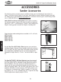
The following sander accessories may be available through your local Woodstock International Inc.
Dealer. If you do not have a dealer in your area, these products are also available through online dealers. Please call or e-mail Woodstock International Inc. Customer Service to get a current listing of dealers at: 1-800-840-8420 or at [email protected].
Df[\c;*''*Gif$Jk`Zb:c\Xe`e^GX[jare the perfect accessory
for wide belt sanders. Simply set the feed belt table to height and
feed the 15" x 20" x 1" pad through to “unload” a dirty sanding belt.
Regular cleaning greatly increases the lifespan of sanding belts.
FG<I8K@FEJ
Tough aluminum oxide sanding belts are available in 19" x 48" rolls.
;*0.0Ç-'>i`k
;*0/'Ç/'>i`k
;*0/(Ç(''>i`k
;*0/)Ç()'>i`k
;*0/*Ç(,'>i`k
Use the J_fg=fo;)).(Ifcc\iKXYc\ wherever you need extra
workpiece support. Features all-steel welded construction and measures 19" wide x 65" long. Comes with 9 ball bearing rollers and has
four independently adjustable legs for any leveling requirement.
Adjustable in height from 26 3⁄8" to 44 1⁄8" and has a 1000 lb. capacity.
The J_fg=foN(.).(?G;ljk:fcc\Zkfiis one of our top sellers and for good reasons. We have been selling this unit for years
and it has proven itself in thousands of shops around the country.
We have added a 2.5 micron top bag as standard equipment to
capture the fine dust particles that normally end up all over your
shop. Specifications: Motor 1 HP, 110/220V, single-phase with a 9/4.5
amp draw; 800 CFM air suction capacity; 5.67" static pressure; one
4" intake port; 9" balanced steel, radial fin impeller; 2.1 cubic foot
bag capacity; 15 3⁄4" x 39 3⁄4" portable base; 54 1⁄2" high with the bags
inflated; approximate shipping weight of 59 lbs.
-26-
N(/(*(/Fg\e<e[N`[\9\ckJXe[\i
D8@EK<E8E:<
>\e\iXc
Regular periodic maintenance on your machine will
ensure its optimum performance. Make a habit of
inspecting your machine each time you use it.
:_\Zb]fik_\]fccfn`e^Zfe[`k`fejXe[i\gX`ifi
i\gcXZ\n_\ee\Z\jjXip1
•
Loose mounting bolts.
Worn switch.
Worn or damaged cords and plugs.
Damaged or worn sanding belt.
Damaged, loose, or worn conveyor belt.
Any other condition that could hamper the safe
operation of this machine.
D8B< JLI< k_Xk pfli dXZ_`e\ `j
legcl^^\[ [li`e^ Xcc dX`ek\eXeZ\ gif$
Z\[li\j@]k_`jnXie`e^`j`^efi\[#j\i`$
fljg\ijfeXc`ealipdXpfZZli%
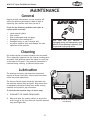
:c\Xe`e^
Use a shop vacuum to remove sawdust from the sander.
This is especially important for the internal working parts
and motor. Dust build-up around the motor is a sure way
to decrease its life span. If any essential lubrication is
removed during cleaning, re-lubricate those areas.
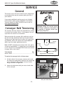
ClYi`ZXk`fe
The devices that do require bimonthly lubrication are
the elevation dovetail ways and gears. Keep these devices adequately lubricated to keep your sander running
smoothly and to protect your investment.
Rear Elevation
Dovetail Way
KfclYi`ZXk\k_\\c\mXk`fenXpj#[fk_\j\jk\gj1
(%
DISCONNECT THE SANDER FROM POWER!
)%
Raise and lower the sanding cabinet to access the
entire length of the front and rear elevation dovetail
ways (see =`^li\)+).
-27-
=`^li\)+% Elevation dovetail way (rear
way shown).
D8@EK<E8E:<
The bearings are factory lubricated and sealed and
require no further lubrication. Simply leave them alone
unless they need replacement.
N(/(*(/Fg\e<e[N`[\9\ckJXe[\i
*%
Clean away any debris and built-up grime from the
surfaces of the ways, then apply a thin coat of ISO
68 lubricant or an equivalent.
+%
Move the sanding cabinet through its entire elevation
range of motion to evenly distribute the oil.
KffcjE\\[\[
Hkp
Hex Wrench 4mm ...............................................1
KfclYi`ZXk\k_\\c\mXk`fe^\Xij#[fk_\j\jk\gj1
(%
DISCONNECT THE SANDER FROM POWER!
)%
Loosen the set screw in the elevation handwheel
hub, then remove the handwheel to access the elevation gears, as shown in =`^li\),.
*%
Use a shop rag and solvent to clean away debris and
grime from the gears, then use a brush to apply a
thin coat of NLGI #2 grease or an equivalent.
+%
Re-install the handwheel, then move the sanding
cabinet up and down to evenly distribute the grease.
=`^li\),% Elevation gears (elevation
handwheel removed).
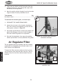
8`iI\^lcXkfi&=`ck\i
D8@EK<E8E:<
The air regulator filters the moisture from the incoming
compressed air and deposits the collected water in the
filter reservoir (see =`^li\)-).
To empty the filter reservoir, make sure there is incoming air pressure, then press the drain valve up. This will
release a flow of air and the collected water from the
reservoir.
Filter
Reservoir
Drain
Valve
=`^li\)-% Air regulator filter reservoir
and drain valve.
-28-
N(/(*(/Fg\e<e[N`[\9\ckJXe[\i
J<IM@:<
>\e\iXc
This section covers the most common service adjustments
or procedures that may be necessary during the life of
your machine.
If you require additional machine service not included
in this section, please contact Woodstock International
Technical Support at (360) 734-3482 or send e-mail to:
k\Z_$jlggfik7j_fg]fo%Y`q.
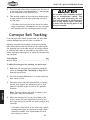
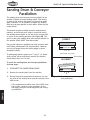
:fem\pfi9\ckK\ej`fe`e^
The conveyor belt may stretch with extended use, causing
it to slip on the conveyor rollers. If this happens, the conveyor belt will need to be re-tensioned.
D8B< JLI< k_Xk pfli dXZ_`e\ `j
legcl^^\[ [li`e^ Xcc j\im`Z\ gifZ\$
[li\j lec\jj fk_\in`j\ `ejkilZk\[ @]
k_`j nXie`e^ `j `^efi\[# j\i`flj g\i$
jfeXc`ealipdXpfZZli%
When you tension the conveyor belt, make sure you turn
the left and right adjustment bolts by the same amount.
Tensioning one side more than the other will cause tracking problems, which will require you to take additional
steps to get the sander operating correctly.
Efk\1;FEFKfm\ik`^_k\ek_\Zfem\pfiY\ck%Pfli^fXc`j
kfi\XZ_XeXggifo`dXk\ *Ð+_Xe^`e^^Xgfek_\le[\ij`[\
f]k_\Zfem\pfiY\ckj\\=`^li\). kfdXb\jli\k_\Y\ck
efcfe^\ijc`gjfek_\ifcc\ij%
KffcjE\\[\[
Hkp
Wrench 10mm ...................................................1
On both sides of the conveyor, measure and record
the reference measurement between the tension dog
on the adjustment bolt and the conveyor bracket
flange, as shown in =`^li\)/.
Loosen the adjustment bolt jam nuts on both sides
of the conveyor.
Reference
Measurement
Tension
Dog
Flange
J<IM@:<
)%
Approximately 3/4" Hanging Gap
=`^li\).% Conveyor belt hanging gap.
Kfk\ej`fek_\Zfem\pfiY\ck#[fk_\j\jk\gj1
(%
Conveyor
Belt
Sanding
Drum
Jam Nut &
Adjustment
Bolt
=`^li\)/% Conveyor tension adjustment
bolt (one side shown).
-29-
N(/(*(/Fg\e<e[N`[\9\ckJXe[\i
*%
+%
Turn both adjustment bolts clockwise one full turn at
a time until there is an approximate 3⁄4" hanging gap
on the underside of the conveyor belt.
Take another reading of the reference measurement
on both sides of the conveyor and make sure they
are the same.
— If the belt starts to track to one side or the other
when in operation, immediately turn the conveyor
F==Xe[g\i]fidk_\kiXZb`e^gifZ\[li\Y\cfn%
:fem\pfi9\ckKiXZb`e^
If the conveyor belt tracks to either side, the belt could
become damaged and you will have to replace it.
Adjusting conveyor belt tracking is a balancing process
that takes patience and trial-and-error. You must tighten
the adjusting bolt on the side the belt is tracking toward
to make the belt move to the middle of the rollers, then
loosen that same adjusting bolt to make the conveyor belt
stay centered.
KffcjE\\[\[
Hkp
Wrench 10mm ...................................................1
J<IM@:<
KfX[aljkk_\Zfem\pfiY\ckkiXZb`e^#[fk_\j\jk\gj1
(%
Make sure the conveyor belt is properly tensioned
(refer to :fem\pfi9\ckK\ej`fe`e^on GX^\)0 for
detailed instructions).
)%
Turn the conveyor FE and set it to a slow feed rate,
then watch it track.
*%
Determine which side the conveyor belt is tracking
toward, then tighten the adjustment bolt on that
side until the belt begins to track in the opposite
direction.
Efk\1KiXZb`e^Z_Xe^\jdXpkXb\XZflgc\f]d`e$
lk\jY\]fi\k_\pXi\efk`Z\XYc\%
+%
When the conveyor belt is near the middle of the
rollers, loosen the same adjustment bolt until the
belt stops moving to the side and tracks straight and
centered.
— If the belt tracks too far to the other side, tighten
the adjustment bolt as necessary to bring it back
toward the middle, then repeat Jk\gj)Æ+until
the tracking is correct.
-30-
The conveyor roller assemblies and belt
pose an entanglement hazard. Take
extra care when performing the conveyor belt tensioning or tracking procedures to keep hands, fingers, and clothing away from the moving parts of the
conveyor assembly.
N(/(*(/Fg\e<e[N`[\9\ckJXe[\i
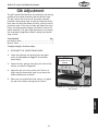
>`Y8[aljkd\ek
The gib is sandwiched between the stationary and moving
surfaces of the sander assembly and the dovetail ways.
The gib controls the accuracy of the sander assembly
movement along these ways. A tight gib makes the movement more accurate but harder to move, and will lead to
premature wear of the ways. A loose gib makes the movements and measurements sloppy, but easier to move the
sander assembly. The goal of gib adjustment is to remove
the unnecessary sloppiness without causing the dovetail
ways to bind.
KffcjE\\[\[
Hkp
Hex Wrench 4mm ...............................................1
Wrench 12mm ...................................................1
KfX[aljkk_\^`Y#[fk_\j\jk\gj1
(%
DISCONNECT THE SANDER FROM POWER!
)%
Clean and lubricate the dovetail way and gears
(refer to ClYi`ZXk`fe on GX^\). for detailed
instructions).
*%
Loosen the four gib jam nuts along the front of the
column, as shown in =`^li\)0.
+%
Adjust the gib set screws \m\ecp until there is a
slight drag on the dovetail ways as you move the
sander assembly up and down.
,%
When you are satisfied with the setting, re-tighten
the jam nuts without moving the set screws.
Gib Adjustment
Jam Nuts & Set
Screws
=`^li\)0% Gib adjustment jam nuts and
set screws.
J<IM@:<
-31-
N(/(*(/Fg\e<e[N`[\9\ckJXe[\i
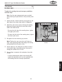
JXe[`e^;ild:fem\pfi
GXiXcc\c`jd
The sanding drum and conveyor must be parallel to one
another to obtain accurate sanding results. This setting
is made at the factory and should not have to be made
again. However, if it is necessary to adjust the sanding
drum and conveyor parallel to each other, follow the procedure below.
This process requires multiple accurate measurements,
patience, and trial-and-error. Keep in mind that having
the sanding drum parallel to the top of the conveyor belt
is critical to the sanding operation (see =`^li\30). The
goal is to bring the sanding drum and conveyor parallel to
one another within 0.005" from side-to-side.
CORRECT
Sanding Drum
Using a dial indicator is probably the most accurate method of taking measurement for this procedure. However,
you can use gauge blocks and feeler gauges to attain
acceptable results.
A
B
Conveyor Belt
A
=
B
(Within 0.005" side-to-side)
To make gauge blocks, square up a 7' long 2" x 4" board
(refer to your jointer and planer manuals for detailed
instructions), then cut it in half.
(Front View)
INCORRECT
KfZ_\Zbk_\jXe[`e^[ildXe[Zfem\pfigXiXcc\c`jd#
[fk_\j\jk\gj1
Sanding Drum
B
A
(%
DISCONNECT THE SANDER FROM POWER!
)%
Remove the sanding belt from the machine.
*%
Record the precise measurements between the lowest point of the sanding drum and the conveyor from
side-to-side.
Conveyor Belt
A
J<IM@:<
— If the measurements differ more than 0.005" from
side-to-side, continue to the procedure on the
next page to adjust the sanding drum and conveyor parallelism.
-32-
=
B
=`^li\*'% Sanding drum and conveyor
belt parallelism.
N(/(*(/Fg\e<e[N`[\9\ckJXe[\i
KffcjE\\[\[
Hkp
Hex Wrench 6mm ...............................................1
Hex Wrench 8mm ...............................................1
KfX[aljkk_\jXe[`e^[ildXe[Zfem\pfigXiXcc\c`jd#
[fk_\j\jk\gj1
Efk\1Lj\k_\jXd\d\Xjli\d\ekjpfli\Zfi[\[
n_\eZ_\Zb`e^k_\gXiXcc\c`jd`ek_\gi\m`fljgifZ\$
[li\%
(%
Loosen the four column mounting cap screws on the
right side of the column base shown in =`^li\*(.
)%
Mounting Cap Screws
Adjust the jack screws evenly to bring the sanding
drum and conveyor parallel to each other within
0.005" from side-to-side.
— To raise the left side of the sanding drum, tighten
the upper jack screw.
Jack
Screws
— To lower the left side of the sanding drum, tighten
the lower jack screw.
*%
Re-tighten the four mounting cap screws.
Mounting Cap Screws
Note: K`^_k\ek_\ZXgjZi\njaljklek`ck_\pXi\
jel^%Fm\i$k`^_k\e`e^k_\ddXpZ_Xe^\k_\j\kk`e^
XZZfdgc`j_\[n`k_k_\aXZbjZi\nj%
+%
Surface plane an 18" wide piece of stock so that it
is the same height from side-to-side, then send it
through the sander until it is flat.
,%
Use a caliper to measure this workpiece from sideto-side.
=`^li\*(% Column mounting cap and jack
screws.
— If these measurements differ more than 0.005",
repeat this procedure until you are satisfied with
the sanding drum and conveyor parallelism.
J<IM@:<
-33-
N(/(*(/Fg\e<e[N`[\9\ckJXe[\i
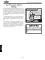
8`iGi\jjli\JX]\kp
Jn`kZ_
The sanding motor safety brake and the sanding oscillation system require at 57–60 PSI of air pressure connected
to the machine to operate. The air pressure safety switch
(see =`^li\*)) measures the amount of air pressure flowing into the machine. If the air pressure is not adequate,
the air pressure safety switch will not allow power to flow
to the sander.
Sensitivity Adjustment Screw
Minimum
Air Pressure
Adjustment Screw
& Scale
The air pressure safety switch was calibrated and set at
the factory and should not require any further adjustment. However, we recommend that you verify the settings.
Sensitivity Scale
J<IM@:<
The red pointer on the sensitivity scale should be set at
"0" on the scale, which is adjusted with the sensitivity
adjustment screw shown in =`^li\*). The minimum air
pressure scale on the right of the scale window should
read 4kg/cm2, which is adjusted with the adjustment
screw on the top of the switch.
-34-
=`^li\*)%Air pressure safety switch.
The safety devices on this machine are
there for your safety. DO NOT operate
this sander if any safety device is damaged or is not operating correctly. Otherwise, serious personal injury could
result.
N(/(*(/Fg\e<e[N`[\9\ckJXe[\i
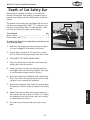
;\gk_f]:lkJX]\kp9Xi
When properly adjusted, the depth of cut safety bar
prevents the operator from sanding a workpiece that is
beyond a safe height and that could become a kickback
hazard.
The position of this safety bar (see =`^li\**) was set by
the factory at approximately 0.047" (3⁄64") above the lowest point of the sanding drum. For safe operation, make
sure that this safety bar remains at this setting.
Hex Bolts
KffcjE\\[\[
Hkp
Wrench 10mm ...................................................1
Feeler Gauge 0.047" (3⁄64") ....................................1
KfX[aljkk_\[\gk_f]ZlkjX]\kpYXikfk_\]XZkfipj\k$
k`e^#[fk_\j\jk\gj1
(%
Make sure the sanding drum and conveyor are parallel (refer to GX^\*) for detailed instructions).
Surface plane and sand an 18" wide piece of stock
until it is flat and the same height from side-to-side.
*%
DISCONNECT THE SANDER FROM POWER!
+%
Open the sanding belt access door and remove the
sanding belt from the machine.
5.
Loosen the three hex bolts securing the safety bar
(see =`^li\**), raise the bar up slightly, then tighten the hex bolts enough to hold it in place.
-%
Place the workpiece from Jk\g)under the sanding
drum, then lower the sanding cabinet until the sanding drum is just touching the workpiece.
.%
Remove the workpiece from under the sanding drum
and position it directly under the depth of cut safety
bar.
/%
Loosen the three hex bolts securing the safety bar,
then position the bar so that it is 0.047" (3⁄64") above
the workpiece from side-to-side, then fully re-tighten the hex bolts to secure it.
0%
Re-install the sanding belt and secure the access
door.
-35-
=`^li\**% Depth of cut safety bar.
J<IM@:<
)%
Safety Bar
N(/(*(/Fg\e<e[N`[\9\ckJXe[\i
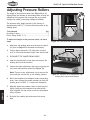
8[aljk`e^Gi\jjli\Ifcc\ij
The height of the pressure rollers (see =`^li\*+) is set
slightly below the bottom of the sanding drum to keep the
workpiece firmly against the conveyor belt as it passes
through the sander, preventing workpiece kickback.
The pressure roller height was set by the factory at
approximately 0.063" (1⁄16") below the lowest point of the
sanding drum.
Pressure Rollers
KffcjE\\[\[
Hkp
Hex Wrench 4mm ...............................................1
Feeler Gauge 0.063" (1⁄16") ....................................1
KfX[aljkk_\_\`^_kf]k_\gi\jjli\ifcc\ij#[fk_\j\
jk\gj1
(%
Make sure the sanding drum and conveyor are parallel (refer to GX^\*) for detailed instructions).
)%
Surface plane and sand a 18" wide piece of stock
until it is flat and the same height from side-to-side.
*%
DISCONNECT THE SANDER FROM POWER!
+%
Open the sanding belt access door and remove the
sanding belt from the machine.
,%
Loosen the eight adjustment cap screws securing the
front and rear pressure rollers (see =`^li\*,).
J<IM@:<
Note: K_\i\Xi\]fliX[aljkd\ekZXgjZi\njfek_\
]ifekXe[]flifek_\i\Xif]k_\jXe[`e^ZXY`e\k%
-%
Place the workpiece from Jk\g) under the sanding
drum, then elevate the sander assembly so that the
sanding drum is 0.063" (1⁄16") above the workpiece.
.%
Manually adjust the pressure rollers so that they are
lightly resting on the workpiece from side-to-side,
then retighten the cap screws to secure the pressure
rollers in place.
/%
Re-install the sanding belt and secure the access
door.
-36-
=`^li\*+% Front and rear pressure rollers.
Cap Screws
=`^li\*,% Pressure roller adjustment cap
screws (front cap screws shown).
N(/(*(/Fg\e<e[N`[\9\ckJXe[\i
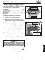
I\gcXZ`e^:fem\pfi9\ck
If the conveyor belt becomes damaged or too worn to properly adjust the tension, you must replace it.
Sander Assembly
Mounting Brackets
KffcjE\\[\[
Hkp
Hex Wrench 4mm ...............................................1
Hex Wrench 5mm ...............................................1
Wrench 10mm ...................................................1
Wrench 12mm ...................................................1
Kfi\gcXZ\k_\Zfem\pfiY\ck#[fk_\j\jk\gj1
Roller Guards
(%
DISCONNECT THE SANDER FROM POWER!
)%
Remove the cap screws and flat washers securing
the front and rear conveyor roller guards (see =`^li\
*-), then remove the guards.
=`^li\*-% Sander assembly mounting
brackets and conveyor roller guards.
*%
Loosen the conveyor tension jam nuts on either side
of the conveyor (see =`^li\*.), then release the
tension on the conveyor belt by loosening the tension adjustment bolts.
Cap Screws
+%
Remove the three cap screws securing the c\]k front
roller bracket shown in =`^li\*., then, while supporting the front conveyor roller assembly with one
hand, remove the bracket.
,%
Carefully pull the front conveyor roller assembly
from the conveyor belt.
Note: 8kk_`jgf`ek#k_\]ifekifcc\iYiXZb\k`jjk`cc
XkkXZ_\[kfk_\Zfem\pfifek_\i`^_kj`[\Xe[n`cc
jkXp`egcXZ\%
Roller Bracket
Tension Adjustment
Bolt & Jam Nut
=`^li\*.% Roller bracket mounting cap
screws and conveyor tension adjustment
bolt.
NOTICE
Take care not to scratch or dent the surface of
the front conveyor roller as you remove it from
the sander. Damage to the conveyor roller could
result in premature wear of the conveyor belt.
-37-
J<IM@:<
Continued on next page
N(/(*(/Fg\e<e[N`[\9\ckJXe[\i
-%
Remove the three cap screws securing the left rear
conveyor roller bracket to the conveyor support, but
leave the roller assembly and the bracket in place,
as shown in =`^li\*/.
Rear Conveyor
Roller Bracket
Hex Bolt
(1 of 2)
NOTICE
8]k\i cffj\e`e^ k_\ c\]k Zfem\pfi ifcc\i YiXZb\k#
k_\ i\Xi Zfem\pfi ifcc\i Xjj\dYcp `j jlggfik\[ Yp
`kj XkkXZ_d\ek kf k_\ Zfem\pfi dfkfi Xjj\dYcp%
?fn\m\i#kfXmf`[[XdX^`e^k_\ifcc\iXjj\dYcp#;F
EFKglklee\Z\jjXipjkiX`efek_`jXjj\dYcp%
.%
Loosen, but do not remove, the upper cap screws on
the left side of the conveyor assembly that secure
the sander assembly to the mounting brackets (see
=`^li\*- on GX^\*.).
=`^li\*/% Rear conveyor roller bracket
unattached from the conveyor support.
Efk\1Cffj\e`e^k_\j\ZXgjZi\njn`cci\c`\m\k_\
jkiX`efek_\YiXZb\kj]fik_\e\okjk\g%
/%
Remove the two hex bolts and flat washers on the
left side of the conveyor that secure the sander
assembly mounting brackets to the cabinet stand
(see =`^li\*/).
0%
With assistance, lift the left side of the conveyor
assembly up approximately 1", then remove the conveyor belt, as shown in =`^li\*0.
('% Slide the new conveyor belt onto the conveyor
assembly, then re-install the parts removed or loosened in reverse order.
((% Re-tension the conveyor belt, and adjust the tracking (refer to GX^\j)0*').
J<IM@:<
()% Re-adjust the sanding drum and conveyor parallelism
(refer to GX^\*)).
-38-
=`^li\*0% Removing the conveyor belt
from the machine.
N(/(*(/Fg\e<e[N`[\9\ckJXe[\i
<c\Zki`ZXcJX]\kp@ejkilZk`fej
These pages are current at the time of printing. However, in the spirit of improvement, we may make
changes to the electrical systems of future machines. Study this diagram carefully. If you notice differences between your machine and these wiring diagrams, call Woodstock International Technical Support
at (360) 734-3482.
(% J?F:B?8Q8I;%9^hXdccZXii]ZedlZg
[gdbi]ZbVX]^cZWZ[dgZhZgk^X^c\ZaZXig^XVa
XdbedcZcih#IdjX]^c\ZaZXig^[^ZYeVgihl^aa
gZhjai^ceZghdcVa^c_jgn^cXajY^c\Wjicdi
a^b^iZYidhZkZgZWjgch!ZaZXigdXji^dc!dg
YZVi]#
-% DFKFIN@I@E>%I]Zbdidgl^g^c\h]dlc
^ci]ZhZY^V\gVbhVgZXjggZciVii]Zi^bZ
d[eg^ci^c\!Wji^ibVncdibViX]ndjg
bVX]^cZ#6alVnhjhZi]Zl^g^c\Y^V\gVb
^ch^YZi]Zbdidg_jcXi^dcWdm#
7. EXPERIENCING DIFFICULTIES. >[ Vi Vcn
i^bZndjVgZZmeZg^ZcX^c\Y^[[^Xjai^ZhjcYZg"
hiVcY^c\ i]Z ^c[dgbVi^dc ^cXajYZY ^c i]^h
hZXi^dc! XdciVXi djg IZX]c^XVa Hjeedgi Vi
*,%*)+".++(#
)% :@I:L@KI<HL@I<D<EKJ%You MUST follow the specifications and direction of the
<C<:KI@:8ChZXi^dcon GX^\('. @]pfl
Xi\lejli\XYflkk_\n`i`e^Zf[\j`e
pfliXi\XfipflgcXekfZfee\Zkpfli
dXZ_`e\kfXj_Xi\[Z`iZl`k#ZfejlckX
hlXc`]`\[\c\Zki`Z`Xe%
NOTICE
*% >IFLE;<;:@I:L@K%:aZXigdXji^dcdg[^gZ
XdjaYgZhjai^[i]ZbVX]^cZ^hcdi\gdjcYZY
VcY^chiVaaZY^cXdbea^VcXZl^i]ZaZXig^XVa
XdYZh#8dbea^VcXZBJHIWZkZg^[^ZYWnV
fjVa^[^ZYZaZXig^X^Vc#
K_\g_fkfjXe[[`X^iXdj`eZcl[\[`ek_`jj\Z$
k`feXi\Y\jkm`\n\[`eZfcfi%PflZXem`\n
k_\j\gX^\j`eZfcfiXknnn%j_fg]fo%Y`q%
COLOR KEY
J?F:B?8Q8I;
;`jZfee\Zkgfn\iY\]fi\
j\im`Z`e^\c\Zki`ZXcgXikj%
KflZ_`e^\c\Zki`]`\[gXikj
n`cci\jlck`ej\m\i\Yliej#
\c\ZkifZlk`fe#fi[\Xk_%
BLACK
Bk
WHITE
Wt
GREEN
Gn
RED
Rd
BLUE
Bl
YELLOW
Yl
J<IM@:<
-39-
N(/(*(/Fg\e<e[N`[\9\ckJXe[\i
<c\Zki`ZXcN`i`e^Fm\im`\n
8
9
:
;
<
Refer to GX^\++.
8
:
Air Pressure
Brake Solenoid
(Diagram: GX^\+*)
Air Pressure
Safety Switch
(Diagram: GX^\+*)
9
Electrical Box
& Control Panel
(Photo: GX^\+(,
Diagram: GX^\+))
J<IM@:<
<
Conveyor Motor
(Diagram: GX^\+*)
;
Sanding Motor
(Diagram: GX^\+*)
READ ELECTRICAL SAFETY
ON PAGE 39!
-40-
electrical box photo
N(/(*(/Fg\e<e[N`[\9\ckJXe[\i
<c\Zki`ZXc9fo:fekifcGXe\c
Conveyor DC
Motor Control
Contactor &
Overload Relay
=`^li\+'% Electrical box wiring (Diagram: GX^\+)).
Power Lamp
Amperage Load Meter
Sanding Motor
ON Button
Conveyor
Feed Rate
Dial
Emergency
Stop Button
Conveyor ON/
OFF Switch
-41-
READ ELECTRICAL SAFETY
ON PAGE 39!
J<IM@:<
=`^li\+(% Control panel wiring (Diagram: GX^\+)).
electrical box diagram
N(/(*(/Fg\e<e[N`[\9\ckJXe[\i
<c\Zki`ZXc9fo:fekifcGXe\cN`i`e^;`X^iXd
To Conveyor Motor
(GX^\+*)
Wt Bk
Bk Rd
To Air Pressure
Safety Switch
(GX^\+*)
<gdjcY
Bk
Rd Wt
Rd
Wt
A1
A2
Rd
Bk
Bk
Bk
Bk
1L1
3L2
5L3
17
NHD C-09D
220V
2T1
4T2
Rd
DC Motor Control
(Conveyor Motor)
13NO
To Air Pressure
Brake Solenoid
(GX^\+*)
18
Wt
14NO
6T3
Bk
Bk
Rd
Wt
Wt
Rd
Bk
Wt
Gn
Rd
NHD NTH-17
Rd
14
15
Power
Light
16
R
O
17
Ground
To Sanding Motor
(GX^\+*)
Bk
Wt
Gn
X1
Rd
98
97
2T1
96
X2
95
4T2
Rd
6T3
Rd
Gn
Wt
Wt
Ground
Bk
Bk
Wt
Bk
Sanding Motor
Rd
ON Button
Bk
Rd
Bk
Amp Load
Meter
4
3
Rd
Rd
Hot
Hot
J<IM@:<
Wt
Bk
Coveyor
ON/OFF
Switch
Rd
Wt
Bk
Wt
Conveyor
Variable Speed
Dial
READ ELECTRICAL SAFETY
ON PAGE 39!
Emergency Stop
Button
Bk
3
4
Bk
Rd
1
2
Rd
Ground
Gn
Bk
G
6-20 Plug
(as recommended)
-42-
electrical components
N(/(*(/Fg\e<e[N`[\9\ckJXe[\i
<c\Zki`ZXc:fdgfe\ekj
Sanding Motor
Bk
Run Capacitor
50M 250V
Bk
Gn
Wt
Electrical Box
Start Capacitor
400M 125V
Bk
=`^li\+)% Sanding motor wiring.
=`^li\+,% Sanding motor wiring diagram.
Gn
Bk
Bk
Wt
Electrical Box
Conveyor
Motor
=`^li\+*% Conveyor motor wiring.
Bk
=`^li\+-% Conveyor motor wiring diagram.
Air Pressure
Safety Switch
Air Pressure Safety Switch
Bk
Air Pressure
Brake
Solenoid
Electrical Box
Electrical Box
=`^li\++% Air pressure safety switch and brake
solenoid.
Air Pressure
Brake Solenoid
=`^li\+.% Air pressure safety switch and brake
solenoid wiring diagrams.
-43-
READ ELECTRICAL SAFETY
ON PAGE 39!
J<IM@:<
Bk
pneumatic system
N(/(*(/Fg\e<e[N`[\9\ckJXe[\i
Ge\ldXk`ZJpjk\dFm\im`\n
Air Pressure Safety Switch
(I\](0/ on GX^\+.)
4-Way Valve
(I\](0, on GX^\+.)
Oscillation Cylinder
(I\])*, on GX^\+.)
Air Regulator
(I\](+) on GX^\+.)
Oscillation Valve
(I\])(. on GX^\+.)
Air Pressure
Brake Solenoid
(I\](00 on GX^\+.)
J<IM@:<
Sanding Motor
Brake Unit
(I\](+) on GX^\+.)
Shop Air
Compressor
Refer to GX^\+*.
-44-
N(/(*(/Fg\e<e[N`[\9\ckJXe[\i
KiflYc\j_ffk`e^
This section covers the most common problems and corrections with this type of
machine. N8IE@E>;FEFKdXb\XepX[aljkd\ekjlek`cgfn\i`j[`jZfee\Zk\[Xe[
dfm`e^gXikj_Xm\Zfd\kfXZfdgc\k\jkfg
GIF9C<D
GFJJ@9C<:8LJ<
:FII<:K@M<8:K@FE
Machine does not start 1. Switch disabling key removed.
or a breaker trips.
2. Emergency stop push-button engaged/
faulty.
3. Power supply switched OFF or at fault.
4. Plug/receptacle at fault/wired wrong.
5. Start capacitor at fault.
6. Air pressure safety switch open/at
fault.
7. Motor connection wired wrong.
8. Thermal overload relay has tripped.
9. Wall circuit breaker tripped.
1. Install switch disabling key.
2. Rotate button to reset/replace it.
Ensure power supply is on/has correct voltage.
Test for good contacts; correct the wiring.
Test/replace if faulty.
Adjust air pressure safety switch; replace if
faulty.
7. Correct motor wiring connections (Page 43).
8. Reset; adjust trip load dial if necessary; replace.
9. Ensure circuit size is correct/replace weak breaker.
10. Contactor not energized/has poor con- 10. Test all legs for power/replace if faulty.
tacts.
11. Check/fix broken, disconnected, or corroded
11. Wiring open/has high resistance.
wires.
12. Motor ON button or ON/OFF switch at 12. Replace button/switch.
fault.
13. Test/repair/replace.
13. Motor at fault.
Machine stalls
underpowered.
or
3.
4.
5.
6.
is 1. Workpiece material not suitable for 1. Only sand wood/ensure moisture is below 20%.
machine.
2. Depth of cut too much; feed rate to 2. Properly adjust depth of cut (Page 22); reduce
conveyor feed rate.
fast.
3. Clear blockages, seal leaks, use smooth wall duct,
3. Dust collection ducting problem.
eliminate bends, close other branches.
4. Test/repair/replace.
4. Run capacitor at fault.
5. Wire motor correctly (Page 43).
5. Motor wired incorrectly.
6. Test for good contacts/correct wiring.
6. Plug/receptacle at fault.
7. Test/repair/replace.
7. Motor bearings at fault.
8. Clean/replace sandpaper; reduce feed rate/sand8. Machine undersized for task.
ing depth of cut (Page 22)
9. Contactor not energized/has poor con- 9. Test all legs for power/replace if faulty.
tacts.
10. Clean motor, let cool, and reduce workload.
10. Motor overheated.
11. Test/repair/replace.
11. Motor at fault.
2. Machine incorrectly mounted.
3. Motor fan rubbing on fan cover.
4. Motor bearings at fault.
5. Conveyor gearbox at fault.
-45-
1. Inspect/replace damaged bolts/nuts, and re-tighten with thread locking fluid.
2. Tighten mounting bolts; relocate/shim machine.
3. Fix/replace fan cover; replace loose/damaged
fan.
4. Test by rotating shaft; rotational grinding/loose
shaft requires bearing replacement.
5. Rebuild gearbox for bad gear(s)/bearing(s).
J<IM@:<
Machine has vibration or 1. Motor or component loose.
noisy operation.
N(/(*(/Fg\e<e[N`[\9\ckJXe[\i
GIF9C<D
GFJJ@9C<:8LJ<
:FII<:K@M<8:K@FE
Grit rubs off sanding 1. Sanding belt has been stored in an incor- 1. Store sanding belts away from extremely dry/
belt easily.
moist environment or hot temperatures.
rect environment.
2. Sanding belt has been folded or 2. Store sanding belt flat, not folded or bent.
smashed.
1. Reduce sanding depth of cut (Page 22) or use
coarser grit sandpaper.
2. Sanding softwood or workpiece with high 2. Use different stock, or accept the characteristics
of the stock and plan on cleaning/replacing belts
residue.
frequently; remove residue, such as varnish/
paint, before sanding.
Sanding belt clogs quick- 1. Sanding depth of cut too aggressive.
ly or workpiece burns.
Burn
marks
workpiece.
1. Use a coarser grit sanding belt.
on 1. Using too fine of sanding grit.
2. Properly adjust depth of cut (Page 22).
2. Sanding depth of cut too aggressive.
3. Workpiece moves too slow through sand- 3 Increase conveyor feed rate.
er.
Glazed sanding surface.
1. Sanding wet stock.
2. Sanding stock with high residue.
1. Only sand wood/ensure moisture is below 20%.
2. Remove residue, such as varnish or paint, before
sanding, or accept the characteristics of the stock
and plan on cleaning/replacing sanding belts frequently.
Workpiece slips on con- 1. Conveyor belt dirty or worn.
veyor.
2. Pressure rollers not adjusted properly.
1. Clean/replace conveyor belt.
2. Properly adjust pressure roller height (Page 36).
Uneven workpiece thick- 1. Sanding drum not parallel to conveyor.
ness from side-to-side.
1. Adjust the sanding belt to conveyor parallelism
(Page 32).
2. Replace conveyor belt (Page 37).
J<IM@:<
2. Conveyor belt is worn.
-46-
213
E
103
G8IKJ
-47-
199
195
194
203 193 192
219
193
187
189
196
190
197
F
201
191 187
186
189
187
188
259
258
I
176-6
179
185
202
193
184
175
143
205
135
168 174
181 183
112
169
111
182
134
176
139
180
177 178
137 138
173
172
171
176-4 176-3 176-2 176-1
170
253
133
231
144
145
147
198
132 140 141
176-5
131
155 116
240
204
113
111
160
112
135
113-1
109
159
238
161 C 158 107 108
252
164
162
F
110
103
256
106 104
163
122 250
201
105
114
C
115
D
257
249
167 205
135
B
103
116
103
244
G
H
165
117
102
253 166
101
G
247
B
124
243
125
118
D
103
112
254
126
122
242
231
127
135
A
245
117
122
241 111
H 129
251 246
A
262
119
200
128
120
121
123
261
116
260
150
151 I
152
203
175
137
220
210
142 130
209
149 148
208
153
207 156
154
206 157
217
218
219 142
136
214
248
146
205
104 121
222
221
146
220
207
212 211
122
215
216
127
146
228
230 207
112
171 231 103
159
235 229
226
234
236
103
233
227 171
205
232
160
172 167
E
239
237
104
121
120 224
121
225
121 225
120
223
N(/(*(/Fg\e<e[N`[\9\ckJXe[\i
parts
G8IKJ
DX`e9i\Xb[fne
N(/(*(/Fg\e<e[N`[\9\ckJXe[\i
G8IKJ
DX`eGXikjC`jk
REF
PART #
DESCRIPTION
REF
PART #
DESCRIPTION
101
102
103
104
105
106
107
108
109
110
111
112
113
113-1
114
115
116
117
118
119
120
121
122
123
124
125
126
127
128
129
130
131
132
133
134
135
136
137
138
139
140
141
142
143
144
145
146
147
148
149
X1813101
X1813102
XPS16M
X1813104
X1813105
XPK12M
X1813107
X1813108
XPSS03
X1813110
XPB19
XPW06
X1813113
X1813113-1
XPSB26M
X1813115
XPSB02
X1813117
X1813118
X1813119
X1813120
XPR18M
XPN05
XPB10
X1813124
X1813125
XPSS39
XPLN02
X1813128
X1813129
X1813130
XPSB31M
XPSB61M
X1813133
X1813134
XPSB06
X1813136
XP51102
XPRP39M
X1813139
X1813140
X1813141
XP51105
X1813143
X1813144
X1813145
XPSB04
X1813147
X1813148
X1813149
CONVEYOR TABLE
CONVEYOR ROLLER BRACKET LR
PHLP HD SCR M8-1.25 X 16
BALL BEARING 6003ZZNR
CONVEYOR ROLLER REAR
KEY 5 X 5 X 30
CONVEYOR ROLLER BRACKET RR
LOCK COLLAR
SET SCREW 1/4-20 X 3/8
CONVEYOR MOTOR BRACKET
HEX BOLT 1/4-20 X 1/2
FLAT WASHER 1/4
CONVEYOR MOTOR
CONVEYOR MOTOR WORM
CAP SCREW M6-1 X 12
CONVEYOR ROLLER GUARD REAR
CAP SCREW 10-24 X 3/8
CONVEYOR ROLLER BRACKET FRONT
CONVEYOR ROLLER FRONT
CONVEYOR ROLLER SHAFT FRONT
BALL BEARING 6203ZZ
EXT RETAINING RING 17MM
HEX NUT 1/4-20
HEX BOLT 1/4-20 X 2
CONVEYOR BELT
LOCK COLLAR
SET SCREW 1/4-20 X 1-1/4
LOCK NUT 1/4-20
CONVEYOR ROLLER GUARD FRONT
SUPPORT LEG
SUPPORT FRAME
CAP SCREW M8-1.25 X 25
CAP SCREW M10-1.5 X 20
ELEVATION SCALE
WORM ROD BRACKET
CAP SCREW 1/4-20 X 1
WORM ROD
THRUST BEARING 51102
ROLL PIN 4 X 20
SPECIAL LOCK NUT
HANDWHEEL
HANDLE
THRUST BEARING 51105
ELEVATION LEADSCREW
WORM SHAFT
WORM GUARD
CAP SCREW 1/4-20 X 1/2
PLUG
SPANNER NUT
ELEVATION LEADSCREW BRACKET
150
151
152
153
154
155
156
157
158
159
160
161
162
163
164
165
166
167
168
169
170
171
172
173
174
175
176
176-1
176-2
176-3
176-4
176-5
176-6
177
178
179
180
181
182
183
184
185
186
187
188
189
190
191
192
193
XPW04M
XPLW06M
XPLN05M
XPSB11
X1813154
X1813155
XPSB03
X1813157
XPSS19
XPN02
X1813160
X1813161
XP6205
X1813163
X1813164
XPB20M
X1813166
XPSB30
X1813168
XPB03
XPB12
XPLW01
XPW07
X1813173
X1813174
XPSS02
X1813176
X1813176-1
X1813176-2
X1813176-3
X1813176-4
X1813176-5
X1813176-6
X1813177
X1813178
X1813179
X1813180
X1813181
X1813182
X1813183
X1813184
X1813185
X1813186
XPHTEK6
X1813188
X1813189
X1813190
X1813191
X1813192
X1813193
FLAT WASHER 10MM
LOCK WASHER 10MM
LOCK NUT M10-1.5
CAP SCREW 5/16-18 X 1-1/4
LOWER SANDING BELT FRAME
POINTER
CAP SCREW 5/16-18 X 1
GIB
SET SCREW 5/16-18 X 1-1/4
HEX NUT 5/16-18
LOCK HANDLE
SANDING DRUM
BALL BEARING 6205ZZ
BEARING HOUSING
AUXILIARY SUPPORT PLATE
HEX BOLT M8-1.25 X 35
SPACER
CAP SCREW 5/16-18 X 1/2
MOTOR MOUNT
HEX BOLT 5/16-18 X 1
HEX BOLT 5/16-18 X 1-1/4
LOCK WASHER 5/16
FLAT WASHER 5/16
ELECT. BOX SUPPORT BRACKET
COUPLER
SET SCREW 5/16-18 X 3/8
MOTOR 3HP 220V 1PH
MOTOR FAN COVER
MOTOR FAN
CAPACITOR COVER
R CAP. 50M 250V 1-7/8 X 3-1/4
S CAP. 400M 125V 1-7/8 X 3-1/4
MOTOR JUNCTION BOX
SANDING MOTOR BRAKE UNIT
STRAIN RELIEF
ELECTRICAL BOX
CONTROL PANEL
POWER SWITCH
CONVEYOR SPEED CONTROL
EMERGENCY STOP BUTTON
SANDING MOTOR BUTTON
POWER INDICATION LAMP
AMPERAGE METER
TAP SCREW #10 X 3/8
POWER CORD 14GA 6-1/2FT
STRAIN RELIEF
DC MOTOR SPEED CONTROLLER
ELECTRIC BOX UPPER COVER
AIR REGULATOR
TUBE CONNECTOR
-48-
N(/(*(/Fg\e<e[N`[\9\ckJXe[\i
DX`eGXikjC`jk
REF
PART #
DESCRIPTION
REF
PART #
DESCRIPTION
194
195
196
197
198
199
200
201
202
203
204
205
206
207
208
209
210
211
212
213
214
215
216
217
218
219
220
221
222
223
224
225
226
227
X1813194
X1813195
X1813196
X1813197
X1813198
X1813199
XPS10
XPLN04
X1813202
X1813203
X1813204
XPW01M
X1813206
XPLW02
XPSB01
X1813209
XP51106
X1813211
X1813212
X1813213
X1813214
XPSS50
XPW06
X1813217
X1813218
XPSB21M
X1813220
X1813221
X1813222
X1813223
X1813224
X1813225
X1813226
X1813227
CONNECTING TUBE
4-WAY VALVE
AIR INLET 1/4 NPT
CONNECTOR
AIR PRESSURE SAFETY SWITCH
AIR PRESSURE BRAKE SOLENOID
PHLP HD SCR 10-24 x 1-1/2
LOCK NUT 10-24
AIR PLUG
PNEUMATIC MUFFLER
SUPPORT ARM
FLAT WASHER 8MM
ELEVATION ROD GUIDE
LOCK WASHER 1/4
CAP SCREW 1/4-20 X 5/8
COMPRESSION SPRING
THRUST BEARING 51106
LOCK COLLAR
SANDING BELT ELEVATION ROD
CRANK LEFT
CRANK RIGHT
SET SCREW 1/4-20 X 2
FLAT WASHER 1/4
OSCILLATION VALVE
COMPRESSION SPRING
CAP SCREW M4-.7 X 30
PIPE JOINT
UPPER ROLLER SUPPORT FRAME
UPPER ROLLER BRACKET
UPPER ROLLER
UPPER ROLLER SHAFT
OSCILLATION SENSOR PLATE
SUPPORT BRACKET
SUPPORT PLATE
228
229
230
231
232
233
234
235
236
237
238
239
240
241
242
243
244
245
246
247
248
249
250
251
252
253
254
256
257
258
259
260
261
262
X1813228
X1813229
XP608
XPW01M
X1813232
XPS06M
X1813234
X1813235
X1813236
X1813237
X1813238
X1813239
X1813240
X1813241
X1813242
X1813243
X1813244
X1813245
X1813246
X1813247
XPS76M
X1813249
X1813250
X1813251
X1813252
XPB07M
X1813254
X1813256
X1813257
X1813258
X1813259
X1813260
XPN08
XPW04M
SPECIAL SCREW
SPACER
BALL BEARING 608ZZ
FLAT WASHER 8MM
BRACKET
PHLP HD SCR M5-.8 X 20
GEAR WASHER 5MM
OSCILLATION CYLINDER
PIPE JOINT
SANDING BELT
LEVER
KNOB
SANDING BELT GUARD
DEPTH OF CUT SAFETY PLATE
PRESSURE ROLLER
PRESSURE ROLLER BUSHING
PRESSURE ROLLER BRACKET R.
PRESSURE ROLLER BRACKET L.
ROLLER SUPPORT BRACKET L.
ROLLER SUPPORT BRACKET R.
PHLP HD SCR M8-1.25 X 12
COMPRESSION SPRING
SIDE COVER LOCK KNOB
SIDE COVER
HINGE PIN
HEX BOLT M8-1.25 X 25
CABINET
DOOR
DOOR LOCK
CONTACTOR NHD C-090 220V
OL RELAY NHD NTH-17 14-17A
STAND FOOT
HEX NUT 3/8-16
FLAT WASHER 10MM
G8IKJ
-49-
N(/(*(/Fg\e<e[N`[\9\ckJXe[\i
CXY\cGcXZ\d\ek
JX]\kp cXY\cj nXie XYflk dXZ_`e\ _XqXi[j Xe[ _fn kf gi\m\ek dXZ_`e\ [XdX^\ fi `ealip% K_\
fne\i f] k_`j dXZ_`e\ DLJK dX`ekX`e k_\ fi`^`eXc cfZXk`fe Xe[ i\X[XY`c`kp f] Xcc cXY\cj fe k_`j
dXZ_`e\% @] Xep cXY\c `j i\dfm\[ fi Y\Zfd\j lei\X[XYc\# I<GC8:< k_Xk cXY\c Y\]fi\ Xccfn`e^
k_\dXZ_`e\kf\ek\ij\im`Z\X^X`e%:fekXZkNff[jkfZb@ek\ieXk`feXc#@eZ%Xk(*-').*+$*+/)fi
nnn%j_fg]fokffcj%Zfdkffi[\ie\ncXY\cj%
302
301
303
304
312
305
311
310
306
309
306
314
308
Back of Machine
313
307
315
PART #
DESCRIPTION
REF
PART #
DESCRIPTION
X1813301
X1813302
X1813303
X1813304
XPLABEL-63
X1813306
XLABEL-04
D3376
MACHINE ID LABEL
MODEL NUMBER LABEL
ELEVATION HANDWHEEL LABEL
CONTROL PANEL LABEL
DISCONNECT WARNING LABEL
HAZARD AREA LABEL
ELECTRICITY LABEL
SHOP FOX NAMEPLATE-MEDIUM
309
310
311
312
313
314
315
XPLABEL-55
XPLABEL-37
XPLABEL-12A
X1813312
XPPAINT-7
XPPAINT-1
X1813315
ENTANGLEMENT HAZARD LABEL
EYE/LUNG HAZARD LABEL VERT
READ MANUAL LABEL VERT
HAND INJURY LABEL VERT
SHOPFOX BLACK TOUCH UP PAINT
SHOPFOX WHITE TOUCH UP PAINT
SHOPFOX BLACK STRIPE LABEL
G8IKJ
REF
301
302
303
304
305
306
307
308
-50-
N(/(*(/Fg\e<e[N`[\9\ckJXe[\i
NXiiXekpI\^`jkiXk`fe
Name ___________________________________________________________________________________
Street __________________________________________________________________________________
City _________________________ State ___________________________Zip ________________________
Phone # ______________________ Email___________________________Invoice # ___________________
Model #_________Serial #______________Dealer Name__________________Purchase Date___________
K_\]fccfn`e^`e]fidXk`fe`j^`m\efeXmfclekXipYXj`j%@kn`ccY\lj\[]fidXib\k`e^gligfj\jkf_\cglj
[\m\cfgY\kk\igif[lZkjXe[j\im`Z\j%F]Zflij\#Xcc`e]fidXk`fe`jjki`ZkcpZfe]`[\ek`Xc%
(%
)%
CUT ALONG DOTTED LINE
*%
How did you learn about us?
_____ Advertisement
_____ Mail Order Catalog
_____ Friend
_____ Website
____ Local Store
____ Other:
How long have you been a woodworker/metalworker?
_____ 0-2 Years
_____ 2-8 Years
____ 8-20 Years
_____ 20+ Years
How many of your machines or tools are Shop Fox?
_____ 0-2
_____ 3-5
____ 6-9
_____ 10+
+%
Do you think your machine represents a good value?
_____ Yes
____ No
,%
Would you recommend Shop Fox products to a friend?
_____ Yes
____ No
-%
What is your age group?
_____ 20-29
_____ 50-59
.%
/%
What is your annual household income?
_____ $20,000-$29,000
_____ $30,000-$39,000
_____ $50,000-$59,000
_____ $60,000-$69,000
____ 40-49
____ 70+
____ $40,000-$49,000
____ $70,000+
Which of the following magazines do you subscribe to?
____
____
____
____
____
____
____
____
____
____
0%
_____ 30-39
_____ 60-69
Cabinet Maker
Family Handyman
Hand Loader
Handy
Home Shop Machinist
Journal of Light Cont.
Live Steam
Model Airplane News
Modeltec
Old House Journal
____
____
____
____
____
____
____
____
____
____
Popular Mechanics
Popular Science
Popular Woodworking
Practical Homeowner
Precision Shooter
Projects in Metal
RC Modeler
Rifle
Shop Notes
Shotgun News
____
____
____
____
____
____
____
____
____
Today’s Homeowner
Wood
Wooden Boat
Woodshop News
Woodsmith
Woodwork
Woodworker West
Woodworker’s Journal
Other:
Comments:VVVVVVVVVVVVVVVVVVVVVVVVVVVVVVVVVVVVVVVVVVVVVVVVVVVVVVVVVVVVVVVVVV
VVVVVVVVVVVVVVVVVVVVVVVVVVVVVVVVVVVVVVVVVVVVVVVVVVVVVVVVVVVVVVVVVVVVVVVVVVVVV
VVVVVVVVVVVVVVVVVVVVVVVVVVVVVVVVVVVVVVVVVVVVVVVVVVVVVVVVVVVVVVVVVVVVVVVVVVVVV
VVVVVVVVVVVVVVVVVVVVVVVVVVVVVVVVVVVVVVVVVVVVVVVVVVVVVVVVVVVVVVVVVVVVVVVVVVVVV
VVVVVVVVVVVVVVVVVVVVVVVVVVVVVVVVVVVVVVVVVVVVVVVVVVVVVVVVVVVVVVVVVVVVVVVVVVVVV
FOLD ALONG DOTTED LINE
Place
Stamp
Here
NFF;JKF:B@EK<IE8K@FE8C@E:%
G%F%9FO)*'0
9<CC@E>?8D#N80/)).$)*'0
FOLD ALONG DOTTED LINE
TAPE ALONG EDGES--PLEASE DO NOT STAPLE
N8II8EKP
N8II8EKP
Nff[jkfZb@ek\ieXk`feXc#@eZ%nXiiXekjXccJ_fg=fodXZ_`e\ipkfY\]i\\f][\]\Zkj]ifdnfibdXej_`g
Xe[dXk\i`Xcj]fiXg\i`f[f]knfp\Xij]ifdk_\[Xk\f]fi`^`eXcgliZ_Xj\Ypk_\fi`^`eXcfne\i%
K_`jnXiiXekp[f\jefkXggcpkf[\]\Zkj[l\[`i\Zkcpfi`e[`i\Zkcpkfd`jlj\#XYlj\#e\^c`^\eZ\fi
XZZ`[\ekj#cXZbf]dX`ek\eXeZ\#fii\`dYlij\d\ekf]k_`i[gXikp\og\ej\j`eZlii\[%
Nff[jkfZb@ek\ieXk`feXc#@eZ%n`cci\gX`ifii\gcXZ\#Xk`kj\og\ej\Xe[Xk`kjfgk`fe#k_\J_fg=fo
dXZ_`e\fidXZ_`e\gXik#n_`Z_`eefidXclj\_Xjgifm\ekfY\[\]\Zk`m\#gifm`[\[k_Xkk_\fi`^`eXc
fne\ii\kliejk_\gif[lZkgi\gX`[kfXJ_fg=fo]XZkfipj\im`Z\Z\ek\in`k_giff]f]k_\`igliZ_Xj\
f]k_\gif[lZkn`k_`eknfp\Xij#Xe[gifm`[\jNff[jkfZb@ek\ieXk`feXc#@eZ%i\XjfeXYc\fggfikle`kpkf
m\i`]pk_\Xcc\^\[[\]\Zkk_ifl^_`ejg\Zk`fe%@]`k`j[\k\id`e\[k_\i\`jef[\]\Zk#fik_Xkk_\[\]\Zk
i\jlck\[]ifdZXlj\jefkn`k_`ek_\jZfg\f]Nff[jkfZb@ek\ieXk`feXc@eZ%jnXiiXekp#k_\ek_\fi`^`eXc
fne\idljkY\Xik_\Zfjkf]jkfi`e^Xe[i\klie`e^k_\gif[lZk%
K_`j`jNff[jkfZb@ek\ieXk`feXc#@eZ%jjfc\ni`kk\enXiiXekpXe[XepXe[XccnXiiXek`\jk_XkdXp
Y\`dgc`\[YpcXn#`eZcl[`e^Xepd\iZ_XekXY`c`kpfi]`ke\jj#]fiXepgXik`ZlcXigligfj\#Xi\_\i\Yp
c`d`k\[kfk_\[liXk`fef]k_`jni`kk\enXiiXekp%N\[fefknXiiXekk_XkJ_fg=fodXZ_`e\ipZfdgc`\j
n`k_k_\gifm`j`fejf]XepcXnfiXZkj%@eef\m\ekj_XccNff[jkfZb@ek\ieXk`feXc#@eZ%jc`XY`c`kple[\i
k_`jnXiiXekp\oZ\\[k_\gliZ_Xj\gi`Z\gX`[]fik_\gif[lZk#Xe[Xepc\^XcXZk`fejYifl^_kX^X`ejk
Nff[jkfZb@ek\ieXk`feXc#@eZ%j_XccY\ki`\[`ek_\JkXk\f]NXj_`e^kfe#:flekpf]N_XkZfd%N\j_Xcc
`eef\m\ekY\c`XYc\]fi[\Xk_#`eali`\jkfg\ijfejfigifg\ikpfi]fi`eZ`[\ekXc#Zfek`e^\ek#jg\Z`Xcfi
Zfej\hl\ek`Xc[XdX^\jXi`j`e^]ifdk_\lj\f]fligif[lZkj%
<m\ip\]]fik_XjY\\edX[\kf\ejli\k_XkXccJ_fg=fodXZ_`e\ipd\\kj_`^_hlXc`kpXe[[liXY`c`kp
jkXe[Xi[j%N\i\j\im\k_\i`^_kkfZ_Xe^\jg\Z`]`ZXk`fejXkXepk`d\Y\ZXlj\f]fliZfdd`kd\ekkf
Zfek`elfljcp`dgifm\k_\hlXc`kpf]fligif[lZkj%
=^\]FjVa^inBVX]^cZhVcYIddah
LddYhidX`XVgg^Zhi]djhVcYhd[egdYjXihidbZZii]ZcZZYhd[idYVnh
lddYldg`ZghVcYbZiValdg`Zgh#6h`ndjYZVaZgVWdjidi]Zg[^cZ
egdYjXih[gdbLddYhidX`>ciZgcVi^dcVa!>cX#