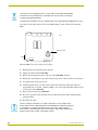
1
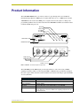
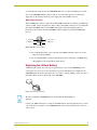
instruction manual
AXB-MIDI
MIDI Interface
AXlink Bus Controllers
AMX Limited Warranty and Disclaimer
AMX Corporation warrants its products to be free of defects in material and workmanship under normal use for
three (3) years from the date of purchase from AMX Corporation, with the following exceptions:
•
Electroluminescent and LCD Control Panels are warranted for three (3) years, except for the display and touch
overlay components that are warranted for a period of one (1) year.
•
Disk drive mechanisms, pan/tilt heads, power supplies, MX Series products, and KC Series products are
warranted for a period of one (1) year.
•
Unless otherwise specified, OEM and custom products are warranted for a period of one (1) year.
•
Software is warranted for a period of ninety (90) days.
•
Batteries and incandescent lamps are not covered under the warranty.
This warranty extends only to products purchased directly from AMX Corporation or an Authorized AMX Dealer.
AMX Corporation is not liable for any damages caused by its products or for the failure of its products to perform.
This includes any lost profits, lost savings, incidental damages, or consequential damages. AMX Corporation is not
liable for any claim made by a third party or by an AMX Dealer for a third party.
This limitation of liability applies whether damages are sought, or a claim is made, under this warranty or as a tort
claim (including negligence and strict product liability), a contract claim, or any other claim. This limitation of
liability cannot be waived or amended by any person. This limitation of liability will be effective even if AMX
Corporation or an authorized representative of AMX Corporation has been advised of the possibility of any such
damages. This limitation of liability, however, will not apply to claims for personal injury.
Some states do not allow a limitation of how long an implied warranty last. Some states do not allow the limitation or
exclusion of incidental or consequential damages for consumer products. In such states, the limitation or exclusion of
the Limited Warranty may not apply. This Limited Warranty gives the owner specific legal rights. The owner may
also have other rights that vary from state to state. The owner is advised to consult applicable state laws for full
determination of rights.
EXCEPT AS EXPRESSLY SET FORTH IN THIS WARRANTY, AMX CORPORATION MAKES NO
OTHER WARRANTIES, EXPRESSED OR IMPLIED, INCLUDING ANY IMPLIED WARRANTIES OF
MERCHANTABILITY OR FITNESS FOR A PARTICULAR PURPOSE. AMX CORPORATION
EXPRESSLY DISCLAIMS ALL WARRANTIES NOT STATED IN THIS LIMITED WARRANTY. ANY
IMPLIED WARRANTIES THAT MAY BE IMPOSED BY LAW ARE LIMITED TO THE TERMS OF THIS
LIMITED WARRANTY.
Table of Contents
Table of Contents
Product Information .................................................................................................1
Installation .................................................................................................................3
Setting the DEVICE DIP Switch ........................................................................................ 3
Preparing Captive Wires for AXlink.......................................................................................... 3
Wiring the AXB-MIDI ......................................................................................................... 3
AXlink data and power connections ......................................................................................... 3
AXlink Wiring Guidelines.......................................................................................................... 4
Wiring AXlink with Optional 12 VDC power supply .................................................................. 4
MIDI cable connectors ............................................................................................................. 5
Replacing the Lithium Battery ........................................................................................... 5
Programming ............................................................................................................7
Send Commands............................................................................................................... 7
IN A and IN B MIDI Signal Routing ................................................................................... 8
MIDI Programming ............................................................................................................ 9
Programming examples ........................................................................................................... 9
Summary of MIDI Messages ........................................................................................... 11
AXB-MIDI MIDI Interface
i
Table of Contents
ii
AXB-MIDI MIDI Interface
Product Information
Product Information
The AXB-MIDI MIDI Interface is an Axcess device for pass-through and control of Musical
Instrument Digital Interface (MIDI) protocol signals. This unit can act as a MIDI matrix switcher.
AXB-MIDI decodes and encodes MIDI protocol signals and routes the signals according to the
programming within an Axcess Central Controller. The AXB-MIDI communicates with the Central
Controller AXlink data protocols..
OUT LED
THRU LED
IN - MIDI B
IN - MIDI A
AXlink Status LED
IN
A
DEVICE
AXlink
IN
B
THRU
Front
OUT
ON
DEVICE DIP Switch
AXP
OUT
PWR
THRU
AXM
IN B
GND
IN A
Rear
AXlink
MIDI A INPUT
MIDI B INPUT
MIDI THRU
MIDI OUT
AXlink connector
FIG. 1 AXB-MIDI - front and rear panel components
The AXB-MIDI provides MIDI signal pass-through and device control. Processing of MIDI
signaling is instantly visible via four front panel LEDs. A lithium battery provides data backup in
the event of power failure. The unit can be mounted in an electronic rack using an optional AC-RK
Accessory Rack Kit.
AXB-MIDI Specifications
Dimensions (HWD)
1.51" x 5.55" x 5.45" (3.84 cm x 14.10 cm x 13.84 cm)
Enclosure
Metal with black matte finish
Power consumption
75 mA @ 12VDC
DIP Switch
8-position DIP switch sets the AXlink address for the AXB-MIDI.
Connectors
• Four 5-pin DIN MIDI connectors (IN A, IN B, THRU and OUT).
• 4-pin captive wire connector for AXlink control signaling and power from the
Central Controller.
AXB-MIDI MIDI Interface
1
Product Information
AXB-MIDI Specifications (Cont.)
Input buffer
• 3,072 bytes
Output buffer (AXlink)
• 6,143 bytes
Max. Length of
SEND_STRING to device
• 64
Max. Length of data packets
from device
• 64
LED Indicators
• AXlink Status LED (green): Lights to indicate that the AXB-MIDI is
operational and interfacing with the Central Controller (when blinking once
per second).
• IN A LED (red): Lights to indicate that there is MIDI data present on the IN A
connector.
• IN B LED (red): Lights to indicate that there is MIDI data present on the IN B
connector.
• THRU LED (red): Lights to indicate MIDI IN A/B signal passing through
without any changes.
• OUT LED (red): Lights to indicate MIDI data is being transmitted out the OUT
connector (after the AXB-MIDI receives AXlink control commands or MIDI
signals from the Central Controller).
Weight
1 lb. 0.5 oz. (488 grams)
Mounting options
Flat surface or Rack mount
Optional Accessories
• PS2.8, 12 VDC, 2.8 A Power Supply
• Five-pin DIN MIDI cable
• AC-ARK Accessory Rack Kit
2
AXB-MIDI MIDI Interface
Installation
Installation
Setting the DEVICE DIP Switch
The 8-position DIP switch (see FIG. 1) sets the AXlink device number for the AXB-MIDI. The
device number must match the number assigned in the Axcess software program.
The Device DIP switch example shown in FIG. 2 is set to the factory default setting of 90
(2 + 8 + 16 + 64 = 90).
1 2 3 4 5 6 7 8
FIG. 2 DEVICE DIP Switch, shown set to default address setting (90)
The AXlink device number range is 1-255, and is set according to the Device DIP switch positions
and their values shown in the following table:
Device DIP Switch Settings
Position
1
2
3
4
5
6
7
8
Value
1
2
4
8
16
32
64
128
Preparing Captive Wires for AXlink
Use a wire stripper and flat-blade screwdriver to prepare and connect the AXlink captive wires:
1. Strip 0.25 inch off the wire insulation for all four wires.
2. Insert the exposed section of each wire into the appropriate opening on the captive wire
connector according to the wiring diagrams shown in the Installation section of this manual.
3. Using a flat-blade screwdriver, turn the screws clockwise to secure the wire in the connector.
Wiring the AXB-MIDI
The AXB-MIDI requires 12.5 VDC to operate properly. The power can be supplied by the Central
Controller's power supply and AXlink cable or with an optional 12 VDC power supply. The
maximum wiring distance between the Central Controller and AXB-MIDI is determined by power
consumption, supplied voltage, and the wire gauge used for the cable.
AXlink data and power connections
Connect the Central Controller's AXlink connector to the AXlink connector on the rear panel of the
AXB-MIDI (see FIG. 1) for data and 12 VDC power, as shown in FIG. 3.
AXB-MIDI MIDI Interface
3
Installation
PWR +
PWR +
AXP/TX
AXP/TX
AXM/RX
AXM/RX
GND -
GND AXB-MIDI
Central Controller
FIG. 3 AXlink wiring
If using power from AXlink, disconnect the wiring from the Central Controller before
wiring the AXB-MIDI.
AXlink Wiring Guidelines
The following table lists wire sizes and maximum lengths allowable between the AXB-MIDI and
the Central Controller power supply. The maximum wiring lengths are based on 13.5 VDC @ 100
mA available at the Central Controller's power supply output cable end.
AXlink Wiring Guidelines
Wire Size Max Wiring Length
18 AWG
1,173.71 ft (357.74 m)
20 AWG
742.57 ft (226.34 m)
22 AWG
462.96 ft (141.11 m)
24 AWG
291.83 ft (88.95 m)
If the AXB-MIDI is installed farther away from the Central Controller than recommended, connect
an optional 12 VDC power supply to the AXlink connector on the AXB-MIDI rear panel (see the
Wiring AXlink with Optional 12 VDC power supply section on page 4).
Wiring AXlink with Optional 12 VDC power supply
Connect the Central Controller's AXlink connector to the AXlink connector on the rear panel of the
AXB-MIDI, as shown in FIG. 4.
PWR (+)
Local +12 VDC power supply
(coming from the PSN power supply)
GND (-)
PWR +
PWR +
AXP/TX
AXP/TX
AXM/RX
AXM/RX
GND -
GND AXB-MIDI
Central Controller
FIG. 4 Wiring AXlink with Optional 12 VDC power supply
Use an external 12 VDC power supply when the distance between the Central Controller and
AXB-MIDI exceeds the limits described in Figure 9 or the power supply current capacity cannot
4
AXB-MIDI MIDI Interface
Installation
accommodate the 75 mA draw of the AXB-MIDI. Make sure to connect the GND and +12 VDC
wire on the AXB-MIDI AXlink connector end. Do not connect the optional +12 VDC power
supply wire to the Central Controller's power supply side of the AXlink connector.
MIDI cable connectors
The four MIDI jacks on the rear panel (IN A, IN B, THRU and OUT) are identical 5-pin DIN type
connectors. FIG. 5 shows the pinout for wiring cables to these DIN connectors. It is recommended
that off the shelf MIDI cables be used. MIDI cable lengths will be determined by physical
placement of the Central Controller, AXB-MIDI, and the equipment providing the MIDI input
protocol.
1 - (not used)
3 - (not used)
5 - Signal ( -)
4 - Signal (+)
2 - shielded ground
FIG. 5 MIDI DIN connector pinout
!
Pin 2 (shielded ground) is only connected on the THRU and OUT connectors. It is not
connected on IN A and IN B.
!
It is recommended that to maintain signal integrity when connecting to any MIDI device,
cable lengths be no more than 20 feet (6.01 meters).
Replacing the Lithium Battery
A lithium battery (Figure 15), with a life of approximately 5 years, in the AXB-MIDI protects
stored presets if a power loss occurs. The battery is not used when DC power is supplied to the
AXB-MIDI. Write down the replacement date on a sticker or label by adding 5 years to the date of
installation. Then attach it to the bottom of the AXB-MIDI.
FIG. 6 Lithium battery and socket
All control commands in AXB-MIDI memory are lost when the lithium battery is
replaced.
Contact your AMX dealer before you replace the lithium battery and verify that they have a current
copy of the Axcess program for your AXB-MIDI. This will avoid any inadvertent loss of data or a
service outage.
AXB-MIDI MIDI Interface
5
Installation
Static electricity can damage electronic circuitry. Before removing the lithium battery
from the enclosure, discharge any accumulated static electricity from your body by
touching a grounded metal object.
You will need a flat-blade tool (non-conducting) that can be slipped under the lithium battery to pry
it up and out of the socket. The location of the Lithium battery on the circuit board is shown in
FIG. 7.
rear
Battery/socket
front
FIG. 7 AXB-MIDI circuit card, showing location of battery
1. Discharge the static electricity from your body.
2. Unplug all cables from the AXB-MIDI.
3. Remove the five pan-head screws on the top of the AXB-MIDI enclosure.
4. Pull the two enclosure halves apart and set the bottom portion of the enclosure on a flat surface.
5. Locate the battery on the circuit card.
6. Carefully pry the battery out of its socket and insert the new battery. Write down the next
replacement date on a sticker or label by adding 5 years to the replacement date. Then attach it
to the bottom of the AXB-MIDI.
7. Plug all cables back into the AXB-MIDI.
8. Place the top portion of the enclosure back onto the bottom portion. Then, refasten the five
pan-head screws.
9. Reconnect the cables.
There is a danger of explosion if you replace the battery incorrectly. Replace the
battery with the same or equivalent type recommended by the manufacturer. Dispose
of used battery according to the manufacturer's instructions. Never recharge,
disassemble, or heat the battery above 212°F (100°C). Never solder directly to the
battery or expose the contents of the battery to water.
6
AXB-MIDI MIDI Interface
Programming
Programming
Send Commands
Send_Commands control AXB-MIDI signal routing by the Central Controller. The AXB-MIDI
supports the Send_Commands described below.
AXB-MIDI Send_Commands
Command
Description
INA
Syntax:
Configure the destination for
'INA-<value>'
the incoming data on IN A
Parameter:
(see the IN A and IN B Signal
<value> = 0 to 7
Routing table on page 8).
Example:
SEND_COMMAND <device>,'INA-5'
Routes incoming IN A data to THRU output and to the Central Controller.
INB
Configure the destination for
the incoming data on MIDI
IN B.(see the IN A and IN B
Signal Routing table on
page 8).
Syntax:
'INB-<value>'
Parameter:
<value> = 0 to 7
Example:
SEND_COMMAND <device>,'INB-7'
Routes incoming IN B data to THRU output, OUT output, and transmit data to
the Central Controller.
RXACLR
Clear characters waiting in
the IN A receive buffer (to be
sent to the Central
Controller, MIDI THRU, or
MIDI OUT).
RXBCLR
Clear characters waiting in
the IN B receive buffer (to be
sent to the Central
Controller, MIDI THRU, or
MIDI OUT).
RXCLR
Syntax:
'RXACLR'
Example:
SEND_COMMAND <device>,'RXACLR'
Clears the IN A receive buffer of all contents.
Syntax:
'RXBCLR'
Example:
SEND_COMMAND <device>,'RXBCLR'
Clears the receive buffer contents for IN B.
Syntax:
Clear all characters waiting in
'RXCLR'
both receive buffers (to be
Example:
sent to the Central
SEND_COMMAND <device>,'RXCLR'
Controller, MIDI THRU, or
MIDI OUT).
Clears the receive buffers or all content for IN A and IN B.
RXON
Syntax:
Enable the ABX-MIDI to send
'RXON'
received characters to the
This command is automatically sent by the Central Controller when a
Central Controller.
CREATE_BUFFER program instruction is executed.
Example:
SEND_COMMAND <device>,'RXON'
Sends received characters from IN A and IN B to the Central Controller.
AXB-MIDI MIDI Interface
7
Programming
AXB-MIDI Send_Commands (Cont.)
Command
Description
RXOFF
Syntax:
The AXB-MIDI will not pass
on received characters to the
Central Controller. This is the
default.
'RXOFF'
Example:
SEND_COMMAND <device>,'RXOFF'
Turns IN A and IN B transmit to the Central Controller off.
TXCLR
Syntax:
Clear all characters waiting in
'TXCLR'
both transmit buffers (MIDI
Example:
THRU and MIDI OUT).
SEND_COMMAND <device>,'TXCLR'
Clears THRU and OUT transmit buffers.
TXTHRUCLR
Syntax:
Clear characters waiting in
the MIDI THRU transmit
buffer.
'TXTHRUCLR'
Clear characters waiting in the MIDI THRU transmit buffer.
Example:
SEND_COMMAND <device>,'TXTHRUCLR'
Clears THRU transmit buffer.
TXOUTCLR
Syntax:
'TXOUTCLR'
Clears characters waiting in the MIDI OUT transmit buffer.
Example:
SEND_COMMAND <device>,'TXOUTCLR'
Clears OUT transmit buffer of all contents.
IN A and IN B MIDI Signal Routing
The following table shows all routing value possibilities for IN A and IN B incoming MIDI signals
in relation to the AXB-MIDI rear panel connectors. The value determines where the IN A and IN B
MIDI signals will be routed.
IN A and IN B Signal Routing
Value
THRU
OUT
AXlink
0
1
X
2
3
X
X
X
4
5
X
X
6
7
X
X
X
X
X
X
The power-up default value is 3.
Inputs are controlled as Channels 1 through 8.
8
AXB-MIDI MIDI Interface
Programming
MIDI Programming
Most MIDI command strings consist of a status byte followed by one or two data bytes. The most
notable exception to this is the System Exclusive which starts with a status byte of $F0, has 4 or
more data bytes, then ends with a status byte of $F7. Status bytes are always $80 or greater. Status
bytes are always denoted in hexadecimal. Data bytes are always less than $80 (128 in decimal).
Data bytes may be denoted in either decimal or hexadecimal.
Program change, Control change, and Note On/Off are the most often used of the MIDI "Channel
Voice" commands. Since they are standard MIDI commands they are almost never explained in
manufacturers programming manuals. Program change (Preset), Control change, Note On/Off, and
System Exclusive.
Programming examples
The following section provides some programming examples:
SEND_STRING MIDI,"$C0 + (MIDI_CHANNEL - 1), PROGRAM - 1"
Specific example, to recall preset 128 on MIDI ch 1:
MIDI_CHANNEL = 1
1 - 1 = 0
$C0 + 0 = $C0,
PROGRAM = 128
128 - 1 = 127, thus the send string,
SEND_STRING MIDI,"$C0,127"
The Program change is denoted by status byte $C0 (for MIDI channel 1) through status byte $CF
(for MIDI channel 16), followed by one data byte.
PRGM EX. 1
SEND_STRING MIDI,"$90 + (MIDI_CHANNEL - 1), Note, Velocity"
SEND_STRING MIDI,"$80 + (MIDI_CHANNEL - 1), Note, Velocity"
(* Note On *)
(* Note Off *)
Note that On is denoted by status byte $90 (for MIDI channel 1) through status byte $9F (for MIDI
channel 16), Note that Off is denoted by status byte $80 (for MIDI channel 1) through status byte $8F (for
MIDI channel 16).
PRGM EX. 2
SEND_STRING MIDI,"$80 + (MIDI_CHANNEL - 1), Note, 0"
(* Note Off *)
Most modern controllers send a $90 note on with velocity 0 for note off (We'll save the reason why for
MIDI programming 102).
PRGM EX. 3
AXB-MIDI MIDI Interface
9
Programming
SEND_STRING MIDI,"$B0 + (MIDI_CHANNEL - 1), CONTROLLER, VALUE"
Specific example set volume to 50% on MIDI ch 5:
MIDI_CHANNEL = 5
5 - 1 = 4
$B0 + 4 = $B4,
The standard MIDI Volume controller is 7,
127 * 50% = 64 (approximately), thus the send string,
SEND_STRING MIDI,"$B4, 7, 64"
Selected MIDI controller numbers:
BANK SELECT MSB
VOLUME
PAN
EXPRESSION
GENERAL PURPOSE
GENERAL PURPOSE
GENERAL PURPOSE
GENERAL PURPOSE
BANK SELECT LSB
HOLD
CONTROLLER
CONTROLLER
CONTROLLER
CONTROLLER
#
#
#
#
REVERB SEND
EFFECTS 2 DEPTH
CHORUS SEND
EFFECTS 4 DEPTH
EFFECTS 5 DEPTH
ALL SOUND OFF
RESET ALL CONTROLLERS
1
2
3
4
=
=
=
=
=
=
=
=
=
=
64
=
=
=
=
=
=
=
0
7
10
11 (* A SECOND VOLUME CONTROL *)
16
17
18
19
32
(* 2nd data byte of 63 or less = OFF,
64 or greater = ON *)
91
92
93
94
95
120 (* 2nd data byte is always "0" *)
121 (* 2nd data byte is always "0" *)
The Control change is denoted by status byte $B0 (for MIDI channel 1) through status byte $BF (for MIDI
channel 16), followed by two data bytes.
PRGM EX. 4
MIDI_CHANNEL = 6
6 - 1 = 5
$90 + 5 = $95
Note = 60
Velocity = 96, thus the send string,
SEND_STRING MIDI,"$95,60,96"
To turn the same note off:
SEND_STRING MIDI,"$95,60,0"
Specific example, Middle C (Note #60) on, on MIDI ch 6. If you're not sure what velocity to use try something between 64 (half) and 127(full), how about 96?
PRGM EX. 5
10
AXB-MIDI MIDI Interface
Programming
(* MMC STOP *)
SEND_STRING MIDI,"$F0,$7F,$7F,$06,$01,$F7"
(* MMC PLAY *)
SEND_STRING MIDI,"$F0,$7F,$7F,$06,$02,$F7"
(* MMC DEFERRED PLAY *)
SEND_STRING MIDI,"$F0,$7F,$7F,$06,$03,$F7"
(* MMC FAST FWD *)
SEND_STRING MIDI,"$F0,$7F,$7F,$06,$04,$F7"
(* MMC REW *)
SEND_STRING MIDI,"$F0,$7F,$7F,$06,$05,$F7"
(* MMC RECORD STROBE *)
SEND_STRING MIDI,"$F0,$7F,$7F,$06,$06,$F7"
(* MMC RECORD EXIT *)
SEND_STRING MIDI,"$F0,$7F,$7F,$06,$07,$F7"
(* MMC RECORD PAUSE *)
SEND_STRING MIDI,"$F0,$7F,$7F,$06,$08,$F7"
(* MMC PAUSE *)
SEND_STRING MIDI,"$F0,$7F,$7F,$06,$09,$F7"
Most System Exclusives start with $F0, then a three byte system exclusive address, then more data bytes
as determined by the manufacturer, then an end byte of $F7. Unlike the channel voice messages which
are part of the MIDI standard, the system exclusives are usually well explained in the manufacturers
programming manual.
One exception to this is MMC, or MIDI Machine Control. It's part of the MIDI standard. These MMC
commands were captured from a Roland FC-200 MIDI Foot Controller. The address of "$F7,$F7,$06"
means "Universal Realtime Message, Broadcast, MMC". Then there is a single data byte followed by the
end byte $F7.
PRGM EX. 6
Summary of MIDI Messages
The following information refers to MIDI messages and Control Change Messages. The following
table lists and describes Channel Voice messages ([nnnn = 0-15 (MIDI Channel Number 1-16)]):
Channel Voice Messages
Status (D7---D0)
1000nnnn
Data Bytes (D7---D0)
Description
• 0kkkkkkk
• Note Off event.
• 0vvvvvvv
• This message is sent when a note is released (ended).
• (kkkkkkk) is the key (note) number. (vvvvvvv) is the velocity.
1001nnnn
• 0kkkkkkk
• Note On event.
• 0vvvvvvv
• This message is sent when a note is depressed (start).
• (kkkkkkk) is the key (note) number. (vvvvvvv) is the velocity.
1010nnnn
• 0kkkkkkk
• 0vvvvvvv
• Polyphonic Key Pressure (Aftertouch). This message is most
often sent by pressing down on the key after it "bottoms out".
• (kkkkkkk) is the key (note) number. (vvvvvvv) is the velocity.
1011nnnn
• 0ccccccc
• Control Change.
• 0vvvvvvv
• This message is sent when a controller value changes.
Controllers include devices such as pedals and levers.
• Controller numbers 120-127 are reserved as "Channel Mode
Messages" (below).
• (ccccccc) is the controller number. (vvvvvvv) is the new value
(0-119).
AXB-MIDI MIDI Interface
11
Programming
Channel Voice Messages (Cont.)
Status (D7---D0)
Data Bytes (D7---D0)
Description
1100nnnn
• 0ppppppp
• Program Change.
• This message sent when the patch number changes.
• (ppppppp) is the new program number.
1101nnnn
• 0vvvvvvv
• Channel Pressure (After-touch).
• This message is most often sent by pressing down on the
key after it "bottoms out". This message is different from
polyphonic after-touch. Use this message to send the single
greatest pressure value (of all the current depressed keys).
• (vvvvvvv) is the pressure value.
1110nnnn
• 0lllllll
• Pitch Wheel Change.
• 0mmmmmmm
• This message is sent to indicate a change in the pitch wheel.
The pitch wheel is measured by a fourteen bit value. Center
(no pitch change) is 2000H. Sensitivity is a function of the
transmitter.
• (llllll) are the least significant 7 bits. (mmmmmm) are the
most significant 7 bits.
The following table lists and describes System Common messages:
System Common Messages
Status (D7---D0)
11110000
Data Bytes (D7---D0)
Description
• 0iiiiiii
• System Exclusive.
• 0ddddddd
• This message makes up for all that MIDI doesn't support.
(iiiiiii) is usually a seven-bit Manufacturer's I.D. code. If the
synthesizer recognizes the I.D. code as its own, it will listen
to the rest of the message (ddddddd). Otherwise, the
message will be ignored. System Exclusive is used to send
bulk dumps such as patch parameters and other non-spec
data. (Note: Real-Time messages ONLY may be interleaved
with a System Exclusive.)
..
..
• 0ddddddd
• 11110111
• This message also is used for extensions called Universal
Exclusive Messages.
11110001
11110010
11110011
• Undefined. (Reserved).
• 0lllllll
• Song Position Pointer.
• 0mmmmmmm
• This is an internal 14 bit register that holds the number of
MIDI beats (1 beat=six MIDI clocks) since the start of the
song. l is the LSB, m the MSB.
• 0sssssss
• Song Select.
• The Song Select specifies which sequence or song is to be
played.
11110100
• Undefined. (Reserved).
11110101
• Undefined. (Reserved).
11110110
• Tune Request.
• Upon receiving a Tune Request, all analog synthesizers
should tune their oscillators.
11110111
• End of Exclusive.
• Used to terminate a System Exclusive dump (see above).
12
AXB-MIDI MIDI Interface
Programming
The following table lists and describes System Real-Time Messages:
System Real-Time Messages
Status (D7---D0)
Data Bytes (D7---D0)
11111000
Description
• Timing Clock.
• Sent 24 times per quarter note when synchronization is
required.
11111001
• Undefined. (Reserved).
11111010
• Start.
• Start the current sequence playing. (This message will be
followed with Timing Clocks).
11111011
• Continue.
• Continue at the point the sequence was Stopped.
11111100
• Stop.
11111101
• Undefined. (Reserved).
11111110
• Active Sensing.
• Stop the current sequence.
• Use of this message is optional. When initially sent, the
receiver will expect to receive another Active Sensing
message each 300ms (max), or it will be assume that the
connection has been terminated.
• At termination, the receiver will turn Off all voices and return
to normal (non-active sensing) operation.
11111111
• Reset.
• Reset all receivers in the system to power-up status. This
should be used sparingly, preferably under manual control.
• In particular, it should not be sent on power-up.
The following table lists and describes Channel Mode messages:
Channel Mode Messages
Status (D7---D0)
Data Bytes (D7---D0)
Description
1011nnnn
• 0ccccccc
• Channel Mode Messages.
• 0vvvvvvv
• This the same code as the Control Change (above), but
implements Mode control and special message by using
reserved controller numbers 120-127.
• All Sound Off.
When All Sound Off is received all oscillators will turn
Off, and their volume envelopes are set to zero as soon
as possible.
c = 120, v = 0: All Sound Off
• Reset All Controllers.
When Reset All Controllers is received, all controller
values are reset to their default values.
c = 121, v = x: Value must only be zero unless
otherwise allowed in a specific Recommended Practice.
• Local Control.
When Local Control is Off, all devices on a given
channel will respond only to data received over MIDI.
Played data, etc. will be ignored. Local Control On
restores the functions of the normal controllers.
c = 122, v = 0: Local Control Off
c = 122, v = 127: Local Control On
AXB-MIDI MIDI Interface
13
Programming
Channel Mode Messages (Cont.)
Status (D7---D0)
1011nnnn (Cont.)
Data Bytes (D7---D0)
Description
• All Notes Off.
When an All Notes Off is received, all oscillators will
turn Off.
c = 123, v = 0: All Notes Off
c = 124, v = 0: Omni Mode Off
c = 125, v = 0: Omni Mode On
c = 126, v = M: Mono Mode On (Poly Off) where M is
the number of channels (Omni Off) or 0 (Omni On)
c = 127, v = 0: Poly Mode On (Mono Off)
• (Note: These four messages also cause All Notes Off).
14
AXB-MIDI MIDI Interface
Programming
AXB-MIDI MIDI Interface
15
brussels • dallas • los angeles • mexico city • philadelphia • shanghai • singapore • tampa • toronto* • york
3000 research drive, richardson, TX 75082 USA • 469.624.8000 • 800.222.0193 • fax 469.624.7153 • technical support 800.932.6993
032-004-1335 6/02 ©2002 AMX Corporation. All rights reserved. AMX, the AMX logo, the building icon, the home icon, and the light bulb icon are all trademarks of AMX Corporation.
AMX reserves the right to alter specifications without notice at any time. *In Canada doing business as Panja Inc.
AMX reserves the right to alter specifications without notice at any time.