1
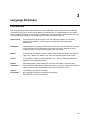
Programming Guide
AC Power Solutions
Agilent Models 6811B, 6812B, 6813B
6814B, 6834B, and 6843A
Agilent Part No. 5962-0889
Microfiche No 6962-0890
Printed in U.S.A.
December, 1998
Update April 2000
Safety Summary
The beginning of the ac source User’s Guide has a Safety Summary page. Be sure you are familiar with
the information on this page before programming the ac source from a controller.
WARNING:
ENERGY HAZARD. Ac sources can supply 425 V peak at their output. DEATH on
contact may result if the output terminals or circuits connected to the output are
touched when power is applied.
Printing History
The edition and current revision of this manual are indicated below. Reprints of this manual containing
minor corrections and updates may have the same printing date. Revised editions are identified by a new
printing date. A revised edition incorporates all new or corrected material since the previous printing date.
Changes to the manual occurring between revisions are covered by change sheets shipped with the
manual.
This document contains proprietary information protected by copyright. All rights are reserved. No part of
this document may be photocopied, reproduced, or translated into another language without the prior
consent of Agilent Technologies. The information contained in this document is subject to change without
notice.
Copyright 1996-1998, 2000 Agilent Technologies, Inc.
2
Edition 1 __________August, 1996
Edition 2 __________March, 1997
Edition 3 __________December, 1998
Update __________April, 2000
Table of Contents
Safety Summary
Printing History
Table of Contents
1 - GENERAL INFORMATION
About this Guide
Earlier AC Source Models
Documentation Summary
External References
SCPI References
GPIB References
Agilent VXIplug&play Power Products Instrument Drivers
Supported Applications
System Requirements
Downloading and Installing the Driver
Accessing Online Help
2 - INTRODUCTION TO PROGRAMMING
GPIB Capabilities of the AC Source
GPIB Address
RS-232 Capabilities of the AC Source
RS-232 Data Format
Baud Rate
RS-232 Programming Example
RS-232 Troubleshooting
Introduction to SCPI
Conventions Used in This Guide
Types of SCPI Commands
Types of SCPI Messages
The SCPI Command Tree
The Root Level
Active Header Path
The Effect of Optional Headers
Moving Among Subsystems
Including Common Commands
Using Queries
Coupled Commands
Structure of a SCPI Message
The Message Unit
Combining Message Units
Headers
Query Indicator
Message Unit Separator
Root Specifier
Message Terminator
SCPI Data Formats
Numerical Data Formats
Suffixes and Multipliers
Character Data
2
2
3
11
11
11
11
12
12
12
12
12
13
13
13
15
15
15
15
15
15
16
16
17
17
17
17
18
18
18
19
19
20
20
20
20
20
21
21
22
22
22
22
23
23
23
23
3
System Considerations
Assigning the GPIB Address in Programs
Types of DOS Drivers
Error Handling
Agilent BASIC Controllers
3 - LANGUAGE DICTIONARY
Introduction
Subsystem Commands
Calibration Subsystem Commands
Subsystem Syntax
CALibrate:CURRent:AC
CALibrate:CURRent:MEASure
CALibrate:DATA
CALibrate:IMPedance
CALibrate:LEVel
CALibrate:PASSword
CALibrate:PWM:FREQuency
CALibrate:PWM:RAMP
CALibrate:SAVE
CALibrate:STATe
CALibrate:VOLTage:AC
CALibrate:VOLTage:DC
CALibrate:VOLTage:OFFSet
CALibrate:VOLTage:PROTection
CALibrate:VOLTage:RTIMe
Display Subsystem Commands
Subsystem Syntax
DISPlay
DISPlay:MODE
DISPlay:TEXT
Instrument Subsystem
Subsystem Syntax
INSTrument:COUPle
INSTrument:NSELect INSTrument:SELect
Measurement Subsystem (Arrays)
Subsystem Syntax
MEASure:ARRay:CURRent? FETCh:ARRay:CURRent?
MEASure:ARRay:CURRent:HARMonic? FETCh:ARRay:CURRent:HARMonic?
MEASure:ARRay:CURRent:HARMonic:PHASe? FETCh:ARRay:CURRent:HARMonic:PHASe?
MEASure:ARRay:CURRent:NEUTral? FETCh:ARRay:CURRent:NEUTral?
MEASure:ARRay:CURRent:NEUTral:HARMonic? FETCh:ARRay:CURRent:NEUTral:HARMonic?
MEASure:ARRay:CURRent:NEUTral:HARMonic:PHASe?
FETCh:ARRay:CURRent:NEUTral:HARMonic:PHASe?
MEASure:ARRay:VOLTage? FETCh:ARRay:VOLTage?
MEASure:ARRay:VOLTage:HARMonic? FETCh:ARRay:VOLTage:HARMonic?
MEASure:ARRay:VOLTage:HARMonic:PHASe? FETCh:ARRay:VOLTage:HARMonic:PHASe?
Measurement Subsystem (Current)
Subsystem Syntax
MEASure:CURRent? FETCh:CURRent?
MEASure:CURRent:AC? FETCh:CURRent:AC?
MEASure:CURRent:ACDC? FETCh:CURRent:ACDC?
MEASure:CURRent:AMPLitude:MAXimum? FETCh:CURRent:AMPLitude:MAXimum?
MEASure:CURRent:CREStfactor? FETCh:CURRent:CREStfactor?
4
24
24
24
25
25
27
27
28
29
29
29
30
30
30
30
31
31
31
31
32
32
32
33
33
33
34
34
34
34
34
35
35
35
36
37
37
37
38
38
39
39
40
40
41
41
42
42
42
43
43
43
44
MEASure:CURRent:HARMonic? FETCh:CURRent:HARMonic?
MEASure:CURRent:HARMonic:PHASe? FETCh:CURRent:HARMonic:PHASe?
MEASure:CURRent:HARMonic:THD? FETCh:CURRent:HARMonic:THD?
MEASure:CURRent:NEUTral? FETCh:CURRent:NEUTral?
MEASure:CURRent:NEUTral:AC? FETCh:CURRent:NEUTral:AC?
MEASure:CURRent:NEUTral:ACDC? FETCh:CURRent:NEUTral:ACDC?
MEASure:CURRent:NEUTral:HARMonic? FETCh:CURRent:NEUTral:HARMonic?
MEASure:CURRent:NEUTral:HARMonic:PHASe? FETCh:CURRent:NEUTral:HARMonic:PHASe?
Measurement Subsystem (Frequency)
Subsystem Syntax
MEASure:FREQuency? FETCh:FREQuency?
Measurement Subsystem (Power)
Subsystem Syntax
MEASure:POWer? FETCh:POWer?
MEASure:POWer:AC? FETCh:POWer:AC?
MEASure:POWer:AC:APParent? FETCh:POWer:AC:APParent?
MEASure:POWer:AC:REACtive? FETCh:POWer:AC:REACtive?
MEASure:POWer:AC:PFACtor? FETCh:POWer:AC:PFACtor?
MEASure:POWer:AC:TOTal? FETCh:POWer:AC:TOTal?
Measurement Subsystem (Voltage)
Subsystem Syntax
MEASure:VOLTage? FETCh:VOLTage?
MEASure:VOLTage:AC? FETCh:VOLTage:AC?
MEASure:VOLTage:ACDC? FETCh:VOLTage:ACDC?
MEASure:VOLTage:HARMonic? FETCh:VOLTage:HARMonic?
MEASure:VOLTage:HARMonic:PHASe? FETCh:VOLTage:HARMonic:PHASe?
MEASure:VOLTage:HARMonic:THD? FETCh:VOLTage:HARMonic:THD?
Output Subsystem
Subsystem Syntax
OUTPut
OUTPut:COUPling
OUTPut:DFI
OUTPut:DFI:SOURce
OUTPut:IMPedance
OUTPut:IMPedance:REAL
OUTPut:IMPedance:REACtive
OUTPut:PON:STATe
OUTPut:PROTection:CLEar
OUTPut:PROTection:DELay
OUTPut:RI:MODE
OUTPut:TTLTrg
OUTPut:TTLTrg:SOURce
Sense Subsystem
Subsystem Syntax
SENSe:CURRent:ACDC:RANGe
SENSe:SWEep:OFFSet:POINts
SENSe:SWEep:TINTerval
SENSe:WINDow
Source Subsystem (Current)
Subsystem Syntax
CURRent
CURRent:PEAK
CURRent:PEAK:MODE
CURRent:PEAK:TRIGgered
CURRent:PROTection:STATe
44
45
45
45
46
46
46
47
48
48
48
49
49
49
49
50
50
50
51
52
52
52
52
53
53
54
54
55
55
55
56
56
56
57
57
57
58
58
58
59
59
59
60
60
60
61
61
61
62
62
62
63
63
64
64
5
Source Subsystem (Frequency)
Subsystem Syntax
FREQuency
FREQuency:MODE
FREQuency:SLEW
FREQuency:SLEW:MODE
FREQency:SLEW:TRIGgered
FREQuency:TRIGgered
Source Subsystem (Function)
Subsystem Syntax
FUNCtion
FUNCtion:MODE
FUNCtion:TRIGgered
FUNCtion:CSINusoid
Source Subsystem (List)
Subsystem Syntax
LIST:COUNt
LIST:CURRent
LIST:CURRent:POINts?
LIST:DWELl
LIST:DWELl:POINts?
LIST:FREQuency
LIST:FREQuency:POINts?
LIST:FREQuency:SLEW
LIST:FREQuency:SLEW:POINts?
LIST:PHASe
LIST:PHASe:POINts?
LIST:SHAPe
LIST:SHAPe:POINts?
LIST:STEP
LIST:TTLTrg
LIST:TTLTrg:POINts?
LIST:VOLTage
LIST:VOLTage:POINts?
LIST:VOLTage:SLEW
LIST:VOLTage:SLEW:POINts?
LIST:VOLTageOFFSet
LIST:VOLTage:OFFSet:POINts?
LIST:VOLTage:OFFSet:SLEW
LIST:VOLTage:OFFSet:SLEW:POINts?
Source Subsystem (Phase)
PHASe
PHASe:MODE
PHASe:TRIGgered
Source Subsystem (Pulse)
Subsystem Syntax
PULSe:COUNt
PULSe:DCYCle
PULSe:HOLD
PULSe:PERiod
PULSe:WIDTh
6
65
65
65
65
66
66
66
67
68
68
68
69
69
70
71
71
72
72
72
73
73
73
74
74
74
74
75
75
75
76
76
76
77
77
77
78
78
78
79
79
80
80
81
81
82
82
82
82
83
84
84
Source Subsystem (Voltage)
85
Subsystem Syntax
85
VOLTage
86
VOLTage:TRIGgered
86
VOLTage:MODE
87
VOLTage:OFFSet
87
VOLTage:OFFSet:MODE
88
VOLTage:OFFSet:TRIGgered
88
VOLTage:OFFSet:SLEW
89
VOLTage:OFFSet:SLEW:MODE
89
VOLTage:OFFSet:SLEW:TRIGgered
90
VOLTage:PROTection
90
VOLTage:PROTection:STATe
90
VOLTage:RANGe
91
VOLTage:SENSe:DETector VOLTage:ALC:DETector
91
VOLTage:SENSe:SOURce VOLTage:ALC:SOURce
92
VOLTage:SLEW
92
VOLTage:SLEW:MODE
93
VOLTage:SLEW:TRIGgered
93
Status Subsystem
94
Subsystem Syntax
94
STATus:PRESet
94
Bit Configuration of Operation Status Registers
95
STATus:OPERation?
95
STATus:OPERation:CONDition?
95
STATus:OPERation:ENABle
95
STATus:OPERation:NTRansition STATus:OPERation:PTRansition
96
Bit Configuration of Questionable Status Registers
97
STATus:QUEStionable?
97
STATus:QUEStionable:CONDition?
97
STATus:QUEStionable:ENABle
98
STATus:QUEStionable:NTRansition STATus:QUEStionable:PTRansition
98
Bit Configuration of Questionable Instrument Summary Registers
99
STATus:QUEStionable:INSTrument:ISUMmary?
99
STATus:QUEStionable:INSTrument:ISUMmary:CONDition?
100
STATus:QUEStionable:INSTrument:ISUMmary:ENABle
100
STATus:QUEStionable:INSTrument:ISUMmary:NTR STATus:QUEStionable:INSTrument:ISUMmary:PTR101
System Commands
102
Subsystem Syntax
102
SYSTem:CONFigure
102
SYSTem:CONFigure:NOUTputs
103
SYSTem:ERRor?
103
SYSTem:VERSion?
103
SYSTem:LANGuage
104
SYSTem:LOCal
104
SYSTem:REMote
104
SYSTem:RWLock
104
Trace Subsystem
105
Subsystem Syntax
105
TRACe DATA
105
TRACe:CATalog? DATA:CATalog?
106
TRACe:DEFine DATA:DEFine
106
TRACe:DELete DATA:DELete
106
7
Trigger Subsystem
Subsystem Syntax
ABORt
INITiate:SEQuence INITiate:NAME
INITiate:CONTinuous:SEQuence INITiate:CONTinuous:NAME
TRIGger
TRIGger:DELay
TRIGger:SOURce
TRIGger:SEQuence2:SOURce TRIGger:SYNChronize:SOURce
TRIGger:SEQuence2:PHASe TRIGger:SYNCHronize:PHASe
TRIGger:SEQuence3 TRIGger:ACQuire
TRIGger:SEQuence3:SOURce TRIGger:ACQuire:SOURce
TRIGger:SEQuence1:DEFine TRIGger:SEQuence2:DEFine TRIGger:SEQuence3:DEFine
Common Commands
Common Commands Syntax
*CLS
*ESE
Bit Configuration of Standard Event Status Enable Register
*ESR?
*IDN?
*OPC
*OPT?
*PSC
*RCL
*RST
*SAV
*SRE
*STB?
Bit Configuration of Status Byte Register
*TRG
*TST?
*WAI
4 - PROGRAMMING EXAMPLES
Introduction
Programming the Output
Power-on Initialization
Enabling the Output
AC Voltage and Frequency
Voltage and Frequency Slew Rates
Waveform Shapes
Individual Phases (Agilent 6834B only)
Current Limit
DC Output (Agilent 6811B/6812B/6813B only)
Coupled Commands
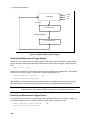
Programming Output Transients
Transient System Model
Step and Pulse Transients
List Transients
Triggering Output Changes
SCPI Triggering Nomenclature
Output Trigger System Model
Initiating the Output Trigger System
Selecting the Output Trigger Source
8
107
107
108
108
109
109
109
110
110
111
111
112
112
113
113
114
114
114
115
115
115
116
116
116
117
118
118
119
119
119
119
120
121
121
121
121
121
122
123
123
124
125
126
127
128
129
130
130
132
132
132
134
134
Specifying a Trigger Delay
Synchronizing Output Changes to a Reference Phase Angle
Generating Output Triggers
Specifying a Dwell Time for Each List Point
Making Measurements
Voltage and Current Measurements
Power Measurements
Harmonic Measurements
Simultaneous Output Phase Measurements (Agilent 6834B only)
Returning Voltage and Current Data From the Data Buffer
Regulatory-Compliant Measurement of Quasi-Stationary Harmonics
Triggering Measurements
SCPI Triggering Nomenclature
Measurement Trigger System Model
Initiating the Measurement Trigger System
Selecting the Measurement Trigger Source
Generating Measurement Triggers
Controlling the Instantaneous Voltage and Current Data Buffers
Programming the Status Registers
Power-On Conditions
Operation Status Group
Questionable Status Group
Questionable Instrument Isummary Status Group
Standard Event Status Group
Status Byte Register
Examples
Programming the Trigger In and Trigger Out BNC Connectors
Trigger In BNC
Trigger Out BNC
Remote Inhibit and Discrete Fault Indicator
Remote Inhibit (RI)
Discrete Fault Indicator (DFI)
SCPI Command Completion
A - SCPI COMMAND TREE
Command Syntax
B - SCPI CONFORMANCE INFORMATION
135
135
136
136
137
137
138
138
138
139
139
139
139
139
140
140
141
141
142
142
142
144
145
146
147
147
148
148
149
149
150
150
150
151
151
155
SCPI Confirmed Commands
Non SCPI Commands
155
156
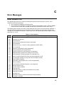
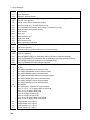
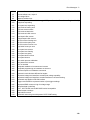
C - ERROR MESSAGES
157
Error Number List
D - ELGAR MODEL 9012 COMPATIBILITY
Elgar Model 9012 Plug-in Programmer Compatibility
Main Board W1 Jumper Option Emulation
Syntax Compatibility
Status Model
Power-on State
Protection
Front Panel Operation
System Keys
157
161
161
161
161
162
162
163
163
163
9
Function Keys
Entry Keys
E9012 Language Command Summary
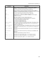
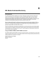
E - IEC MODE COMMAND SUMMARY
Introduction
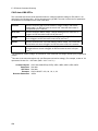
Using the SENSe:CURRent:ACDC:RANGe command
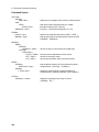
Command Syntax
CALCulate:INTegral:TIME
CALCulate:SMOothing
CALCulate:LIMit:UPPer
FORMat
FORMat:BORDer
MEASure:ARRay:CURRent:HARMonic?
MEASure:ARRay:VOLTage:FLUCtuations:ALL?
MEASure:ARRay:VOLTage:FLUCtuations:FLICker?
MEASure:ARRay:VOLTage:FLUCtuations:PST?
SENSe:CURRent:PREFerence
SENSe:WINDow
SYSTem:CONFigure
INDEX
10
163
164
164
167
167
167
168
169
169
170
171
172
173
174
176
177
178
178
179
181
1
General Information
About this Guide
This manual contains programming information for the Agilent 6811B, 6812B, 6813B, 6814B, 6834B,
6843A AC Power Solutions. These units will be referred to as "ac sources" throughout this manual. You
will find the following information in the rest of this guide:
Chapter 1
Chapter 2
Chapter 3
Chapter 4
Appendix A
Appendix B
Appendix C
Appendix D
Appendix E
Introduction to this guide.
Introduction to SCPI messages structure, syntax, and data formats.
Dictionary of SCPI commands.
Introduction to programming the ac source with SCPI commands.
SCPI command tree.
SCPI conformance information.
Error messages
Elgar Model 9012 plug-in programmer compatibility
IEC mode SCPI commands
Earlier AC Source Models
With the exception of some minor readback specification differences, information in this manual also
applies to the following earlier ac source models:
Information about this
current model
also applies to the following earlier
models:
Agilent 6811B
Agilent 6811A AC Power Source/Analyzer
Agilent 6812B
Agilent 6812A AC Power Source/Analyzer
Agilent 6841A Harmonic/Flicker Test System
in normal mode
Agilent 6813B
Agilent 6813A AC Power Source/Analyzer
Agilent 6842A Harmonic/Flicker Test System
in normal mode
Documentation Summary
The following documents that are related to this Programming Guide have additional helpful information
for using the ac source.
u Quick Start Guide. Information on how to quickly get started using the ac source.
u User’s Guide. Includes specifications and supplemental characteristics, how to use the front
panel, how to connect to the instrument, and calibration procedures.
u Quick Reference Card. Designed as a memory jogger for front panel and GPIB operation.
u Agilent 14761A, 14762A, 14763A User’s Guides are shipped along with the specific software
application and with Agilent 6843A units only.
11
1 - General Information
External References
SCPI References
The following documents will assist you with programming in SCPI:
u Beginner’s Guide to SCPI. Agilent Part No. H2325-90001. Highly recommended for anyone who
has not had previous experience programming with SCPI.
u Tutorial Description of the General Purpose Interface Bus. Agilent Part No. 5952-0156. Highly
recommended for those not familiar with the IEEE 488.1 and 488.2 standards.
To obtain a copy of the above documents, contact your local Agilent Sales and Support Office.
GPIB References
The most important GPIB documents are your controller programming manuals - Agilent BASIC, GPIB
Command Library for MS DOS, etc. Refer to these for all non-SCPI commands (for example: Local
Lockout).
The following are two formal documents concerning the GPIB interface:
u ANSI/IEEE Std. 488.1-1987 IEEE Standard Digital Interface for Programmable Instrumentation.
Defines the technical details of the GPIB interface. While much of the information is beyond the
need of most programmers, it can serve to clarify terms used in this guide and in related
documents.
u ANSI/IEEE Std. 488.2-1987 IEEE Standard Codes, Formats, Protocols, and Common
Commands. Recommended as a reference only if you intend to do fairly sophisticated
programming. Helpful for finding precise definitions of certain types of SCPI message formats,
data types, or common commands.
The above two documents are available from the IEEE (Institute of Electrical and Electronics Engineers),
345 East 47th Street, New York, NY 10017, USA.
Agilent VXIplug&play Power Products Instrument Drivers
Agilent VXIplug&play Power Products instrument drivers for Microsoft Windows 95 and Windows NT are
now available on the Web at http://www.ag.com/go/drivers. These instrument drivers provide a highlevel programming interface to your Agilent Power Products instrument. Agilent VXIplug&play instrument
drivers are an alternative to programming your instrument with SCPI command strings. Because the
instrument driver’s function calls work together on top of the VISA I/O library, a single instrument driver
can be used with multiple application environments.
Supported Applications
ñ
ñ
ñ
ñ
ñ
ñ
12
Agilent VEE
Microsoft Visual BASIC
Microsoft Visual C/C++
Borland C/C++
National Instruments LabVIEW
National Instruments LabWindows/CVI
General Information - 1
System Requirements
The Agilent VXIplug&play Power Products instrument driver complies with the following:
ñ
ñ
ñ
ñ
Microsoft Windows 95
Microsoft Windows NT 4.0
HP VISA revision F.01.02
National Instruments VISA 1.1
Downloading and Installing the Driver
NOTE:
Before installing the Agilent VXIplug&play instrument driver, make sure that you have one
of the supported applications installed and running on your computer.
1. Access Agilent Technologies’ Web site at http://www.ag.com/go/drivers.
2. Select the instrument for which you need the driver.
3. Click on the driver, either Windows 95 or Windows NT, and download the executable file to your
PC.
4. Locate the file that you downloaded from the Web. From the Start menu select Run
<path>:\agxxxx.exe - where <path> is the directory path where the file is located, and agxxxx is
the instrument driver that you downloaded .
5. Follow the directions on the screen to install the software. The default installation selections will
work in most cases. The readme.txt file contains product updates or corrections that are not
documented in the on-line help. If you decide to install this file, use any text editor to open and
read it.
6. To use the VXIplug&play instrument driver, follow the directions in the Agilent VXIplug&play online
help under “Introduction to Programming”.
Accessing Online Help
A comprehensive online programming reference is provided with the driver. It describes how to get
started using the instrument driver with Agilent VEE, LabVIEW, and LabWindows. It includes complete
descriptions of all function calls as well as example programs in C/C++ and Visual BASIC.
ñ
To access the online help when you have chosen the default Vxipnp start folder, click on the Start
button and select Programs | Vxipnp | agxxxx Help (32-bit).
- where agxxxx is the instrument driver.
13
2
Introduction to Programming
GPIB Capabilities of the AC Source
All ac source functions except for setting the GPIB address are programmable over the GPIB. The IEEE
488.2 capabilities of the ac source are listed in the appendix A of the User’s Guide.
GPIB Address
The ac source operates from a GPIB address that is set from the front panel. To set the GPIB address,
press the Address key on the front panel and enter the address using the Entry keys.
RS-232 Capabilities of the AC Source
The ac source provides an RS-232 programming interface, which is activated by commands located under
the front panel Address key. All SCPI and E9012 commands are available through RS-232 programming.
When the RS-232 interface is selected, the GPIB interface is disabled.
The EIA RS-232 Standard defines the interconnections between Data Terminal Equipment (DTE) and
Data Communications Equipment (DCE). The ac source is designed to be a DTE. It can be connected to
another DTE such as a PC COM port through a null modem cable.
NOTE:
The RS-232 settings in your program must match the settings specified in the front panel
Address menu. Press the front panel Address key if you need to change the settings.
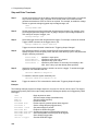
RS-232 Data Format
The RS-232 data is a 11-bit word with one start bit and two stop bits. The number of start and stop bits is
not programmable. The following parity options are selectable using the front panel Address key:
EVEN
ODD
MARK
SPACE
NONE
Seven data bits with even parity
Seven data bits with odd parity
Seven data bits with mark parity (parity is always true)
Seven data bits with space parity (parity is always false)
Eight data bits without parity
Parity options are stored in non-volatile memory.
Baud Rate
The front panel Address key lets you select one of the following baud rates, which is stored in non-volatile
memory: 300
600
1200
2400
4800
9600
15
2 - Introduction to Programming
RS-232 Programming Example
The following program illustrates how to program the ac source using RS-232 to set the output voltage
and frequency and to read back the model number and output voltage. The program was written to run on
any controller using Microsoft QBasic.
NOTE:
The ac source must be configured for RS232 and the same baud rate and parity as the
controller.
‘ Program to write and read via RS232
‘ Configure serial port for:
‘
9600 baud
‘
7 bit data
‘
2 stop bits
‘
Ignore request to send
‘
Ignore carrier detect
‘
Even parity
‘ Needed with Vectra basic, ignored with QBasic
‘
Send line feed
‘
Reserve 1000 character buffer for serial I/O
‘
DECLARE FUNCTION gets$ ()
‘ Function to read string from ac source
CLS
‘ Clears screen
LOCATE 1, 1
‘ Position cursor at top left
‘ Configure Com1 Port
OPEN “com1:9600,e,7,2,rs,cd,pe,lf” FOR RANDOM AS #1 LEN = 1000
PRINT #1, “*RST”
‘ Resets the ac source
PRINT #1, “VOLT 60”
‘ Set voltage to 60 volts
PRINT #1, “FREQ 50”
‘ Set frequency to 50 hertz
PRINT #1, “OUTPUT ON”
‘ Turn on the output
PRINT #1, “*IDN?”
‘ Query the ac source identification string
PRINT gets$
‘ Go to gets$ Function and print data returned
PRINT #1, MEAS”VOLT?”; volt
‘ Query the ac source voltage
Volt = VAL (gets$)
‘ Convert gets$ string to a value
PRINT gets$
‘ Print the value of the voltage
END
‘ End of main program
FUNCTION gets$
C$ = “”
WHILE c$ <> CHR$ (10)
C$ = INPUT$ (1, #1)
Resp$ = resp$ + c$
WEND
gets$ = resp$
END FUNCTION
‘
‘
‘
‘
‘
‘
‘
Get a new line feed terminated string from device #1
Set C$ to null
Set loop to stop at Line Feed
Read 1 bit into file #1
Concatenate bit with previous bits
End of WHILE loop
Assign response to gets$
RS-232 Troubleshooting
If you are having trouble communicating over the RS-232 interface, check the following:
16
♦
The computer and the ac source must be configured for the same baud rate, parity, and number
of data bits. Note that the ac source is configured for 1 start bit and 2 stop bits (these values are
fixed).
♦
The correct interface cables or adaptors must be used, as described under "RS-232 Connector" in
the User’s Guide. Note that even if the cable has the proper connectors for your system, the
internal wiring may be incorrect.
♦
The interface cable must be connected to the correct serial port on your computer (COM1, COM2,
etc.).
Introduction to Programming - 2
Introduction to SCPI
SCPI (Standard Commands for Programmable Instruments) is a programming language for controlling
instrument functions over the GPIB. SCPI is layered on top of the hardware-portion of IEEE 488.2. The
same SCPI commands and parameters control the same functions in different classes of instruments. For
example, you would use the same DISPlay command to control the ac source display and the display of a
SCPI-compatible multimeter.
Conventions Used in This Guide
Angle brackets
Vertical bar
{
>
|
Square Brackets
Braces
<
}
Computer font
Items within angle brackets are parameter abbreviations. For example,
<NR1> indicates a specific form of numerical data.
Vertical bars separate alternative parameters. For example, NORM | TEXT
indicates that either "TEXT" or "NORM" can be used as a parameter.
[
]
Items within square brackets are optional. The representation
[SOURce:]LIST means that SOURce: may be omitted.
Braces indicate parameters that may be repeated zero or more times. It is
used especially for showing arrays. The notation <A>{<,B>} shows that
parameter "A" must be entered, while parameter "B" may be omitted or
may be entered one or more times.
Computer font is used to show program lines in text. TRIGger:DELay .5
shows a program line.
Types of SCPI Commands
SCPI has two types of commands, common and subsystem.
u Common commands generally are not related to specific operation but to controlling overall ac
source functions, such as reset, status, and synchronization. All common commands consist of a
three-letter mnemonic preceded by an asterisk:*RST*IDN?*SRE 8
u Subsystem commands perform specific ac source functions. They are organized into an inverted
tree structure with the "root" at the top. Some are single commands while others are grouped
within specific subsystems.
Refer to appendix A for the ac source SCPI tree structure.
Types of SCPI Messages
There are two types of SCPI messages, program and response.
u A program message consists of one or more properly formatted SCPI commands sent from the
controller to the ac source. The message, which may be sent at any time, requests the ac source
to perform some action.
u A response message consists of data in a specific SCPI format sent from the ac source to the
controller. The ac source sends the message only when commanded by a program message
called a "query."
17
2 - Introduction to Programming
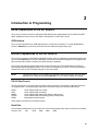
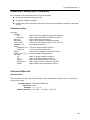
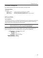
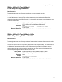
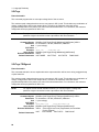
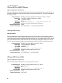
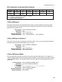
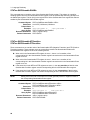
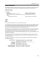
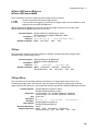
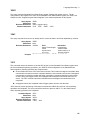
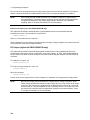
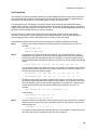
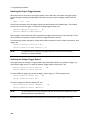
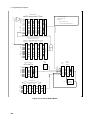
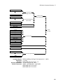
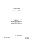
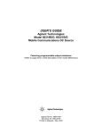
The SCPI Command Tree
As previously explained, the basic SCPI communication method involves sending one or more properly
formatted commands from the SCPI command tree to the instrument as program messages. The
following figure shows a portion of a subsystem command tree, from which you access the commands
located along the various paths (you can see the complete tree in appendix A).
ROOT
:OUTPut
[:STATe]
:COUPling
:DFI
[:STATe]
:SOURce
:PROTection
:CLEar
:DELay
:STATus
:OPERation
[:EVEN]
?
:CONDition?
Figure 2-1. Partial Command Tree
The Root Level
Note the location of the ROOT node at the top of the tree. Commands at the root level are at the top level
of the command tree. The SCPI interface is at this location when:
u the ac source is powered on
u a device clear (DCL) is sent to the ac source
u the SCPI interface encounters a message terminator
u the SCPI interface encounters a root specifier
Active Header Path
In order to properly traverse the command tree, you must understand the concept of the active header
path. When the ac source is turned on (or under any of the other conditions listed above), the active path
is at the root. That means the SCPI interface is ready to accept any command at the root level, such as
OUTPut or STATe.
If you enter OUTPut, the active header path moves one colon to the right . The interface is now ready to
accept :STATe, :COUPling, :DFI, or :PROTection as the next header. You must include the colon,
because it is required between headers.
If you now enter :PROTection, the active path again moves one colon to the right. The interface is now
ready to accept either :CLEar or :DELay as the next header.
18
Introduction to Programming - 2
If you now enter :CLEar, you have reached the end of the command string. The active header path
remains at :CLEar. If you wished, you could have entered :CLEar;DELay 20 and it would be accepted as
a compound message consisting of:
OUTPut:PROTection:CLEAr
and
OUTPut:PROTection:DELay 20.
The entire message would be:
OUTPut:PROTection:CLEar;DELay 20
The message terminator after DELay 20 returns the path to the root.
The Effect of Optional Headers
If a command includes optional headers, the interface assumes they are there. For example, if you enter
OUTPut OFF, the interface recognizes it as OUTPut:STATe OFF. This returns the active path to the root
(:OUTPut). But if you enter |OUTPut:STATe OFF,| then the active path remains at :STATe. This allows
you to send
OUTPut:STATe OFF;PROTection:CLEar
in one message. If you tried to send
OUTPut OFF;PROTection:CLEar
the header path would return to :OUTPut instead of :PROTection.
The optional header [SOURce] precedes the current, frequency, function, phase, pulse, list, and voltage
subsystems. This effectively makes :CURRent, :FREQuency, :FUNCtion, :PHASe, :PULse, :LIST, and
:VOLTage root-level commands.
Moving Among Subsystems
In order to combine commands from different subsystems, you need to be able to restore the active path
to the root. You do this with the root specifier (:). For example, you could clear the output protection and
check the status of the Operation Condition register as follows:
OUTPut:PROTection:CLEAr
STATus:OPERation:CONDition?
Because the root specifier resets the command parser to the root, you can use the root specifier and do
the same thing in one message:
OUTPut:PROTection:CLEAr;:STATus:OPERation:CONDition?
The following message shows how to combine commands from different subsystems as well as within the
same subsystem:
VOLTage:LEVel 70;PROTection 80;:CURRent:LEVel 3;PROTection:STATe ON
Note the use of the optional header LEVel to maintain the correct path within the voltage and current
subsystems and the use of the root specifier to move between subsytems.
NOTE:
The "Enhanced Tree Walking Implementation" given in appendix A of the IEEE 488.2
standard is not implemented in the ac source.
19
2 - Introduction to Programming
Including Common Commands
You can combine common commands with system commands in the same message. Treat the common
command as a message unit by separating it with a semicolon (the message unit separator). Common
commands do not affect the active header path; you may insert them anywhere in the message.
VOLTage:TRIGger 7.5;INITialize;*TRG
OUTPut OFF;*RCL 2;OUTPut ON
Using Queries
Observe the following precautions with queries:
u Set up the proper number of variables for the returned data.
u Read back all the results of a query before sending another command to the ac source. Otherwise
a Query Interrupted error will occur and the unreturned data will be lost.
Coupled Commands
When commands are coupled it means that the value sent by one command is affected by the settings of
the other commands. The following commands are coupled in the ac source:
u the voltage, voltage offset, and function shape commands
u the step, pulse, and list commands that control output voltages, voltage offsets, and function
shapes
u the pulse commands that program the width, duty cycle, period, and the hold parameter
u the voltage range and current limit commands in some ac source models
As explained later in Chapter 4, the order in which data is sent by these coupled commands can be
important when more than one parameter is changed.
Structure of a SCPI Message
SCPI messages consist of one or more message units ending in a message terminator. The terminator is
not part of the syntax, but implicit in the way your programming language indicates the end of a line (such
as a newline or end-of-line character).
The Message Unit
The simplest SCPI command is a single message unit consisting of a command header (or keyword)
followed by a message terminator.
ABORt<newline>
VOLTage?<newline>
The message unit may include a parameter after the header. The parameter usually is numeric, but it can
be a string:
VOLTage 20<newline>
VOLTage MAX<newline>
20
Introduction to Programming - 2
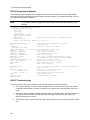
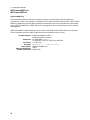
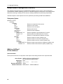
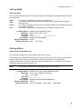
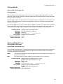
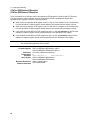
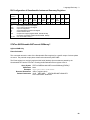
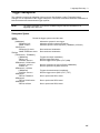
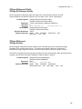
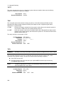
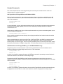
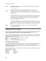
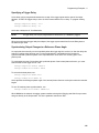
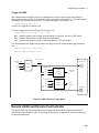
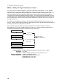
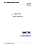
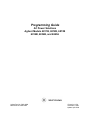
Combining Message Units
The following command message is briefly described here, with details in subsequent paragraphs.
Data
Message Unit
Headers
Query Indicator
VOLT:LEV
80
;
PROT 88
Header Separator
;:
CURR? <NL>
Message Terminator
Message Unit Separators
Root Specifier
Figure 2-2. Command Message Structure
The basic parts of the above message are:
Message Component
Headers
Header Separator
Data
Data Separator
Message Units
Message Unit Separator
Root Specifier
Query Indicator
Message Terminator
Example
VOLT LEV PROT CURR
The colon in VOLT:LEV
8088
The space in VOLT 80 and PROT 88
VOLT:LEV 80 PROT 88 CURR?
The semicolons in VOLT:LEV 80; and PROT 88;
The colon in PROT 88;:CURR?
The question mark in CURR?
The <NL> (newline) indicator. Terminators are not part of the SCPI syntax
Headers
Headers are instructions recognized by the ac source. Headers (which are sometimes known as
"keywords") may be either in the long form or the short form.
Long Form
The header is completely spelled out, such as VOLTAGE, STATUS, and DELAY.
Short Form
The header has only the first three or four letters, such as VOLT, STAT, and DEL.
The SCPI interface is not sensitive to case. It will recognize any case mixture, such as TRIGGER, Trigger,
TRIGger.
NOTE:
Short form headers result in faster program execution.
21
2 - Introduction to Programming
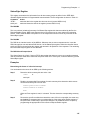
Header
Convention
In the command descriptions in Chapter 3 of this manual, headers are emphasized with
boldface type. The proper short form is shown in upper-case letters, such as DELay.
Header
Separator
If a command has more than one header, you must separate them with a colon
(VOLT:PROT OUTPut:RELay:POLarity).
Optional
Headers
The use of some headers is optional. Optional headers are shown in brackets, such as
OUTPut[:STATe] ON. As previously explained under "The Effect of Optional Headers", if
you combine two or more message units into a compound message, you may need to
enter the optional header.
Query Indicator
Following a header with a question mark turns it into a query (VOLTage?, VOLTage:PROTection?). If a
query contains a parameter, place the query indicator at the end of the last header
(VOLTage:PROTection? MAX).
Message Unit Separator
When two or more message units are combined into a compound message, separate the units with a
semicolon (STATus:OPERation?;QUEStionable?).
Root Specifier
When it precedes the first header of a message unit, the colon becomes the root specifier. It tells the
command parser that this is the root or the top node of the command tree. Note the difference between
root specifiers and header separators in the following examples:
OUTPut:PROTection:DELay .1
:OUTPut:PROTection:DELay .1
OUTPut:PROTection:DELay .1;:VOLTage 12.5
NOTE:
All colons are header separators
Only the first colon is a root specifier
Only the third colon is a root specifier
You do not have to precede root-level commands with a colon; there is an implied colon in
front of every root-level command.
Message Terminator
A terminator informs SCPI that it has reached the end of a message. Three permitted messages
terminators are:
u newline (<NL>), which is ASCII decimal 10 or hex 0A.
u end or identify (<END>)
u both of the above (<NL><END>).
In the examples of this guide, there is an assumed message terminator at the end of each message. If the
terminator needs to be shown, it is indicated as <NL> regardless of the actual terminator character.
22
Introduction to Programming - 2
SCPI Data Formats
All data programmed to or returned from the ac source is ASCII. The data may be numerical or character
string.
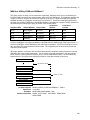
Numerical Data Formats
Symbol
Data Form
Talking Formats
<NR1>
Digits with an implied decimal point assumed at the right of the least-significant digit.
Examples: 273
<NR2>
Digits with an explicit decimal point. Example: .0273
<NR3>
Digits with an explicit decimal point and an exponent. Example: 2.73E+2
<Bool>
Boolean Data. Example: 0 | 1 or OFF | ON (0 = OFF; 1 = ON)
Listening Formats
<Nrf>
Extended format that includes <NR1>, <NR2> and <NR3>. Examples: 273273.
2.73E2
<Nrf+>
Expanded decimal format that includes <NRf> and MINMAX. Examples: 273 73.2 .73E2
MAX. MIN and MAX are the minimum and maximum limit values that are implicit in the
range specification for the parameter.
<Bool>
Boolean Data. Example: 0 | 1
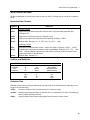
Suffixes and Multipliers
Class
Current
Amplitude
Time
Frequency
Suffix
A
V
S
HZ
1E3
1E-3
1E-6
Unit
ampere
volt
second
Hertz
Common Multipliers
K
M
U
Unit with Multiplier
MA (milliampere)
MV (millivolt)
MS (millisecond)
KHZ (kilohertz)
kilo
milli
micro
Character Data
Character strings returned by query statements may take either of the following forms, depending on the
length of the returned string:
<CRD>
Character Response Data. Permits the return of character strings.
<AARD>
Arbitrary ASCII Response Data. Permits the return of undelimited 7-bit ASCII. This data type
has an implied message terminator.
<SRD>
String Response Data. Returns string parameters enclosed in double quotes.
23
2 - Introduction to Programming
System Considerations
The remainder of this chapter addresses some system issues concerning programming. These are ac
source addressing and the use of the following types of GPIB system interfaces:
u HP Vectra PC controller with Agilent 82335A GPIB Interface Command Library
u IBM PC controller with National Instruments GPIB-PCII Interface/Handler
u Agilent controller with Agilent BASIC Language System
Assigning the GPIB Address in Programs
The ac source address cannot be set remotely. It must be set from the front panel. Once the address is
set, you can assign it inside programs. The following examples assume that the GPIB select code is 7,
and the ac source will be assigned to the variable ACS.
1070 ACS=706
1070 ASSIGN @ACS TO 706
! Agilent 82335A Interface
! Agilent BASIC Interface
For systems using the National Instruments DOS driver, the address is specified in the software
configuration program (IBCONFIG.EXE) and assigned a symbolic name. The address then is referenced
only by this name within the application program (see the National Instruments GPIB documentation).
Types of DOS Drivers
The Agilent 82335A and National Instruments GPIB are two popular DOS drivers. Each is briefly
described here. See the software documentation supplied with the driver for more details.
Agilent 82335A Driver
For GW-BASIC programming, the GPIB library is implemented as a series of subroutine calls. To access
these subroutines, your application program must include the header file SETUP.BAS, which is part of the
DOS driver software.
SETUP.BAS starts at program line 5 and can run up to line 999. Your application programs must begin at
line 1000. SETUP.BAS has built-in error checking routines that provide a method to check for GPIB errors
during program execution. You can use the error-trapping code in these routines or write your own code
using the same variables as used by SETUP.BAS.
National Instruments GPIB Driver
Your program must include the National Instruments header file DECL.BAS. This contains the initialization
code for the interface. Prior to running any applications programs, you must set up the interface with the
configuration program (IBCONF.EXE).
Your application program will not include the ac source symbolic name and GPIB address. These must
be specified during configuration (when you run IBCONF.EXE). Note that the primary address range is
from 0 to 30 but any secondary address must be specified in the address range of 96 to 126. The
instrument expects a message termination on EOI or line feed, so set EOI w/last byte of Write. It is also
recommended that you set Disable Auto Serial Polling.
All function calls return the status word IBSTA%, which contains a bit (ERR) that is set if the call results in
an error. When ERR is set, an appropriate code is placed in variable IBERR%. Be sure to check IBSTA%
after every function call. If it is not equal to zero, branch to an error handler that reads IBERR% to extract
the specific error.
24
Introduction to Programming - 2
Error Handling
If there is no error-handling code in your program, undetected errors can cause unpredictable results. This
includes "hanging up" the controller and forcing you to reset the system. Both of the above DOS drivers
have routines for detecting program execution errors.
Important
Use error detection after every call to a subroutine.
Agilent BASIC Controllers
The Agilent BASIC Programming Language provides access to GPIB functions at the operating system
level. This makes it unnecessary to have the header files required in front of DOS applications programs.
Also, you do not have to be concerned about controller "hangups" as long as your program includes a
timeout statement. Because the ac source can be programmed to generate SRQ on errors, your program
can use an SRQ service routine for decoding detected errors. The detectable errors are listed in Appendix
C.
25
3
Language Dictionary
Introduction
This section gives the syntax and parameters for all the IEEE 488.2 SCPI commands and the Common
commands used by the ac sources when operating in Normal mode. It is assumed that you are familiar
with the material in Chapter 2 "Introduction to Programming". Because the SCPI syntax remains the same
for all programming languages, the examples given for each command are generic.
Syntax Forms
Syntax definitions use the long form, but only short form headers (or "keywords")
appear in the examples. Use the long form to help make your program selfdocumenting.
Parameters
Most commands require a parameter and all queries will return a parameter.The range
for a parameter may vary according to the model of ac source. Parameters for all
models are listed in the Specifications table in the User’s Guide.
Models
If a command only applies to specific models, those models are listed in the <Model>
Only entry. If there is no <Model> Only entry, the command applies to all models.
Phases
If a command can apply to individual phases of an , the entry Phase Selectable will
appear in the command description.
Related
Commands
Where appropriate, related commands or queries are included. These are listed
because they are either directly related by function, or because reading about them will
clarify or enhance your understanding of the original command or query.
Order of
Presentation
The dictionary is organized as follows:
u Subsystem commands, arranged by subsystem
u IEEE 488.2 common commands
27
3 - Language Dictionary
Subsystem Commands
Subsystem commands are specific to functions. They can be a single command or a group of
commands. The groups are comprised of commands that extend one or more levels below the root. The
description of common commands follows the description of the subsystem commands.
The subsystem command groups are listed in alphabetical order and the commands within each
subsystem are grouped alphabetically under the subsystem. Commands followed by a question mark (?)
take only the query form. When commands take both the command and query form, this is noted in the
syntax descriptions.
You will find the subsystem command groups discussed on the following pages:
Subsystem
Page
Calibration Subsystem
29
Display Subsystem
34
Instrument Subsystem
35
Measurement Subsystem (Arrays)
37
Measurement Subsystem (Current)
42
Measurement Subsystem (Frequency)
48
Measurement Subsystem (Power)
49
Measurement Subsystem (Voltage)
52
Output Subsystem
55
Sense Subsystem
60
Source Subsystem (Current)
62
Source Subsystem (Frequency)
65
Source Subsystem (Function)
68
Source Subsystem (List)
71
Source Subsystem (Phase)
80
Source Subsystem (Pulse)
82
Source Subsystem (Voltage)
85
Status Subsystem
94
System Commands
102
Trace Subsystem
105
Trigger Subsystem
107
Common Commands
113
28
Language Dictionary - 3
Calibration Subsystem Commands
The commands in this subsystem allow you to do the following:
u Enable and disable the calibration mode
u Change the calibration password
u Calibrate the current and voltage output levels, and store new calibration constants in nonvolatile
memory.
Subsystem Syntax
CALibrate
:CURRent
:AC
:MEASure
:DATA <n>
:IMPedance
:LEVel <level>
:PASSword <n>
:PWM
:FREQuency <n>
:RAMP <n>
:SAVE
:STATE <bool> [,<n>]
:VOLTage
:AC
:DC
:OFFSet
:PROTection
:RTIMe
Begin ac current programming calibration sequence
Begin current measurement calibration sequence
Input a calibration measurement
Begin output impedance calibration sequence
Advance to next calibration step (P1 | P2 | P3 | P4)
Set calibration password
Trim pulse width modulator frequency
Trim pulse width modulator ramp
Save new cal constants in non-volatile memory
Enable or disable calibration mode
Begin ac voltage calibration sequence
Begin dc voltage calibration sequence
Begin offset voltage calibration sequence
Begin voltage protection calibration sequence
Begin realtime voltage calibration sequence
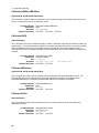
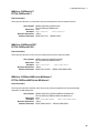
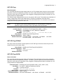
CALibrate:CURRent:AC
Phase Selectable
This command can only be used in the calibration mode. It initiates the calibration of the ac current limit
and metering circuits.
Command Syntax
Parameters
Examples
Related Commands
CALibrate:CURRent:AC
None
CAL:CURR:AC
CAL:STAT CAL:SAV
CAL:LEV
29
3 - Language Dictionary
CALibrate:CURRent:MEASure
Agilent 6811B, 6812B, 6813B, 6843A Only
This command is used to initiate the calibration of the current metering circuits and the peak current limit
circuits. It can only be used in the calibration mode.
Command Syntax
Parameters
Examples
Related Commands
CALibrate:CURRent:MEASure
None
CAL:CURR:MEAS
CAL:STAT CAL:SAV CAL:LEV
CALibrate:DATA
Phase Selectable
This command is only used in calibration mode. It enters a calibration value that you obtain by reading an
external meter. You must first select a calibration level (with CALibrate:LEVel) for the value being entered.
These constants are not stored in nonvolatile memory until they are saved with CALibrate:SAVE. If
CALibrate:STATE OFF is programmed without a CALibrate:SAVE, the previous calibration constants are
restored.
Command Syntax
Parameters
Unit
Examples
Related Commands
CALibrate:DATA <NRf>
<external reading>
A (amperes)
CAL:DATA 3222.3 MA
CAL:STAT CAL:SAV
CAL:DATA 5.000
CALibrate:IMPedance
Agilent 6811B, 6812B, 6813B, 6843A Only
This command can only be used in calibration mode. It calibrates the output impedance circuits. The
automatically performs the calibration and stores the impedance constant in nonvolatile memory.
CALibrate:IMPedance is a sequential command that takes several seconds to complete.
Command Syntax
Parameters
Examples
Related Commands
CALibrate:IMPedance
None
CAL:IMP
CAL:STAT CAL:SAV
CALibrate:LEVel
Phase Selectable
This command can only be used in calibration mode. It is used to advance to the next state in the
calibration sequence.
Command Syntax
Parameters
Examples
Related Commands
30
CALibrate:LEVel <level>
P1 | P2 | P3 | P4
CAL:LEV P2
CAL:STAT CAL:SAV
Language Dictionary - 3
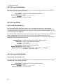
CALibrate:PASSword
This command can only be used in calibration mode. It allows you to change the calibration password. A
new password is automatically stored in nonvolatile memory and does not have to be stored with
CALibrate:SAVE. If the password is set to 0, password protection is removed and the ability to enter the
calibration mode is unrestricted.
Command Syntax
Parameters
Examples
Related Commands
CALibrate:PASSword <NRf>
0 (default)
CAL:PASS 6812
CAL:PASS 02.1997
CAL:STAT
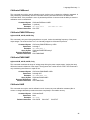
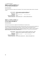
CALibrate:PWM:FREQuency
Agilent 6811B, 6812B, 6813B Only
This command is only used during manufacture or repair. It trims the switching frequency of the power
output stages. The numbers from 0 to 7 are internally mapped to 8 discrete frequencies.
Command Syntax
Parameters
Examples
Query Syntax
Returned Parameters
Related Commands
CALCulate:PWM:FREQuency <NRf>
0 through 7
CAL:PWM:FREQ 1
CALibrate:PWM:FREQuency?
<NR1>
CAL:PWM:RAMP
CALibrate:PWM:RAMP
Agilent 6811B, 6812B, 6813B, Only
This command modulates the slope of voltage ramp driving the power output stages. Varying the ramp
affects the harmonic distortion of the output. The argument is a number from 0 to 255. This command is
only used during manufacture or repair of the .
Command Syntax
Parameters
Examples
Query Syntax
Returned Parameters
Related Commands
CALCulate:PWM:RAMP <NRf>
0 through 255
CAL:PWM:RAMP 100
CALibrate:PWM:RAMP?
<NR1>
CAL:PWM:FREQ
CALibrate:SAVE
This command can only be used in calibration mode. It saves any new calibration constants (after a
current or voltage calibration procedure has been completed) in nonvolatile memory.
Command Syntax
Parameters
Examples
Related Commands
CALibrate:SAVE
None
CAL:SAVE
CAL:CURR CAL:VOLT
CAL:STAT
31
3 - Language Dictionary
CALibrate:STATe
This command enables and disables calibration mode. The calibration mode must be enabled before the
will accept any other calibration commands. The first parameter specifies the enabled or disabled state.
The second parameter is the password. It is required if the calibration mode is being enabled and the
existing password is not 0. If the password is not entered or is incorrect, an error is generated and the
calibration mode remains disabled. The query statement returns only the state, not the password.
Whenever the calibration state is changed from enabled to disabled, any new calibration constants are
lost unless they have been stored with CALibrate:SAVE.
Command Syntax
Parameters
*RST Value
Examples
Query Syntax
Returned Parameters
Related Commands
CALibrate:STATe <bool> [,<NRf>]
0 | 1 | OFF | ON [,<password>]
OFF
CAL:STAT 1,6812 CAL:STAT OFF
CALibrate:STATe?
<NR1>
CAL:PASS CAL:SAVE
CALibrate:VOLTage:AC
Phase Selectable
This command can only be used in calibration mode. It initiates the calibration of the ac voltage
programming and metering circuits.
Command Syntax
Parameters
Examples
Related Commands
CALibrate:VOLTage:AC
None
CAL:VOLT:AC
CAL:SAVE CAL:STAT
CALibrate:VOLTage:DC
Agilent 6811B, 6812B, 6813B, Only
This command can only be used in calibration mode. It initiates the calibration of the dc voltage
programming circuits.
Command Syntax
Parameters
Examples
Related Commands
32
CALibrate:VOLTage:DC
None
CAL:VOLT:DC
CAL:SAVE CAL:STAT
Language Dictionary - 3
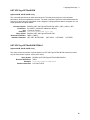
CALibrate:VOLTage:OFFSet
Agilent 6811B, 6812B, 6813B, Only
This command can only be used in calibration mode. It initiates the calibration of the offset voltage
programming circuits.
Command Syntax
Parameters
Examples
Related Commands
CALibrate:VOLTage:OFFSet
None
CAL:VOLT:OFFS
CAL:SAVE CAL:STAT CAL:LEV
CALibrate:VOLTage:PROTection
This command can only be used in calibration mode. It calibrates the overvoltage protection (OV) circuit.
The automatically performs the calibration and stores the new OV constant in nonvolatile memory.
CALibrate:VOLTage:PROTection is a sequential command that takes several seconds to complete.
Command Syntax
Parameters
Examples
Related Commands
CALibrate:VOLTage:PROTection
None
CAL:VOLT:PROT
CAL:SAVE CAL:STAT
CALibrate:VOLTage:RTIMe
Agilent 6843A Only
This command can only be used in calibration mode. It calibrates the realtime voltage programming
circuit.
Command Syntax
Parameters
Examples
Related Commands
CALibrate:VOLTage:RTIMe
None
CAL:VOLT:RTIM
CAL:SAVE CAL:STAT
33
3 - Language Dictionary
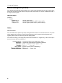
Display Subsystem Commands
This subsystem programs the front panel display of the ac source.
Subsystem Syntax
DISPlay
[:WINDow]
[:STATe] <bool>
:MODE <mode>
:TEXT
[:DATA] <display string>
Enable/disable front panel display
Set display mode (NORMal | TEXT)
Set text displayed in text mode
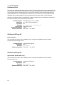
DISPlay
This command turns the front panel display on and off. It does not affect the annunciators.
Command Syntax
Parameters
*RST Value
Examples
Query Syntax
Returned Parameters
Related Commands
DISPlay[:WINDow]:STATe <bool>
0 | 1 | OFF | ON
ON
DISP:STAT 1, DISP:STAT OFF
DISPlay[:WINDow]:STATe?
0 | 1
DISP:MODE DISP:TEXT
DISPlay:MODE
This command sets the display to show either normal instrument functions, or to show a text message.
Text messages are defined with DISPlay:TEXT:DATA.
Command Syntax
Parameters
*RST Value
Examples
Query Syntax
Returned Parameters
Related Commands
DISPlay[:WINDow]:MODE <mode>
NORMal | TEXT
NORMal
DISP:MODE TEXT
DISPlay[:WINDow]:MODE?
<CRD>
DISP DISP:TEXT
DISPlay:TEXT
This command sets the character string that is displayed when the display mode is set to TEXT. The
argument is a quoted string limited to upper case alpha characters and numbers. The display is capable
of showing up to 14 characters. If the string exceeds the display capacity, it will be truncated.
Command Syntax
Parameters
*RST Value
Examples
Query Syntax
Returned Parameters
Related Commands
34
DISPlay[:WINDow]:TEXT[:DATA] <display_string>
<display_string>
null string
DISP:TEXT “DO TEST1”
DISPlay[:WINDow]:TEXT?
<SRD> (the last programmed string)
DISP DISP:MODE
Language Dictionary - 3
Instrument Subsystem
This subsystem programs the three-phase output capability of the Agilent 6834B .
Subsystem Syntax
INSTrument
:COUPle <phase>
:NSELect <n>
:SELect <output>
Couple all phases for programming (ALL | NONE)
Select the output phase to program (1 | 2 | 3)
Select the output phase to program (OUTP1 | OUTP2 | OUTP3)
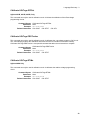
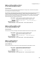
INSTrument:COUPle
Agilent 6834B Only
In a three-phase power source it is convenient to set parameters of all three output phases simultaneously
with one programming command. When INST:COUP ALL is programmed, sending a command to any
phase will result in that command being sent to all three phases.
NOTE:
INSTrument:COUPle only affects the operation of subsequent commands. It does not by
itself immediately affect the ’s output. The commands that are affected by
INSTrument:COUPle are those with the designation: Phase Selectable.
INSTrument:COUPle has no affect on queries. There is no way to query more than one phase with a
single command. Directing queries to individual phases is done with INSTrument:NSELect.
Command Syntax
Parameters
*RST Value
Examples
Query Syntax
Returned Parameters
Related Commands
INSTrument:COUPle <phase>
ALL | NONE
ALL
INST:COUP ALL
INSTrument:COUPle?
<CRD>
INST:NSEL
35
3 - Language Dictionary
INSTrument:NSELect
INSTrument:SELect
Agilent 6834B Only
These commands allow the selection of individual outputs in a three-phase model for subsequent
commands or queries. Their operation is dependent on the setting of INSTrument:COUPle. If INST:COUP
NONE is programmed, then the phase selectable commands are sent only to the particular output phase
set by INSTrument:NSELect. If INST:COUP ALL is programmed, then all commands are sent to all three
output phases.
INSTrument:NSELect selects the phase by its number, while INSTrument:SELect references it by name.
These commands also select which output phase returns data when a query is sent.
Command Syntax
Parameters
*RST Value
Examples
Query Syntax
Returned Parameters
Related Commands
36
INSTrument:NSELect <NR1>
INSTrument:SELect <output>
For INST:NSEL 1 | 2 | 3
For INST:SEL OUTPut1 | OUTPut2 | OUTPut3
1 or OUTPut1
INST:NSEL 3
INST:SEL OUTP1
INSTrument:NSELect?
<NR1>
INST:COUP
Language Dictionary - 3
Measurement Subsystem (Arrays)
This subsystem lets you retrieve arrays containing measurements data. Only current and voltage
measurements are stored in an array. Two measurement commands are available: MEASure and FETCh.
MEASure triggers the acquisition of new data before returning the readings from the array. FETCh returns
previously acquired data from the array.
Individual outputs of a three-phase source are specified by the setting of INSTrument:NSELect.
Subsystem Syntax
MEASure | FETCh
:ARRay
:CURRent
[:DC]?
Returns the digitized instantaneous current
:HARMonic
[:AMPLitude]?
Returns amplitudes of the first 50 harmonics
:PHASe?
Returns phase angles of the first 50 harmonics
:NEUTral
[:DC]?
Returns the neutral digitized instantaneous current (3-phase only)
:HARMonic
[:AMPLitude]? Returns neutral current harmonic amplitude
:PHASe?
Returns neutral current harmonic phase
:VOLTage
[:DC]?
Returns the digitized instantaneous voltage
:HARMonic
[:AMPLitude]?
Returns amplitudes of the first 50 harmonics
:PHASe?
Returns phase angles of the first 50 harmonics
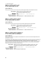
MEASure:ARRay:CURRent?
FETCh:ARRay:CURRent?
Phase Selectable
These queries return an array containing the instantaneous output current in amperes. The output voltage
and current are digitized whenever a measure command is given or whenever an acquire trigger occurs. If
digitization is caused by a measure command, the time interval between samples is determined by the
output frequency. For frequencies greater than 45Hz, the time interval is 25 microseconds. If digitization is
caused by an acquire trigger, the time interval is set by SENSe:SWEep:TINTerval, and the position of the
trigger relative to the beginning of the data buffer is determined by SENSe:SWEep:OFFSet:POINts.
Query Syntax
Parameters
Examples
Returned Parameters
Related Commands
MEASure:ARRay:CURRent[:DC]?
FETCh:ARRay:CURRent[:DC]?
None
MEAS:ARR:CURR?
FETC:ARR:CURR?
4096 NR3 values
MEAS:ARR:VOLT?
37
3 - Language Dictionary
MEASure:ARRay:CURRent:HARMonic?
FETCh:ARRay:CURRent:HARMonic?
Phase Selectable
These queries return an array of harmonic amplitudes of output current in rms amperes.
The first value returned is the dc component, the second value is the fundamental frequency, and so on
up to the 50th harmonic. Harmonic orders can be measured up to the fundamental measurement
bandwidth of the measurement system, which is 12.6kHz. Thus, the maximum harmonic that can be
measured is dependent on the output frequency. Any harmonics that represent frequencies greater than
12.6kHz are returned as 0.
Query Syntax
Parameters
Examples
Returned Parameters
Related Commands
MEASure:ARRay:CURRent:HARMonic[:AMPLitude]?
FETCh:ARRay:CURRent:HARMonic[:AMPLitude]?
None
MEAS:ARR:CURR:HARM?
FETC:ARR:CURR:HARM?
51 NR3 values
MEAS:ARR:VOLT:HARM? MEAS:ARR:CURR:HARM:PHAS?
MEASure:ARRay:CURRent:HARMonic:PHASe?
FETCh:ARRay:CURRent:HARMonic:PHASe?
Phase Selectable
These queries return an array of harmonic phases of output current in degrees, referenced to the positive
zero crossing of the fundamental component.
The first value returned is the dc component (always returned as 0 degrees phase) , the second value is
the fundamental frequency, and so on up to the 50th harmonic. Harmonic orders can be measured up to
the fundamental measurement bandwidth of the measurement system, which is 12.6kHz. Thus the
maximum harmonic that can be measured is dependent on the output frequency. Any harmonics that
represent frequencies greater than 12.6kHz are returned as 0.
Query Syntax
Parameters
Examples
Returned Parameters
Related Commands
38
MEASure:ARRay:CURRent:HARMonic:PHASe? <NRf>
FETCh:ARRay:CURRent:HARMonic:PHASe? <NRf>
None
MEAS:ARR:CURR:HARM:PHAS?
FETC:ARR:CURR:HARM:PHAS?
51 NR3 values
MEAS:ARR:VOLT:HARM:PHAS? MEAS:ARR:CURR:HARM?
Language Dictionary - 3
MEASure:ARRay:CURRent:NEUTral?
FETCh:ARRay:CURRent:NEUTral?
Agilent 6834B Only
These queries return an array containing the instantaneous output current of the neutral output terminal in
amperes.
The output voltage and current are digitized whenever a measure command is given or whenever an
acquire trigger occurs. If digitization is caused by a measure command, the time interval between samples
is determined by the output frequency. For frequencies greater than 45Hz, the time interval is 25
microseconds. If digitization is caused by an acquire trigger, the time interval is set by
SENSe:SWEep:TINTerval, and the position of the trigger relative to the beginning of the data buffer is
determined by SENSe:SWEep:OFFSet:POINts.
Query Syntax
Parameters
Examples
Returned Parameters
MEASure:ARRay:CURRent:NEUTral[:DC]?
FETCh:ARRay:CURRent:NEUTral[:DC]?
None
MEAS:ARR:CURR:NEUT?
FETC:ARR:CURR:NEUT?
4096 NR3 values
MEASure:ARRay:CURRent:NEUTral:HARMonic?
FETCh:ARRay:CURRent:NEUTral:HARMonic?
Agilent 6834B Only
These queries return an array of harmonic amplitudes of output current of the neutral output terminal in
rms amperes.
The first value returned is the dc component, the second value is the fundamental frequency, and so on
up to the 50th harmonic. Harmonic orders can be measured up to the fundamental measurement
bandwidth of the measurement system, which is 12.6kHz. Thus, the maximum harmonic that can be
measured is dependent on the output frequency. Any harmonics that represent frequencies greater than
12.6kHz are returned as 0.
Query Syntax
Parameters
Examples
Returned Parameters
Related Commands
MEASure:ARRay:CURRent:NEUTral:HARMonic[:AMPLitude]?
FETCh:ARRay:CURRent:NEUTral:HARMonic[:AMPLitude]?
None
MEAS:ARR:CURR:NEUT:HARM?
FETC:ARR:CURR:NEUT:HARM?
51 NR3 values
MEAS:ARR:CURR:NEUT:HARM:PHAS?
39
3 - Language Dictionary
MEASure:ARRay:CURRent:NEUTral:HARMonic:PHASe?
FETCh:ARRay:CURRent:NEUTral:HARMonic:PHASe?
Agilent 6834B Only
These queries return an array of harmonic phases of output current of the neutral output terminal in
degrees, referenced to the positive zero crossing of the fundamental component.
The first value returned is the dc component (always returned as 0 degrees phase) , the second value is
the fundamental frequency, and so on up to the 50th harmonic. Harmonic orders can be measured up to
the fundamental measurement bandwidth of the measurement system, which is 12.6kHz. Thus the
maximum harmonic that can be measured is dependent on the output frequency. Any harmonics that
represent frequencies greater than 12.6kHz are returned as 0.
Query Syntax
Parameters
Examples
Returned Parameters
Related Commands
MEASure:ARRay:CURRent:NEUTral:HARMonic:PHASe?
FETCh:ARRay:CURRent:NEUTral:HARMonic:PHASe?
None
MEAS:ARR:CURR:NEUT:HARM:PHAS?
FETC:ARR:CURR:NEUT:HARM:PHAS?
51 NR3 values
MEAS:ARR:CURR:NEUT:HARM?
MEASure:ARRay:VOLTage?
FETCh:ARRay:VOLTage?
Phase Selectable
These queries return an array containing the instantaneous output voltage in volts.
The output voltage and current are digitized whenever a measure command is given or whenever an
acquire trigger occurs. If digitization is caused by a measure command, the time interval between samples
is determined by the output frequency. For frequencies greater than 45Hz, the time interval is 25
microseconds. If digitization is caused by an acquire trigger, the time interval is set by
SENSe:SWEep:TINTerval, and the position of the trigger relative to the beginning of the data buffer is
determined by SENSe:SWEep:OFFSet:POINts.
Query Syntax
Parameters
Examples
Returned Parameters
Related Commands
40
MEASure:ARRay:VOLTage[:DC]?
FETCh:ARRay:VOLTage[:DC]?
None
MEAS:ARR:VOLT?
FETC:ARR:VOLT?
4096 NR3 values
MEAS:ARR:CURR?
Language Dictionary - 3
MEASure:ARRay:VOLTage:HARMonic?
FETCh:ARRay:VOLTage:HARMonic?
Phase Selectable
These queries return an array of harmonic amplitudes of output voltage in rms volts.
The first value returned is the dc component, the second value is the fundamental frequency, and so on
up to the 50th harmonic. Harmonic orders can be measured up to the fundamental measurement
bandwidth of the measurement system, which is 12.6kHz. Thus, the maximum harmonic that can be
measured is dependent on the output frequency. Any harmonics that represent frequencies greater than
12.6kHz are returned as 0.
Query Syntax
Parameters
Examples
Returned Parameters
Related Commands
MEASure:ARRay:VOLTage:HARMonic[:AMPLitude]?
FETCh:ARRay:VOLTage:HARMonic[:AMPLitude]?
None
MEAS:ARR:VOLT:HARM?
FETC:ARR:VOLT:HARM?
51 NR3 values
MEAS:ARR:CURR:HARM? MEAS:ARR:VOLT:HARM:PHAS?
MEASure:ARRay:VOLTage:HARMonic:PHASe?
FETCh:ARRay:VOLTage:HARMonic:PHASe?
Phase Selectable
These queries return an array of harmonic phases of output voltage in degrees, referenced to the positive
zero crossing of the fundamental component.
The first value returned is the dc component (always returned as 0 degrees phase) , the second value is
the fundamental frequency, and so on up to the 50th harmonic. Harmonic orders can be measured up to
the fundamental measurement bandwidth of the measurement system, which is 12.6kHz. Thus the
maximum harmonic that can be measured is dependent on the output frequency. Any harmonics that
represent frequencies greater than 12.6kHz are returned as 0.
Query Syntax
Parameters
Examples
Returned Parameters
Related Commands
MEASure:ARRay:VOLTage:HARMonic:PHASe? <NRf>
FETCh:ARRay:VOLTage:HARMonic:PHASe? <NRf>
None
MEAS:ARR:VOLT:HARM:PHAS?
FETC:ARR:VOLT:HARM:PHAS?
51 NR3 values
MEAS:ARR:CURR:HARM:PHAS? MEAS:ARR:VOLT:HARM?
41
3 - Language Dictionary
Measurement Subsystem (Current)
This subsystem programs the current measurement capability of the ac source. Two measurement
commands are available: MEASure and FETCh. MEASure triggers the acquisition of new measurement
data before returning a reading. FETCh returns a reading computed from previously acquired data.
Individual outputs of a three-phase source are specified by the setting of INSTrument:NSELect.
Subsystem Syntax
MEASure | FETCh
[:SCALar]
:CURRent
[:DC]?
:AC?
:ACDC?
:AMPLitude
:MAX?
:CREStfactor?
:HARMonic
[:AMPLitude]? <n>
:PHASe? <n>
:THD?
:NEUTral
[:DC]?
:AC?
:ACDC?
:HARMonic
[:AMPLitude]? <n>
:PHASe? <n>
Returns dc component of the current
Returns ac rms current
Returns ac+dc rms current
Returns peak current
Returns current crestfactor
Returns amplitude of the Nth harmonic of current
Returns phase of the Nth harmonic of current
Returns % of total harmonic distortion of current
Returns neutral dc current (3-phase only)
Returns neutral ac rms current (3-phase only)
Returns neutral ac+dc rms current (3-phase only)
Returns neutral current harmonic amplitude (3-phase only)
Returns neutral current harmonic phase (3-phase only)
MEASure:CURRent?
FETCh:CURRent?
Phase Selectable
These queries return the dc component of the output current being sourced at the output terminals.
Query Syntax
Parameters
Examples
Returned Parameters
Related Commands
42
MEASure:[SCALar]:CURRent[:DC]?
FETCh:[SCALar]:CURRent[:DC]?
None
MEAS:CURR?
FETC:CURR?
<NR3>
MEAS:VOLT? MEAS:CURR:AC?
Language Dictionary - 3
MEASure:CURRent:AC?
FETCh:CURRent:AC?
Phase Selectable
These queries return the ac component rms current being sourced at the output terminals.
Query Syntax
Parameters
Examples
Returned Parameters
Related Commands
MEASure:[SCALar]:CURRent:AC?
FETCh:[SCALar]:CURRent:AC?
None
MEAS:CURR:AC?
FETC:CURR:AC?
<NR3>
MEAS:VOLT:AC? MEAS:CURR?
MEASure:CURRent:ACDC?
FETCh:CURRent:ACDC?
Phase Selectable
These queries return the ac+dc rms current being sourced at the output terminals.
Query Syntax
Parameters
Examples
Returned Parameters
Related Commands
MEASure:[SCALar]:CURRent:ACDC?
FETCh:[SCALar]:CURRent:ACDC?
None
MEAS:CURR:ACDC?
FETC:CURR:ACDC?
<NR3>
MEAS:VOLT:ACDC? MEAS:CURR:AMPL:MAX?
MEASure:CURRent:AMPLitude:MAXimum?
FETCh:CURRent:AMPLitude:MAXimum?
Phase Selectable
These queries return the absolute value of the peak current as sampled over one measurement
acquisition of 4096 data points.
Query Syntax
Parameters
Examples
Returned Parameters
Related Commands
MEASure:[SCALar]:CURRent:AMPLitude:MAXimum?
FETCh:[SCALar]:CURRent:AMPLitude:MAXimum?
None
MEAS:CURR:AMPL:MAX?
FETC:CURR:AMPL:MAX?
<NR3>
MEAS:CURR:ACDC? MEAS:CURR:CRES?
43
3 - Language Dictionary
MEASure:CURRent:CREStfactor?
FETCh:CURRent:CREStfactor?
Phase Selectable
These queries return the output current crest factor. This is the ratio of peak output current to rms output
current.
Query Syntax
Parameters
Examples
Returned Parameters
Related Commands
MEASure:[SCALar]:CURRent:CREStfactor?
FETCh:[SCALar]:CURRent:CRESfactor?
None
MEAS:CURR:CRES?
FETC:CURR:CRES?
<NR3>
MEAS:CURR:ACDC? MEAS:CURR:AMPL:MAX?
MEASure:CURRent:HARMonic?
FETCh:CURRent:HARMonic?
Phase Selectable
These queries return the rms amplitude of the Nth harmonic of output current.
The parameter is the desired harmonic number. Queries sent with a value of 0 return the dc component. A
value of 1 returns the fundamental output frequency. Harmonic orders can be queried up to the
fundamental measurement bandwidth of the measurement system, which is 12.6kHz. Thus the maximum
harmonic that can be measured is dependent on the output frequency. Any harmonics that represent
frequencies greater than 12.6kHz are returned as 0.
Query Syntax
Parameters
Examples
Returned Parameters
Related Commands
44
MEASure:[SCALar]:CURRent:HARMonic[:AMPLitude]? <NRf>
FETCh:[SCALar]:CURRent:HARMonic[:AMPLitude]? <NRf>
0 to 50
MEAS:CURR:HARM? 3
FETC:CURR:HARM? 1
<NR3>
MEAS:CURR:HARM:PHAS? MEAS:CURR:HARM:THD?
Language Dictionary - 3
MEASure:CURRent:HARMonic:PHASe?
FETCh:CURRent:HARMonic:PHASe?
Phase Selectable
These queries return the phase angle of the Nth harmonic of output current, referenced to the positive
zero crossing of the fundamental component.
The parameter is the desired harmonic number. Queries sent with a value of 0 return the dc component. A
value of 1 returns the fundamental output frequency. Harmonic orders can be queried up to the
fundamental measurement bandwidth of the measurement system, which is 12.6kHz. Thus the maximum
harmonic that can be measured is dependent on the output frequency. Any harmonics that represent
frequencies greater than 12.6kHz are returned as 0.
Query Syntax
Parameters
Examples
Returned Parameters
Related Commands
MEASure:[SCALar]:CURRent:HARMonic:PHASe? <NRf>
FETCh:[SCALar]:CURRent:HARMonic:PHASe? <NRf>
0 to 50
MEAS:CURR:HARM:PHAS? 3
FETC:CURR:HARM:PHAS? 1
<NR3>
MEAS:CURR:HARM? MEAS:CURR:HARM:THD?
MEASure:CURRent:HARMonic:THD?
FETCh:CURRent:HARMonic:THD?
Phase Selectable
These queries return the percentage of total harmonic distortion and noise in the output current.
Query Syntax
Parameters
Examples
Returned Parameters
Related Commands
MEASure:[SCALar]:CURRent:HARMonic:THD?
FETCh:[SCALar]:CURRent:HARMonic:THD?
None
MEAS:CURR:HARM:THD?
FETC:CURR:HARM:THD?
<NR3>
MEAS:CURR:HARM? MEAS:CURR:HARM:PHAS?
MEASure:CURRent:NEUTral?
FETCh:CURRent:NEUTral?
Agilent 6834B Only
These queries return the dc current in the neutral output terminal of a three-phase ac source.
Query Syntax
Parameters
Examples
Returned Parameters
Related Commands
MEASure:[SCALar]:CURRent:NEUTral[:DC]?
FETCh:[SCALar]:CURRent:NEUTral[:DC]?
None
MEAS:CURR:NEUT?
FETC:CURR:NEUT?
<NR3>
MEAS:CURR:NEUT:AC? MEAS:CURR:NEUT:ACDC?
45
3 - Language Dictionary
MEASure:CURRent:NEUTral:AC?
FETCh:CURRent:NEUTral:AC?
Agilent 6834B Only
These queries return the ac rms current in the neutral output terminal of a three-phase ac source.
Query Syntax
Parameters
Examples
Returned Parameters
Related Commands
MEASure:[SCALar]:CURRent:NEUTral:AC?
FETCh:[SCALar]:CURRent:NEUTral:AC?
None
MEAS:CURR:NEUT:AC?
FETC:CURR:NEUT:AC?
<NR3>
MEAS:CURR:NEUT? MEAS:CURR:NEUT:ACDC?
MEASure:CURRent:NEUTral:ACDC?
FETCh:CURRent:NEUTral:ACDC?
Agilent 6834B Only
These queries return the ac+dc rms current in the neutral output terminal of a three-phase .
Query Syntax
Parameters
Examples
Returned Parameters
Related Commands
MEASure:[SCALar]:CURRent:NEUTral:ACDC?
FETCh:[SCALar]:CURRent:NEUTral:ACDC?
None
MEAS:CURR:NEUT:ACDC?
FETC:CURR:NEUT:ACDC?
<NR3>
MEAS:CURR:NEUT? MEAS:CURR:NEUT:AC?
MEASure:CURRent:NEUTral:HARMonic?
FETCh:CURRent:NEUTral:HARMonic?
Agilent 6834B Only
These queries return the rms amplitude of the Nth harmonic of current in the neutral output terminal of a
three-phase ac source.
The parameter is the desired harmonic number. Queries sent with a value of 0 return the dc component. A
value of 1 returns the fundamental output frequency. Harmonic orders can be queried up to the
fundamental measurement bandwidth of the measurement system, which is 12.6kHz. Thus the maximum
harmonic that can be measured is dependent on the output frequency. Any harmonics that represent
frequencies greater than 12.6kHz are returned as 0.
Query Syntax
Parameters
Examples
Returned Parameters
Related Commands
46
MEASure:[SCALar]:CURRent:NEUTral:HARMonic[:AMPLitude]? <NRf>
FETCh:[SCALar]:CURRent:NEUTral:HARMonic[:AMPLitude]? <NRf>
0 to 50
MEAS:CURR:NEUT:HARM? 3
FETC:CURR:NEUT:HARM? 1
<NR3>
MEAS:CURR:NEUT:HARM:PHAS?
Language Dictionary - 3
MEASure:CURRent:NEUTral:HARMonic:PHASe?
FETCh:CURRent:NEUTral:HARMonic:PHASe?
Agilent 6834B Only
These queries return the phase angle of the Nth harmonic of current in the neutral output terminal of a
three-phase ac source, referenced to the positive zero crossing of the fundamental component.
The parameter is the desired harmonic number. Queries sent with a value of 0 return the dc component. A
value of 1 returns the fundamental output frequency. Harmonic orders can be queried up to the
fundamental measurement bandwidth of the measurement system, which is 12.6kHz. Thus the maximum
harmonic that can be measured is dependent on the output frequency. Any harmonics that represent
frequencies greater than 12.6kHz are returned as 0.
Query Syntax
Parameters
Examples
Returned Parameters
Related Commands
MEASure:[SCALar]:CURRent:NEUTral:HARMonic:PHASe? <NRf>
FETCh:[SCALar]:CURRent:NEUTral:HARMonic:PHASe? <NRf>
0 to 50
MEAS:CURR:NEUT:HARM:PHAS? 3
FETC:CURR:NEUT:HARM:PHAS? 1
<NR3>
MEAS:CURR:NEUT:HARM?
47
3 - Language Dictionary
Measurement Subsystem (Frequency)
This subsystem programs the frequency measurement capability of the ac source. Two measurement
commands are available: MEASure and FETCh. MEASure triggers the acquisition of new measurement
data before returning a reading. FETCh returns a reading computed from previously acquired data.
Subsystem Syntax
MEASure | FETCh
[:SCALar]
:FREQuency?
Returns the output frequency
MEASure:FREQuency?
FETCh:FREQuency?
This query returns the output frequency in Hertz.
Query Syntax
Parameters
Examples
Returned Parameters
48
MEASure:[SCALar]:FREQuency?
FETCh:[SCALar]:FREQuency?
None
MEAS:FREQ?
FETC:FREQ?
<NR3>
Language Dictionary - 3
Measurement Subsystem (Power)
This subsystem programs the power measurement capability of the ac source. Two measurement
commands are available: MEASure and FETCh. MEASure triggers the acquisition of new measurement
data before returning a reading. FETCh returns a reading computed from previously acquired data.
Individual outputs of a three-phase source are specified by the setting of INSTrument:NSELect.
Subsystem Syntax
MEASure | FETCh
[:SCALar]
:POWer
[:DC]?
:AC
[:REAL]?
:APParent?
:REACtive?
:PFACtor?
:TOTal?
Returns the dc component of power
Returns real power
Returns VA
Returns VAR
Returns power factor
Returns real 3-phase total power
MEASure:POWer?
FETCh:POWer?
Phase Selectable
These queries return the dc component of the power being sourced at the output terminals in watts.
Query Syntax
Parameters
Examples
Returned Parameters
Related Commands
MEASure:[SCALar]:POWer[:DC]?
FETCh:[SCALar]:POWer[:DC]?
None
MEAS:POW?
FETC:POW?
<NR3>
MEAS:POW:AC?
MEASure:POWer:AC?
FETCh:POWer:AC?
Phase Selectable
These queries return the in-phase component of power being sourced at the output terminals in watts.
Query Syntax
Parameters
Examples
Returned Parameters
Related Commands
MEASure:[SCALar]:POWer:AC[:REAL]?
FETCh:[SCALar]:POWer:AC[:REAL]?
None
MEAS:POW:AC?
FETC:POW:AC?
<NR3>
MEAS:POW?
49
3 - Language Dictionary
MEASure:POWer:AC:APParent?
FETCh:POWer:AC:APParent?
Phase Selectable
These queries return the apparent power being sourced at the output terminals in volt-amperes.
Query Syntax
Parameters
Examples
Returned Parameters
Related Commands
MEASure:[SCALar]:POWer:AC:APParent?
FETCh:[SCALar]:POWer:AC:APParent?
None
MEAS:POW:AC:APP?
FETC:POW:AC:APP?
<NR3>
MEAS:POW:REAC? MEAS:POW:PFAC?
MEASure:POWer:AC:REACtive?
FETCh:POWer:AC:REACtive?
Phase Selectable
These queries return the reactive power being sourced at the output terminals in volt-amperes reactive.
Reactive power is computed as:
VAR = sqrt(square(apparent power) square(real power))
Query Syntax
Parameters
Examples
Returned Parameters
Related Commands
MEASure:[SCALar]:POWer:AC:REACtive?
FETCh:[SCALar]:POWer:AC:REACtive?
None
MEAS:POW:AC:REAC?
FETC:POW:AC:REAC?
<NR3>
MEAS:POW:AC:APP? MEAS:POW:PFAC?
MEASure:POWer:AC:PFACtor?
FETCh:POWer:AC:PFACtor?
Phase Selectable
These queries return the output power factor. The power factor is computed as:
pfactor = real power/apparent power
Query Syntax
Parameters
Examples
Returned Parameters
Related Commands
50
MEASure:[SCALar]:POWer:AC:PFACtor?
FETCh:[SCALar]:POWer:AC:PFACtor?
None
MEAS:POW:AC:PFAC?
FETC:POW:AC:PFAC?
<NR3>
MEAS:POW:AC:APP? MEAS:POW:REAC?
Language Dictionary - 3
MEASure:POWer:AC:TOTal?
FETCh:POWer:AC:TOTal?
Agilent 6834B Only
These queries return the total power being sourced at the output terminals of a three-phase ac source.
Query Syntax
Parameters
Examples
Returned Parameters
MEASure:[SCALar]:POWer:AC:TOTal?
FETCh:[SCALar]:POWer:AC:TOTal?
None
MEAS:POW:AC:TOT?
FETC:POW:AC:TOT?
<NR3>
51
3 - Language Dictionary
Measurement Subsystem (Voltage)
This subsystem programs the voltage measurement capability of the ac source. Two measurement
commands are available: MEASure and FETCh. MEASure triggers the acquisition of new measurement
data before returning a reading. FETCh returns a reading computed from previously acquired data.
Individual outputs of a three-phase source are specified by the setting of INSTrument:NSELect.
Subsystem Syntax
MEASure | FETCh
[:SCALar]
:VOLTage
[:DC]?
:AC?
:ACDC?
:HARMonic
[:AMPLitude]? <n>
:PHASe? <n>
:THD?
Returns dc component of the voltage
Returns ac rms voltage
Returns ac+dc rms voltage
Returns amplitude of the Nth harmonic of voltage
Returns phase of the Nth harmonic of voltage
Returns % of total harmonic distortion of voltage
MEASure:VOLTage?
FETCh:VOLTage?
Phase Selectable
These queries return the dc component of the output voltage being sourced at the output terminals.
Query Syntax
Parameters
Examples
Returned Parameters
Related Commands
MEASure:[SCALar]:VOLTage[:DC]?
FETCh:[SCALar]:VOLTage[:DC]?
None
MEAS:VOLT?
FETC:VOLT?
<NR3>
MEAS:CURR? MEAS:VOLT:AC?
MEASure:VOLTage:AC?
FETCh:VOLTage:AC?
Phase Selectable
These queries return the ac rms voltage being sourced at the output terminals.
Query Syntax
Parameters
Examples
Returned Parameters
Related Commands
52
MEASure:[SCALar]:VOLTage:AC?
FETCh:[SCALar]:VOLTage:AC?
None
MEAS:VOLT:AC?
FETC:VOLT:AC?
<NR3>
MEAS:CURR:AC? MEAS:VOLT?
Language Dictionary - 3
MEASure:VOLTage:ACDC?
FETCh:VOLTage:ACDC?
Phase Selectable
These queries return the ac+dc rms voltage being sourced at the output terminals.
Query Syntax
Parameters
Examples
Returned Parameters
Related Commands
MEASure:[SCALar]:VOLTage:ACDC?
FETCh:[SCALar]:VOLTage:ACDC?
None
MEAS:VOLT:ACDC?
FETC:VOLT:ACDC?
<NR3>
MEAS:CURR:ACDC? MEAS:VOLT?
MEASure:VOLTage:HARMonic?
FETCh:VOLTage:HARMonic?
Phase Selectable
These queries return the rms amplitude of the Nth harmonic of output voltage.
The parameter is the desired harmonic number. Queries sent with a value of 0 return the dc component. A
value of 1 returns the fundamental output frequency. Harmonic orders can be queried up to the
fundamental measurement bandwidth of the measurement system, which is 12.6kHz. Thus the maximum
harmonic that can be measured is dependent on the output frequency. Any harmonics that represent
frequencies greater than 12.6kHz are returned as 0.
Query Syntax
Parameters
Examples
Returned Parameters
Related Commands
MEASure:[SCALar]:VOLTage:HARMonic[:AMPLitude]? <NRf>
FETCh:[SCALar]:VOLTage:HARMonic[:AMPLitude]? <NRf>
0 to 50
MEAS:VOLT:HARM? 3
FETC:VOLT:HARM? 1
<NR3>
MEAS:VOLT:HARM:PHAS? MEAS:VOLT:HARM:THD?
53
3 - Language Dictionary
MEASure:VOLTage:HARMonic:PHASe?
FETCh:VOLTage:HARMonic:PHASe?
Phase Selectable
These queries return the phase angle of the Nth harmonic of output voltage, referenced to the positive
zero crossing of the fundamental component.
The parameter is the desired harmonic number. Queries sent with a value of 0 return the dc component. A
value of 1 returns the fundamental output frequency. Harmonic orders can be queried up to the
fundamental measurement bandwidth of the measurement system, which is 12.6kHz. Thus the maximum
harmonic that can be measured is dependent on the output frequency. Any harmonics that represent
frequencies greater than 12.6kHz are returned as 0.
Query Syntax
Parameters
Examples
Returned Parameters
Related Commands
MEASure:[SCALar]:VOLTage:HARMonic:PHASe? <NRf>
FETCh:[SCALar]:VOLTage:HARMonic:PHASe? <NRf>
0 to 50
MEAS:VOLT:HARM:PHAS? 3
FETC:VOLT:HARM:PHAS? 1
<NR3>
MEAS:VOLT:HARM? MEAS:VOLT:HARM:THD?
MEASure:VOLTage:HARMonic:THD?
FETCh:VOLTage:HARMonic:THD?
Phase Selectable
These queries return the percentage of total harmonic distortion and noise in the output voltage.
Query Syntax
Parameters
Examples
Returned Parameters
Related Commands
54
MEASure:[SCALar]:VOLTage:HARMonic:THD?
FETCh:[SCALar]:VOLTage:HARMonic:THD?
None
MEAS:VOLT:HARM:THD?
FETC:VOLT:HARM:THD?
<NR3>
MEAS:VOLT:HARM? MEAS:VOLT:HARM:PHAS?
Language Dictionary - 3
Output Subsystem
This subsystem controls the main outputs, the signal outputs, the power-on state, and the output
protection function of the ac source.
Subsystem Syntax
OUTPut
[:STATe] <bool>
:COUPling <coupling>
:DFI
[:STATE] <bool>
:SOURce <source>
:IMPedance
[:STATE] <bool>
:REAL <n>
:REACtive <n>
:PON
:STATe <state>
:PROTection
:CLEar
:DELay <n>
:RI
:MODE <mode>
:TTLTrg
[:STATE] <bool>
:SOURce <source>
Enable/disable output voltage, current, power, etc.
Enables ac or dc output coupling (AC | DC)
Enable/disable DFI output
Selects an event source (QUES | OPER | ESB | RQS | OFF)
Enable/disable output impedance programming
Sets resistive part of output impedance
Sets inductive part of output impedance
Set power-on state (*RST | *RCL0)
Reset latched protection
Delay after programming/before protection
Set remote inhibit input (LATC | LIVE | OFF)
Enable/disable trigger out drive
Selects a TTLTrg source (BOT | EOT | LIST)
OUTPut
This command enables or disables the output. The state of a disabled output is an output voltage
amplitude set to 0 volts, with output relays opened.
The query form returns the output state.
Command Syntax
Parameters
*RST Value
Examples
Query Syntax
Returned Parameters
Related Commands
OUTPut[:STATe] <bool>
0 | 1 | OFF | ON
OFF
OUTP 1
OUTP:STAT ON
OUTPut[:STATe]?
0|1
*RCL *SAV
55
3 - Language Dictionary
OUTPut:COUPling
Agilent 6811B, 6812B, 6813B, Only
This command enables ac or dc output coupling. When the output coupling is set to AC, a dc leveling loop
attempts to maintain zero average output voltage. The loop has a corner frequency of about 2Hz. It will not
prevent short transient waveforms that may have non-zero average voltage, but will cause a settling
transient to an average value of 0 volts.
The output coupling must be set to DC to obtain dc output with VOLTage:OFFSet, or to generate output
transients that have net dc components.
Command Syntax
Parameters
*RST Value
Examples
Query Syntax
Returned Parameters
Related Commands
OUTPut:COUPling <coupling>
AC | DC
AC
OUTP:COUP DC
OUTPut:COUPling?
<CRD>
*RCL *SAV
OUTPut:DFI
This command enables or disables the discrete fault indicator (DFI) signal to the ac source.
Command Syntax
Parameters
*RST Value
Examples
Query Syntax
Returned Parameters
Related Commands
OUTPut:DFI[:STATe] <bool>
0 | 1 | OFF | ON
OFF
OUTP:DFI 1
OUTP:DFI ON
OUTPut:DFI[:STATe]?
0|1
OUTP:DFI:SOUR
OUTPut:DFI:SOURce
This command selects the source for DFI events. The choices are:
QUEStionable
OPERation
ESB
RQS
OFF
Questionable summary bit
Operation summary bit
Standard Event summary bit
Request Service summary bit
Never true
Command Syntax
Parameters
*RST Value
Examples
Query Syntax
Returned Parameters
Related Commands
56
OUTPut:DFI:SOURce <source>
QUEStionable | OPERation | ESP | RQS | OFF
OFF
OUTP:DFI:SOUR OPER
OUTPut:DFI:SOURce?
<CRD>
OUTP:DFI
Language Dictionary - 3
OUTPut:IMPedance
Agilent 6811B, 6812B, 6813B, Only
This command enables or disables the output impedance programming capability of the ac source.
Command Syntax
Parameters
*RST Value
Examples
Query Syntax
Returned Parameters
Related Commands
OUTPut:IMPedance[:STATe] <bool>
0 | 1 | OFF | ON
OFF
OUTP:IMP 1
OUTP:IMP ON
OUTPut:IMPedance[:STATe]?
0|1
OUTP:IMP:REAL OUTP:IMP:REAC
OUTPut:IMPedance:REAL
Agilent 6811B, 6812B, 6813B, Only
This command sets the real part of the output impedance of the ac source. OUTPut:IMPedance:STATe
must be enabled for the programmed impedance to affect the output.
Command Syntax
Parameters
*RST Value
Examples
Query Syntax
Returned Parameters
Related Commands
OUTPut:IMPedance:REAL <NRf>
0 to 1 (ohms)
0
OUTP:IMP:REAL 0.25
OUTPut:IMPedance:REAL?
<NR3>
OUTP:IMP OUTP:IMP:REAC
OUTPut:IMPedance:REACtive
Agilent 6811B, 6812B, 6813B, Only
This command sets the reactive part of the output impedance of the ac source.
OUTPut:IMPedance:STATe must be enabled for the programmed impedance to affect the output.
Command Syntax
Parameters
*RST Value
Examples
Query Syntax
Returned Parameters
Related Commands
OUTPut:IMPedance:REACtive <NRf>
0.00002 to 0.001 (henrys)
0.0005
OUTP:IMP:REAC 100E-6
OUTPut:IMPedance:REAC?
<NR3>
OUTP:IMP OUTP:IMP:REAL
57
3 - Language Dictionary
OUTPut:PON:STATe
This command selects the power-on state of the ac source. The following states can be selected:
RST
RCL0
Sets the power-on state to *RST. Refer to the *RST command as described later in this
chapter for more information.
Sets the power-on state to *RCL 0. Refer to the *RCL command as described later in this
chapter for more information.
Command Syntax
Parameters
Examples
Query Syntax
Returned Parameters
Related Commands
OUTPut:PON:STATe <state>
RST | RCL0
OUTP:PON:STAT RST
OUTPut:PON:STATe?
<CRD>
*RST *RCL
OUTPut:PROTection:CLEar
This command clears the latch that disables the output when an overvoltage (OV), overcurrent (OC),
overtemperature (OT), remote inhibit (RI), or power rail fault condition is detected. All conditions that
generated the fault must be removed before the latch can be cleared. The output is then restored to the
state it was in before the fault condition occurred.
Command Syntax
Parameters
Examples
Related Commands
OUTPut:PROTection:CLEar
None
OUTP:PROT:CLE
OUTP:PROT:DEL *SAV *RCL
OUTPut:PROTection:DELay
This command sets the delay time between the programming of an output change that produces a CL or
UNREG status condition and the recording of that condition by the Questionable Status Condition register.
The delay prevents momentary changes in status that can occur during programming from being
registered as events by the status subsystem. In most cases these temporary conditions are not
considered an event, and to record them as such would be a nuisance.
Command Syntax
Parameters
Unit
*RST Value
Examples
Query Syntax
Returned Parameters
Related Commands
58
OUTPut:PROTection:DELay <NRf+>
0 to 100 | MAXimum | MINimum
S seconds)
100 milliseconds
OUTP:PROT:DEL 75E-1
OUTPut:PROTection:DELay?
<NR3>
OUTP:PROT:CLE *SAV *RCL
Language Dictionary - 3
OUTPut:RI:MODE
This command selects the mode of operation of the Remote Inhibit protection. The following modes can
be selected:
LATChing
LIVE
OFF
A TTL low at the RI input latches the output in the protection shutdown state, which can
only be cleared by OUTPut:PROTection:CLEar.
The output state follows the state of the RI input. A TTL low at the RI input turns the output
off; a TTL high turns the output on.
The instrument ignores the RI input.
Command Syntax
Parameters
*RST Value
Examples
Query Syntax
Returned Parameters
Related Commands
OUTPut:RI:MODE <mode>
LATChing | LIVE | OFF
LATChing
OUTP:RI:MODE LIVE
OUTPut:RI:MODE?
<CRD>
OUTP:PROT:CLE
OUTPut:TTLTrg
This command enables or disables the ac source Trigger Out signal, which is available at a BNC
connector on the rear of the instrument.
Command Syntax
Parameters
*RST Value
Examples
Query Syntax
Returned Parameters
Related Commands
OUTPut:TTLTrg[:STATe] <bool>
0 | 1 | OFF | ON
OFF
OUTP:TTLT 1
OUTP:TTLT ON
OUTPut:TTLTrg[:STATe]?
0|1
OUTP:TTLT:SOUR
OUTPut:TTLTrg:SOURce
This command selects the signal source for the Trig Out signal as follows:
BOT
EOT
LIST
Beginning of transient output
End of transient output
Specified by the TTLTrg list
When an event becomes true at the selected TTLTrg source, a pulse is sent to the BNC connector on the
rear of the ac source.
Command Syntax
Parameters
*RST Value
Examples
Query Syntax
Returned Parameters
Related Commands
OUTPut:TTLTrg:SOURce <source>
BOT | EOT | LIST
BOT
OUTP:TTLT:SOUR LIST
OUTPut:TTLTrg:SOURce?
<CRD>
OUTP:TTLT
59
3 - Language Dictionary
Sense Subsystem
This subsystem controls the measurement current range, the data acquire sequence, and the harmonic
measurement window of the ac source.
Subsystem Syntax
SENSe
:CURRent
:ACDC
:RANGe
[:UPPer]<n>
:SWEep
:OFFSet
:POINts <n>
:TINTerval <n>
:WINDow
[:TYPE] <type>
Sets measurement current range
Define trigger points relative to the start of the digitizer data record
Sets the digitizer sample spacing
Sets measurement window type (KBESsel | RECTangular)
SENSe:CURRent:ACDC:RANGe
Agilent 6811B, 6812B, 6813B, Only
This command sets the current measurement range. There are two current measurement ranges:
Agilent 6811B
High Range: 0 through 28.5671 Arms ( − 40.4 Apeak through + 40.4 Apeak)
Low Range: 0 through 2.85671 Arms ( − 4.04 Apeak through + 4.04 Apeak)
Agilent 6812B, Agilent 6813B
High Range: 0 through 57.1342 Arms ( − 80.8 Apeak through + 80.8 Apeak)
Low Range: 0 through 5.71342 Arms ( − 8.08 Apeak through + 8.08 Apeak)
The high range covers the maximum current measurement capability of the instrument. The low range
increases the low current measurement sensitivity by a factor of 10 for greater accuracy and resolution.
The value that you program with SENS:CURR:ACDC:RANG must be the maximum rms current that you
expect to measure. Based on this value, the instrument will select the range that gives the best resolution
in measuring a sinusoidal waveform of that rms value. The crossover value of the two ranges is
5.71342 Arms. (2.85671 Arms for Agilent 6811B)
Command Syntax
Parameters
Unit
*RST Value
Examples
Query Syntax
Returned Parameters
Related Commands
60
SENSe:CURRent:ACDC:RANGe[:UPPer] <NRf+>
0 through 57.1342 | MINimum | MAXimum (all except Agilent 6811B)
0 through 28.5671 | MINimum | MAXimum (Agilent 6811B only)
A (rms amperes)
MAX (high range)
SENS:CURR:ACDC:RANGE MIN
SENSe:CURRent:ACDC:RANGe?
<NR3>
SENS:SWE:TINT
MEAS:ARR
Language Dictionary - 3
SENSe:SWEep:OFFSet:POINts
This command defines the trigger point relative to the start of the returned data record when an acquire
trigger is used. The values can range from -4095 to 2E9. When the values are negative, the values in the
beginning of the data record represent samples taken prior to the trigger.
Command Syntax
Parameters
*RST Value
Examples
Query Syntax
Returned Parameters
Related Commands
SENSe:SWEep:OFFSet:POINts <NRf+>
4096 through 2E9 | MINimum | MAXimum
0 (zero)
SENS:SWE:OFFS:POIN -2047
SENSe:SWEep:OFFSet:POINts?
<NR3>
SENS:SWE:TINT
MEAS:ARR
SENSe:SWEep:TINTerval
This command defines the time period between samples when voltage and current digitization is
controlled by the acquire trigger sequence. The sample period can be programmed from 25 to 250
microseconds in 25 microsecond increments.
NOTE:
All the MEASure commands use the ACQuire trigger sequence implicitly. These
commands always set the sample period to 25 microseconds.
Command Syntax
Parameters
*RST Value
Examples
Query Syntax
Returned Parameters
Related Commands
SENSe:SWEep:TINTeral <NRf+>
25.037 through 250.37 (microseconds) | MAXimum | MINimum
25.037 µs (Agilent 6814B/6834B)
25.049 µs (Agilent 6811B/6812B/6813B/6843A)
SENS:SWE:TINT 100E-6
SENSe:SWEep:TINTerval?
<NR3>
SENS:SWE:OFFS:POIN
MEAS:ARR
SENSe:WINDow
Phase Selectable
This command sets the window function which is used in harmonic measurements. KBESsel is the
preferred window and should be used for most measurements. RECTangular is available for making
harmonic measurements that comply with regulatory requirements for quasi-stationary harmonics.
When RECTangular is selected, the output frequency is constrained to frequencies that give an integer
number of cycles in the acquired waveform buffers, and the measurement acquisition time is set to 0.1
seconds. Any programmed output frequency will be routed to the closest frequency that has this attribute.
These frequencies are exact multiples of 10.000207Hz
Command Syntax
Parameters
*RST Value
Examples
Query Syntax
Returned Parameters
SENSe:WINDow[:TYPE] <type>
RECTangular | KBESsel
KBESsel
SENS:WIND KBES
SENSe:WINDow?
<CRD>
61
3 - Language Dictionary
Source Subsystem (Current)
This subsystem programs the output current of the ac source.
Subsystem Syntax
[SOURce:]
CURRent
[:LEVel]
[:IMMediate]
[:AMPLitude] <n>
:PEAK
[:IMMediate] <n>
:MODE <mode>
:TRIGgered <n>
:PROTection
:STATe <bool>
Sets the rms current limit
Sets the peak current limit
Sets peak current limit mode (FIX | STEP | PULS | LIST)
Sets the transient level for peak current limit
Enable/Disable rms current limit protection
CURRent
Phase Selectable
This command sets the rms current limit of the specified output phase. If the output current exceeds this
limit, the output voltage amplitude is reduced until the rms current is with the limit. The CL bit of the
Questionable Status register indicates that the current limit control loop is active. If the current protection
state is programmed on, the output latches into a disabled state when current limiting occurs.
NOTE:
On Agilent models 6814B, 6834B and 6843A, the CURRent command is coupled with the
VOLTage:RANGe. This means that the maximum current limit that can be programmed
at a given time depends on the voltage range setting in which the unit is presently
operating. Refer to Chapter 4 under "Coupled Commands" for more information.
Command Syntax
Parameters
Unit
*RST Value
Examples
Query Syntax
Returned Parameters
Related Commands
62
[SOURce:]CURRent[:LEVel][:IMMediate][:AMPLitude] <NRf+>
refer to Specifications Table in User’s Guide
A (rms amperes)
MAXimum (Agilent 6811B/6812B/6813B)
1 (Agilent 6814B/6834B/6843A)
CURR 5
CURR:LEV .5
[SOURce:]CURRent[:LEVel][:IMMediate][:AMPLitude]?
<NR3>
CURR:PROT:STAT VOLT:RANG
Language Dictionary - 3
CURRent:PEAK
Agilent 6811B, 6812B, 6813B, Only
This command sets the output limit of the absolute value of peak instantaneous current.
Command Syntax
Parameters
Unit
*RST Value
Examples
Query Syntax
Returned Parameters
Related Commands
[SOURce:]CURRent:PEAK[:IMMediate] <NRf+>
refer to Specifications Table in User’s Guide
A (peak amperes)
13 (Agilent 6811B/6812B)
26 (Agilent 6813B)
CURR:PEAK:IMM 15
[SOURce:]CURRent:PEAK[:IMMediate]?
<NR3>
CURR:PEAK:MODE CURR:PEAK:TRIG
CURRent:PEAK:MODE
Agilent 6811B, 6812B, 6813B, Only
This command determines how the peak current limit is controlled during a triggered output transient. The
choices are:
FIXed
STEP
PULSe
LIST
The peak current limit is unaffected by a triggered output transient.
The peak current limit is programmed to the value set by CURRent:PEAK:TRIGgered
when a triggered transient occurs.
The peak current limit is changed to the value set by CURRent:PEAK:TRIGgered for a
duration determined by the pulse commands.
The peak current limit is controlled by the peak current list when a triggered transient
occurs.
Command Syntax
Parameters
*RST Value
Examples
Query Syntax
Returned Parameters
Related Commands
[SOURce:]CURRent:PEAK:MODE <mode>
FIXed | STEP | PULSe | LIST
FIXed
CURR:PEAK:MODE FIX
[SOURce:]CURRent:PEAK:MODE?
<CRD>
CURR:PEAK CURR:PEAK:TRIG
63
3 - Language Dictionary
CURRent:PEAK:TRIGgered
Agilent 6811B, 6812B, 6813B, Only
This command sets the output limit of the absolute value of peak instantaneous current when a step or
pulse transient is triggered.
Command Syntax
Parameters
Unit
*RST Value
Examples
Query Syntax
Returned Parameters
Related Commands
[SOURce:]CURRent:PEAK:TRIGgered <NRf+>
refer to Specifications Table in User’s Guide
A (peak amperes)
13 (Agilent 6811B/6812B)
26 (Agilent 6813B)
CURR:PEAK:TRIG 15
[SOURce:]CURRent:PEAK:TRIG?
<NR3>
CURR:PEAK CURR:PEAK:MODE
CURRent:PROTection:STATe
This command enables or disables the overcurrent (OC) protection function. If the overcurrent protection
function is enabled and the exceeds the programmed level, then the output is disabled and the
Questionable Condition status register OC bit is set (see Chapter 4 under “Programming the Status
Registers”). An overcurrent condition can be cleared with OUTPut:PROTection:CLEar after the cause of
the condition is removed.
NOTE:
Use OUTP:PROT:DEL to prevent momentary current limit conditions caused by
programmed output changes from tripping the overcurrent protection.
Command Syntax
Parameters
*RST Value
Examples
Query Syntax
Returned Parameters
Related Commands
64
[SOURce:]CURRent:PROTection:STATe<bool>
0 | 1 | OFF | ON
OFF
CURR:PROT:STAT
0CURR:PROT:STAT OFF
[SOURce:]CURRent:PROTection:STATe?
0|1
OUTP:PROT:CLE OUTP:PROT:DEL
Language Dictionary - 3
Source Subsystem (Frequency)
This subsystem programs the output frequency of the ac source.
Subsystem Syntax
[SOURce:]
FREQuency
[:CW | :IMMediate] <n>
:MODE <mode>
:SLEW
[:IMMediate] <n> | INFinity
:MODE <mode>
:TRIGgered <n> | INFinity
:TRIGgered <n>
Sets the frequency
Sets frequency mode (FIX | STEP | PULS | LIST)
Sets the frequency slew rate
Sets frequency slew mode (FIX | STEP | PULS | LIST)
Sets the triggered frequency slew rate
Sets the triggered frequency
FREQuency
This command sets the frequency of the output waveform.
Command Syntax
Parameters
Unit
*RST Value
Examples
Query Syntax
Returned Parameters
Related Commands
[SOURce:]FREQuency[:CW | :IMMediate] <NRf+>
refer to Specifications Table in User’s Guide
HZ (hertz)
60
FREQ 50
[SOURce:]FREQuency[:CW | :IMMediate]?
<NR3>
FREQ:MODE FREQ:SLEW
FREQuency:MODE
This command determines how the output frequency is controlled during a triggered output transient. The
choices are:
FIXed
STEP
PULSe
LIST
The output frequency is unaffected by a triggered output transient.
The output frequency is programmed to the value set by FREQuency:TRIGgered when a
triggered transient occurs.
The output frequency is changed to the value set by FREQuency:TRIGgered for a duration
determined by the pulse commands.
The output frequency is controlled by the frequency list when a triggered transient occurs.
Command Syntax
Parameters
*RST Value
Examples
Query Syntax
Returned Parameters
Related Commands
[SOURce:]FREQuency:MODE <mode>
FIXed | STEP | PULSe | LIST
FIXed
FREQ:MODE FIX
[SOURce:]FREQuency:MODE?
<CRD>
FREQ FREQ:TRIG
65
3 - Language Dictionary
FREQuency:SLEW
This command sets the rate at which frequency changes for all programmed changes in output frequency.
Instantaneous frequency changes can be obtained by sending MAXimum or INFinity. The SCPI keyword
INFinity is represented by the number 9.9E37.
Command Syntax
Parameters
*RST Value
Examples
Query Syntax
Returned Parameters
Related Commands
[SOURce:]FREQuency:SLEW[:IMMediate] <NRf+> | INFinity
0 to 9.9E37 | MAXimum | MINimum | INFinity
MAXimum
FREQ:SLEW:IMM 75
FREQ:SLEW MAX
[SOURce:]FREQuency:SLEW[:IMMediate]?
<NR3>
FREQ FREQ:SLEW:MODE
FREQuency:SLEW:MODE
This command determines how the frequency slew rate is controlled during a triggered output transient.
The choices are:
FIXed
STEP
PULSe
LIST
The frequency slew rate is unaffected by a triggered output transient.
The frequency slew rate is programmed to the value set by FREQuency:SLEW:TRIGgered
when a triggered transient occurs.
The frequency slew rate is changed to the value set by FREQuency:SLEW:TRIGgered for
a duration determined by the pulse commands.
The frequency slew rate is controlled by the frequency slew list when a triggered transient
occurs.
Command Syntax
Parameters
*RST Value
Examples
Query Syntax
Returned Parameters
Related Commands
[SOURce:]FREQuency:SLEW:MODE <mode>
FIXed | STEP | PULSe | LIST
FIXed
FREQ:SLEW:MODE FIX
[SOURce:]FREQuency:SLEW:MODE?
<CRD>
FREQ FREQ:SLEW:TRIG
FREQency:SLEW:TRIGgered
This command sets the rate at which frequency changes during a triggered output transient.
Instantaneous frequency changes can be obtained by sending MAXimum or INFinity. The SCPI keyword
INFinity is represented by the number 9.9E37.
Command Syntax
Parameters
*RST Value
Examples
Query Syntax
Returned Parameters
Related Commands
66
[SOURce:]FREQuency:SLEW:TRIGgered <NRf+> | INFinity
0 to 9.9E37 | MAXimum | MINimum | INFinity
MAXimum
FREQ:SLEW:TRIG 75
FREQ:SLEW:TRIG MAX
[SOURce:]FREQuency:SLEW:TRIGgered?
<NR3>
FREQ FREQ:SLEW:MODE
Language Dictionary - 3
FREQuency:TRIGgered
This command programs the frequency that the output will be set to during a triggered step or pulse
transient.
Command Syntax
Parameters
Unit
*RST Value
Examples
Query Syntax
Returned Parameters
Related Commands
[SOURce:]FREQuency:TRIGgered <NRf+>
refer to Specifications Table in User’s Guide
HZ (hertz)
60
FREQ:TRIG 50
[SOURce:]FREQuency:TRIGgered?
<NR3>
FREQ FREQ:MODE
67
3 - Language Dictionary
Source Subsystem (Function)
This subsystem programs the output function of the ac source.
Subsystem Syntax
[SOURce:]
FUNCtion
[:SHAPe]
[:IMMediate] <shape> Sets the periodic waveform shape (SIN | SQU | CSIN | <user>)
:MODE <mode>
Sets the waveform shape mode (FIX | STEP | PULS | LIST)
:TRIGgered <shape> Sets the triggered transient shape (SIN | SQU | CSIN | <table>)
:CSINusoid <n> [THD] Sets the % of peak at which the sinewave clips (or % THD)
FUNCtion
This command selects the shape of the output voltage waveform as follows:
SINusoid
SQUare
CSINusoid
<table>
A sinewave is output
A squarewave is output
The output is a clipped sinewave. Both positive and negative peak amplitudes are clipped
at a value determined by the FUNCtion:CSINusoid command.
The output shape is described by one of the user-defined waveform tables.
The maximum peak voltage that the ac source can output is 425 V peak. This includes any combination of
voltage, voltage offset, and function shape values. Therefore, the maximum value that can be
programmed depends on the peak-to-rms ratio of the selected waveform. For a sinewave, the maximum
voltage that can be programmed is 300 V rms.
NOTE:
For Agilent models 6814B, 6834B and 6843A, you cannot program a voltage that
produces a higher volt-second on the output than a 300 Vrms sinewave.
Command Syntax
Parameters
*RST Value
Examples
Query Syntax
Returned Parameters
Related Commands
68
[SOURce:]FUNCtion[:SHAPe][:IMMediate] <shape>
SINusoid | SQUare | CSINusoid | <table>
SINusoid
FUNC SIN
FUNC TABLE1
[SOURce:]FUNCtion[:SHAPe][:IMMediate]?
<CRD>
FUNC MODE FUNC TRIG VOLT
Language Dictionary - 3
FUNCtion:MODE
This command determines how the waveform shape is controlled during a triggered output transient. The
choices are:
The waveform shape is unaffected by a triggered output transient.
The waveform shape is programmed to the value set by FUNCtion:TRIGgered when a
triggered transient occurs.
The waveform shape is changed to the value set by FUNCtion:TRIGgered for a duration
determined by the pulse commands.
The waveform shape is controlled by the waveform shape list when a triggered transient
occurs.
FIXed
STEP
PULSe
LIST
Command Syntax
Parameters
*RST Value
Examples
Query Syntax
Returned Parameters
Related Commands
[SOURce:]FUNCtion[:SHAPe]:MODE <mode>
FIXed | STEP | PULSe | LIST
FIXed
FUNC:MODE FIX
[SOURce:]FUNCtion[:SHAPe]:MODE?
<CRD>
FUNC FUNC:TRIG
FUNCtion:TRIGgered
This command selects the shape of the output voltage waveform when a triggered step or pulse transient
occurs. The parameters are:
SINusoid
SQUare
CSINusoid
<table>
A sinewave is output
A squarewave is output
The output is a clipped sinewave. Both positive and negative peak amplitudes are clipped
at a value determined by the FUNCtion:CSINusoid command.
The output shape is described by one of the user-defined waveform tables.
The maximum peak voltage that the ac source can output is 425 V peak. This includes any combination of
voltage, voltage offset, and function shape values. Therefore, the maximum value that can be
programmed depends on the peak-to-rms ratio of the selected waveform. For a sinewave, the maximum
voltage that can be programmed is 300 V rms.
NOTE:
For Agilent models 6814B, 6834B and 6843A, you cannot program a voltage that
produces a higher volt-second on the output than a 300 Vrms sinewave.
Command Syntax
Parameters
*RST Value
Examples
Query Syntax
Returned Parameters
Related Commands
[SOURce:]FUNCtion[:SHAPe]:TRIGgered <shape>
SINusoid | SQUare | CSINusoid | <table>
SINusoid
FUNC:TRIG SIN
FUNC:TRIG TABLE1
[SOURce:]FUNCtion[:SHAPe]:TRIGgered?
<CRD>
FUNC FUNC MODE VOLT
69
3 - Language Dictionary
FUNCtion:CSINusoid
This command sets the clipping level when a clipped sine output waveform is selected. The clipping
characteristics can be specified in two ways:
u The clipping level is expressed as a percentage of the peak amplitude at which clipping occurs.
The range is 0 to 100 percent. These are the default units when the optional THD suffix is not
sent.
u The clipping level is expressed at the percentage of total harmonic distortion in the output voltage.
The range is 0 to 43 percent. The optional THD suffix is sent to program in these units.
Command Syntax
Parameters
*RST Value
Examples
Query Syntax
Returned Parameters
Related Commands
70
[SOURce:]FUNCtion[:SHAPe]:CSINusoid <Nrf> [THD]
0 to 100% | 0 to 43% THD
100% | 0% THD (no clipping)
FUNC:CSIN 80
FUNC:CSIN 10 THD
[SOURce:]FUNCtion[:SHAPe]:CSINusoid?
<NR3>
FUNC FUNC MODE
Language Dictionary - 3
Source Subsystem (List)
This subsystem controls the generation of complex sequences of output changes with rapid, precise
timing and synchronized with internal or external signals. Each subsystem command for which lists can be
generated has an associated list of values that specify the output at each list step. LIST:COUNt
determines how many times the sequences through a list before that list is completed. LIST:DWELl
specifies the time interval that each value (point) of a list is to remain in effect. LIST:STEP determines if a
trigger causes a list to advance only to its next point or to sequence through all of its points.
All active subsystems that have their modes set to LIST must have the same number of points (up to
100), or an error is generated when the first list point is triggered. The only exception is a list consisting of
only one point. Such a list is treated as if it had the same number of points as the other lists, with all of the
implied points having the same value as the one specified point. All list point data is stored in nonvolatile
memory.
NOTE:
MODE commands such as VOLTage:MODE LIST are used to activate lists for specific
functions. However, the LIST:DWELl command is active whenever any function is set to
list mode. Therefore, LIST:DWELl must always be set either to one point, or to the same
number of points as the active list.
Subsystem Syntax
[SOURce:]
LIST
:COUNt <n> | INFinity
:CURRent <n> {,<n>}
:POINts?
:DWELl <n> {,<n>}
:POINts?
:FREQuency
[:LEVel] <n> {,<n>}
:POINts?
:SLEW <n> {,<n>}
:POINts?
:PHASe <n> {,<n>}
:POINts?
:SHAPe <shape> {,<shape>}
:POINts?
:STEP <step>
:TTLTrg <bool> {,<bool>}
:POINts?
:VOLTage
[:LEVel] <n> {,<n>}
:POINts?
:SLEW <n> {,<n>}
:POINts?
:OFFSet <n> {,<n>}
:POINts?
:SLEW <n> {,<n>}
:POINts?
Sets the list repeat count
Sets the peak current limit list
Returns the number of peak current limit list points
Sets the list of dwell times
Returns the number of dwell list points
Sets the frequency list
Returns the number of frequency points
Sets the frequency slew list
Returns the number of frequency slew points
Sets the phase list
Returns the number of phase list points
Sets the waveform shape list
Returns the number of shape list points
Specifies how the list responds to triggers (ONCE | AUTO)
Defines the output marker list
Returns the number of output marker list points
Sets the voltage list
Returns the number of voltage level points
Sets the voltage slew list
Returns the number of voltage slew points
Sets the voltage offset list
Returns the number of voltage offset points
Sets the offset voltage slew list
Returns the number of offset voltage slew points
71
3 - Language Dictionary
LIST:COUNt
This command sets the number of times that the list is executed before it is completed. The command
accepts parameters in the range 1 through 9.9E37, but any number greater than 2E9 is interpreted as
infinity. Use INFinity to execute a list indefinitely.
Command Syntax
Parameters
*RST Value
Examples
Query Syntax
Returned Parameters
Related Commands
[SOURce:]LIST:COUNt <NRf+> | INFinity
1 to 9.9E37 | MINimum | MAXimum | INFinity
1
LIST:COUN 3
LIST:COUN INF
[SOURce:]LIST:COUNt?
<NR3>
LIST:CURR LIST:FREQ LIST:TTLT LIST:VOLT
LIST:CURRent
Agilent 6811B, 6812B, 6813B, Only
This command sets the sequence of peak output current list points. The current points are given in the
command parameters, which are separated by commas. The order in which the points are entered
determines the sequence in which they are output when a list is triggered. Changing list data while a
subsystem is in list mode generates an implied ABORt.
Command Syntax
Parameters
Unit
Examples
Query Syntax
Returned Parameters
Related Commands
[SOURce:]LIST:CURRent <NRf+> {,<NRf+>}
refer to Specifications Table in User’s Guide
A (peak current)
LIST:CURR 2.5,3.0,3.5
LIST:CURR MAX,3.5,2.5,MIN
[SOURce:]LIST:CURRent?
<NR3> {,<NR3>}
LIST:CURR:POIN? LIST:COUN LIST:DWEL
LIST:STEP
LIST:CURRent:POINts?
Agilent 6811B, 6812B, 6813B, Only
This query returns the number of points specified in LIST:CURRent. Note that it returns only the total
number of points, not the point values.
Query Syntax
Returned Parameters
Examples
Related Commands
72
[SOURce:]LIST:CURRent:POINTs?
<NR1>
LIST:CURR:POIN?
LIST:CURR
Language Dictionary - 3
LIST:DWELl
This command sets the sequence of list dwell times. Each value represents the time in seconds that the
output will remain at the particular list step point before completing the step. At the end of the dwell time,
the output of the depends upon the following conditions:
u If LIST:STEP AUTO has been programmed, the output automatically changes to the next point in
the list.
u If LIST:STEP ONCE has been programmed, the output remains at the present level until a trigger
sequences the next point in the list.
The order in which the points are entered determines the sequence in which they are output when a list is
triggered. Changing list data while a subsystem is in list mode generates an implied ABORt.
Command Syntax
Parameters
Unit
Examples
Query Syntax
Returned Parameters
Related Commands
[SOURce:]LIST:DWELl <NRf+> {,<NRf+>}
3-phase models: 0 to 1.07533E6 | MINimum | MAXimum
1-phase models: 0 to 4.30133E5 | MINimum | MAXimum
S (seconds)
LIST:DWEL 2.5,1.5,.5
[SOURce:]LIST:DWELl?
<NR3> {,<NR3>}
LIST:CURR LIST:FREQ LIST:TTLT LIST:VOLT
LIST:DWELl:POINts?
This query returns the number of points specified in LIST:DWELl. Note that it returns only the total number
of points, not the point values.
Query Syntax
Returned Parameters
Examples
Related Commands
[SOURce:]LIST:DWELl:POINTs?
<NR1>
LIST:DWEL:POIN?
LIST:DWEL
LIST:FREQuency
This command sets the sequence of frequency list points. The frequency points are given in the
command parameters, which are separated by commas. The order in which the points are entered
determines the sequence in which they are output when a list is triggered. Changing list data while a
subsystem is in list mode generates an implied ABORt.
Command Syntax
Parameters
Unit
Examples
Query Syntax
Returned Parameters
Related Commands
[SOURce:]LIST:FREQuency[:LEVel] <NRf+> {,<NRf+>}
refer to Specifications Table in User’s Guide
HZ (hertz)
LIST:FREQ 55,60,65
[SOURce:]LIST:FREQuency[:LEVel]?
<NR3> {,<NR3>}
LIST:FREQ:POIN? LIST:COUN LIST:DWEL LIST:STEP
73
3 - Language Dictionary
LIST:FREQuency:POINts?
This query returns the number of points specified in LIST:FREQuency. Note that it returns only the total
number of points, not the point values.
Query Syntax
Returned Parameters
Examples
Related Commands
[SOURce:]LIST:FREQuency[:LEVel]:POINTs?
<NR1>
LIST:FREQ:POIN?
LIST:FREQ
LIST:FREQuency:SLEW
This command specifies the output frequency slew list points. The slew points are given in the command
parameters, which are separated by commas. The order in which the points are entered determines the
sequence in which they are output when a list is triggered. Changing list data while a subsystem is in list
mode generates an implied ABORt.
Command Syntax
Parameters
Unit
Examples
Query Syntax
Returned Parameters
Related Commands
[SOURce:]LIST:FREQuency:SLEW <NRf+> | INF {,<NRf+> | INF}
0 to 9.9E37 | MAXimum | MINimum | INFinity
HZ (hertz per second)
LIST:FREQ:SLEW 10,20,1E2
[SOURce:]LIST:FREQuency:SLEW?
<NR3> {,<NR3>}
LIST:FREQ:SLEW:POIN? LIST:COUN LIST:DWEL
LIST:STEP
LIST:FREQuency:SLEW:POINts?
This query returns the number of points specified in LIST:FREQuency:SLEW. Note that it returns only the
total number of points, not the point values.
Query Syntax
Returned Parameters
Examples
Related Commands
[SOURce:]LIST:FREQuency:SLEW:POINTs?
<NR1>
LIST:FREQ:SLEW:POIN?
LIST:FREQ:SLEW
LIST:PHASe
Phase Selectable
This phase selectable command sets the sequence of phase list points. The phase points are given in the
command parameters, which are separated by commas. The order in which the points are entered
determines the sequence in which they are output when a list is triggered. Changing list data while a
subsystem is in list mode generates an implied ABORt.
Command Syntax
Parameters
Examples
Query Syntax
Returned Parameters
Related Commands
74
[SOURce:]LIST:PHASe <NRf+> {,<NRf+>}
–360 through +360 (degrees) | MAXimum | MINimum
LIST:PHAS 90,120,150
[SOURce:]LIST:PHAS?
<NR3> {,<NR3>}
LIST:FREQ:POIN? LIST:COUN LIST:DWEL LIST:STEP
Language Dictionary - 3
LIST:PHASe:POINts?
This query returns the number of points specified in LIST:PHASe. Note that it returns only the total
number of points, not the point values.
Query Syntax
Returned Parameters
Examples
Related Commands
[SOURce:]LIST:PHASe:POINTs?
<NR1>
LIST:PHAS:POIN?
LIST:PHAS
LIST:SHAPe
This command sets the sequence of the waveform shape entries. The order in which the shapes are
given determines the sequence in which the list of shape will be output when a list is triggered. Changing
list data while a subsystem is in list mode generates an implied ABORt. The following shapes may be
specified:
SINusoid
SQUare
CSINusoid
<table>
A sinewave is output
A squarewave is output
The output is a clipped sinewave. Both positive and negative peak amplitudes are clipped
at a value determined by the FUNCtion:CSINusoid command.
The output shape is described by one of the user-defined waveform tables.
The maximum peak voltage that the ac source can output is 425 V peak. This includes any combination of
voltage, voltage offset, and function shape values. Therefore, the maximum value that can be
programmed depends on the peak-to-rms ratio of the selected waveform. For a sinewave, the maximum
voltage that can be programmed is 300 V rms.
NOTE:
For Agilent models 6814B, 6834B and 6843A, you cannot program a voltage that
produces a higher volt-second on the output than a 300 Vrms sinewave.
Command Syntax
Parameters
Examples
Query Syntax
Returned Parameters
Related Commands
[SOURce:]LIST[:SHAPe] <shape> {,<shape>}
SINusoid | SQUare | CSINusoid | <table>
LIST:SHAP
[SOURce:]LIST:SHAPe?
<CRD> {,<CRD>}
LIST:SHAP:POIN? LIST:COUN LIST:DWEL
LIST:VOLT LIST:VOLT:OFFS
LIST:STEP
LIST:SHAPe:POINts?
This query returns the number of points specified in LIST:SHAP. Note that it returns only the total number
of points, not the point values.
Query Syntax
Returned Parameters
Examples
Related Commands
[SOURce:]LIST:SHAPe:POINTs?
<NR1>
LIST:SHAP:POIN?
LIST:SHAP
75
3 - Language Dictionary
LIST:STEP
This command specifies how the list sequencing responds to triggers. The following parameters may be
specified:
ONCE
AUTO
causes the list to advance only one point after each trigger. Triggers that arrive during a
dwell delay are ignored
causes the entire list to be output sequentially after the starting trigger, paced by its dwell
delays. As each dwell delay elapses, the next point is immediately output
Command Syntax
Parameters
*RST Value
Examples
Query Syntax
Returned Parameters
Related Commands
[SOURce:]LIST:STEP <step>
ONCE | AUTO
AUTO
LIST:STEP ONCE
[SOURce:]LIST:STEP?
<CRD>
LIST:COUN LIST:DWEL
LIST:TTLTrg
This command sets the sequence of Trigger Out list points. Each point which is set ON will cause a pulse
to be output at Trigger Out when that list step is reached. Those entries which are set OFF will not
generate Trigger Out pulses.
The order in which the list points are given determines the sequence in which Trigger Out pulses will be
output when a list is triggered. Changing list data while a subsystem is in list mode generates an implied
ABORt.
Command Syntax
Parameters
Examples
Query Syntax
Returned Parameters
Related Commands
[SOURce:]LIST:TTLTrg <bool> {,<bool>}
0 | 1 | OFF | ON
LIST:TTLT 1,0,1
LIST:TTLT ON,OFF,ON
[SOURce:]LIST:TTLTrg?
0 | 1 {,0 | 1}
LIST:TTLT:POIN? LIST:COUN LIST:DWEL LIST:STEP
OUTP:TTLT OUTP:TTLT:SOUR
LIST:TTLTrg:POINts?
This query returns the number of points specified in LIST:TTLT. Note that it returns only the total number
of points, not the point values.
Query Syntax
Returned Parameters
Examples
Related Commands
76
[SOURce:]LIST:TTLTrg:POINTs?
<NR1>
LIST:TTLT:POIN?
LIST:TTLT
Language Dictionary - 3
LIST:VOLTage
Phase Selectable
This command specifies the output voltage points in a list. The voltage points are given in the command
parameters, which are separated by commas. The order in which the points are entered determines the
sequence in which they are output when a list is triggered. Changing list data while a subsystem is in list
mode generates an implied ABORt.
The maximum peak voltage that the ac source can output is 425 V peak. This includes any combination of
voltage, voltage offset, and function shape values. Therefore, the maximum value that can be
programmed depends on the peak-to-rms ratio of the selected waveform. For a sinewave, the maximum
voltage that can be programmed is 300 V rms.
NOTE:
For Agilent models 6814B, 6834B and 6843A, you cannot program a voltage that
produces a higher volt-second on the output than a 300 Vrms sinewave.
Command Syntax
Parameters
Unit
Examples
Query Syntax
Returned Parameters
Related Commands
[SOURce:]LIST:VOLTage[:LEVel] <NRf+> {,<NRf+>}
For sinewaves: 0 to 300 | MAXimum | MINimum
V (rms voltage)
LIST:VOLT 115,126,120
LIST:VOLT MAX,120,MIN
[SOURce:]LIST:VOLTage[:LEVel]?
<NR3> {,<NR3>}
LIST:VOLT:POIN? LIST:COUN LIST:DWEL LIST:STEP
LIST:VOLT:SLEW LIST:VOLT:OFFS
LIST:VOLTage:POINts?
This query returns the number of points specified in LIST:VOLTage. Note that it returns only the total
number of points, not the point values.
Query Syntax
Returned Parameters
Examples
Related Commands
[SOURce:]LIST:VOLTage[:LEVel]:POINTs?
<NR1>
LIST:VOLT:POIN?
LIST:VOLT
LIST:VOLTage:SLEW
Phase Selectable
This command specifies the output voltage slew list points. The slew points are given in the command
parameters, which are separated by commas. The order in which the points are entered determines the
sequence in which they are output when a list is triggered. Changing list data while a subsystem is in list
mode generates an implied ABORt.
Command Syntax
Parameters
Unit
Examples
Query Syntax
Returned Parameters
Related Commands
[SOURce:]LIST:VOLTage:SLEW <NRf+> | INF {,<NRf+> | INF}
0 to 9.9E37 | MAXimum | MINimum | INFinity
V (volts per second)
LIST:VOLT:SLEW 10,20,1E2
[SOURce:]LIST:VOLTage:SLEW?
<NR3> {,<NR3>}
LIST:VOLT:SLEW:POIN? LIST:COUN LIST:DWEL LIST:STEP
77
3 - Language Dictionary
LIST:VOLTage:SLEW:POINts?
This query returns the number of points specified in LIST:VOLTage:SLEW. Note that it returns only the
total number of points, not the point values.
Query Syntax
Returned Parameters
Examples
Related Commands
[SOURce:]LIST:VOLTage:SLEW:POINTs?
<NR1>
LIST:VOLT:SLEW:POIN?
LIST:VOLT:SLEW
LIST:VOLTageOFFSet
Agilent 6811B, 6812B, 6813B, Only
This command specifies the dc offset points in a list. The offset points are given in the command
parameters, which are separated by commas. The order in which the points are entered determines the
sequence in which they are output when a list is triggered. Changing list data while a subsystem is in list
mode generates an implied ABORt.
The maximum peak voltage that the ac source can output is 425 V peak. This includes any combination of
voltage, voltage offset, and function shape values. Therefore, the maximum value that can be
programmed depends on the peak-to-rms ratio of the selected waveform. For a sinewave, the maximum
voltage that can be programmed is 300 V rms.
Command Syntax
Parameters
Unit
Examples
Query Syntax
Returned Parameters
Related Commands
[SOURce:]LIST:VOLTage:OFFSet <NRf+> {,<NRf+>}
–425 to +425 | MAXimum | MINimum
V (dc voltage)
LIST:VOLT:OFFS 50,75,100
[SOURce:]LIST:VOLTage:OFFSet?
<NR3> {,<NR3>}
LIST:VOLT:OFFS:POIN? LIST:COUN LIST:DWEL
LIST:STEP LIST:VOLT:SLEW
LIST:VOLTage:OFFSet:POINts?
Agilent 6811B, 6812B, 6813B, Only
This query returns the number of points specified in LIST:VOLTage:OFFSet. Note that it returns only the
total number of points, not the point values.
Query Syntax
Returned Parameters
Examples
Related Commands
78
[SOURce:]LIST:VOLTage:OFFSet:POINTs?
<NR1>
LIST:VOLT:OFFS:POIN?
LIST:VOLT:OFFS
Language Dictionary - 3
LIST:VOLTage:OFFSet:SLEW
Agilent 6811B, 6812B, 6813B, Only
This command specifies the dc offset slew list points. The slew points are given in the command
parameters, which are separated by commas. The order in which the points are entered determines the
sequence in which they are output when a list is triggered. Changing list data while a subsystem is in list
mode generates an implied ABORt.
Command Syntax
Parameters
Unit
Examples
Query Syntax
Returned Parameters
Related Commands
[SOURce:]LIST:VOLTage:OFFSet:SLEW <NRf+> | INF {,<NRf+> | INF}
0 to 9.9E37 | MAXimum | MINimum | INFinity
V (volts per second)
LIST:VOLT:OFFS:SLEW 10,20,1E2
[SOURce:]LIST:VOLTage:OFFSet:SLEW?
<NR3> {,<NR3>}
LIST:VOLT:SLEW:POIN? LIST:COUN LIST:DWEL LIST:STEP
LIST:VOLTage:OFFSet:SLEW:POINts?
Agilent 6811B, 6812B, 6813B, Only
This query returns the number of points specified in LIST:VOLTage:OFFSet:SLEW. Note that it returns
only the total number of points, not the point values.
Query Syntax
Returned Parameters
Examples
Related Commands
[SOURce:]LIST:VOLTage:OFFSet:SLEW:POINTs?
<NR1>
LIST:VOLT:OFFSet:SLEW:POIN?
LIST:VOLT:OFFS
79
3 - Language Dictionary
Source Subsystem (Phase)
This subsystem programs the output phases of the . When phase commands are used to program singlephase units, the only discernible effect in using the phase commands is to cause an instantaneous shift in
the output waveform phase.
Subsystem Syntax
[SOURce:]
PHASe
[:IMMediate] <n>
:MODE <mode>
:TRIGgered <n>
Sets the output phase
Sets the phase mode (FIX | STEP | PULS | LIST)
Sets the triggered phase (step or pulse mode only)
PHASe
Phase Selectable
This command sets the phase of the output voltage waveform relative to an internal reference. The phase
angle is programmed in degrees. Positive phase angles are used to program the leading phase, and
negative phase angles are used to program the lagging phase.
The PHASe command is not influenced by INSTrument:COUPle ALL. It applies only to the current output
phase selected by INSTrument:NSELect.
Command Syntax
Parameters
*RST Value
Examples
Query Syntax
Returned Parameters
Related Commands
80
[SOURce:]PHASe[:ADJust|:IMMediate] <NRf+>
–360 through +360 (degrees) | MAXimum | MINimum
phase 1 = 0, phase 2 = 240, phase 3 = 120
PHAS 90
PHAS MAX
[SOURce:]PHASe[:ADJust|:IMMediate]?
<NR3>
PHAS:MODE PHASE:TRIG
Language Dictionary - 3
PHASe:MODE
Phase Selectable
This command determines how the output phase is controlled during a triggered output transient. The
choices are:
FIXed
STEP
PULSe
LIST
The output phase is unaffected by a triggered output transient.
The output phase is programmed to the value set by PHASe:TRIGgered when a triggered
transient occurs.
The output phase is changed to the value set by PHASe:TRIGgered for a duration
determined by the pulse commands.
The output phase is controlled by the phase list when a triggered transient occurs.
Command Syntax
Parameters
*RST Value
Examples
Query Syntax
Returned Parameters
Related Commands
[SOURce:]PHASe:MODE <mode>
FIXed | STEP | PULSe | LIST
FIXed
PHAS:MODE LIST
PHAS:MODE FIX
[SOURce:]PHASe:MODE?
<CRD>
PHAS PHAS:TRIG
PHASe:TRIGgered
Phase Selectable
This command sets the output phase when a triggered step or pulse transient occurs. The phase of the
output voltage waveform is expressed relative to an internal reference. The phase angle is programmed in
degrees. Positive phase angles are used to program the leading phase, and negative phase angles are
used to program the lagging phase.
The PHASe command is not influenced by INSTrument:COUPle ALL. It applies only to the current output
phase selected by INSTrument:NSELect.
Command Syntax
Parameters
*RST Value
Examples
Query Syntax
Returned Parameters
Related Commands
[SOURce:]PHASe:TRIGgered <NRf+>
–360 through +360 (degrees) | MAXimum | MINimum
triggered phase 1 = 0, triggered phase 2 = 240,
triggered phase 3 = 120
PHAS:TRIG 90
PHAS:TRIG MAX
[SOURce:]PHASe:TRIGgered?
<NR3>
PHAS:MODE PHASE
81
3 - Language Dictionary
Source Subsystem (Pulse)
This subsystem controls the generation of output pulses. The PULSe:DCYCle, PULSe:HOLD,
PULSe:PERiod, and PULSe:WIDTh commands are coupled, which means that the values programmed
by any one of these commands can be affected by the settings of the others. Refer to the tables under
PULSe:HOLD for an explanation of how these commands affect each other.
Subsystem Syntax
[SOURce:]
PULSe
:COUNt <n> | INFinity
:DCYCle <n>
:HOLD <parameter>
:PERiod <n>
:WIDTh <n>
Selects transient pulse count
Selects pulse duty cycle
Selects parameter that is held constant (WIDTh | DCYCle)
Selects pulse period when the count is greater than 1
Selects width of the pulses
PULSe:COUNt
This command sets the number of pulses that are output when a triggered output transient occurs. The
command accepts parameters in the range 1 through 9.9E37. If INFinity or MAXimum is sent, the output
pulse repeats indefinitely.
Command Syntax
Parameters
*RST Value
Examples
Query Syntax
Returned Parameters
Related Commands
[SOURce:]PULSe:COUNt <Nrf+> | INFinity
1 to 9.9E37 | MINimum | MAXimum | INFinity
1
PULS:COUN 3
PULS:COUN MIN
PULS:COUN INF
[SOURce:]PULSe:COUNt?
<NR3>
PULS:DCYC PULS:HOLD PULS:PER PULS:PER
PULSe:DCYCle
This command sets the duty cycle of the triggered output pulse. The duty cycle units are specified in
percent.
Command Syntax
Parameters
*RST Value
Examples
Query Syntax
Returned Parameters
Related Commands
82
[SOURce:]PULSe:DCYCle <Nrf+>
0 to 100 (percent) | MINimum | MAXimum
50
PULS:DCYC 75
PULS:DCYC MAX
[SOURce:]PULSe:DCYCle?
<NR3>
PULS:COUN PULS:HOLD PULS:PER
PULS:WIDT
Language Dictionary - 3
PULSe:HOLD
This command specifies whether the pulse width or the duty cycle is to be held constant when the pulse
period changes. The following tables describe how the duty cycle, period, and width are affected when
one, two, or all three parameters are set in a single program message.
Command Syntax
Parameters
*RST Value
Examples
Query Syntax
Returned Parameters
Related Commands
[SOURce:]PULSe:HOLD <parameter>
WIDTh | DCYCle
WIDTh
PULS:HOLD DCYC
[SOURce:]PULSe:HOLD?
<CRD>
PULS:COUN PULS:DCYC PULS:PER
PULS:WIDT
PULSe:HOLD = WIDTh
Parameter Set
DCYCle
PERod
WIDTh
Set
Set
Set
Action
Sets WIDTh. If WIDTh < PERiod, recalculates DCYCle; otherwise
recalculates the PERiod and DCYCle.
Sets PERiod. If WIDTh < PERiod, recalculates DCYCle; otherwise
recalculates the PERiod and DCYCle.
Set
Set
Sets WIDTh. If WIDTh < PERiod, sets the PERiod and
recalculates DCYCle; otherwise recalculates the PERiod and
DCYCle.
Sets DCYCle and recalculates the PERiod.
Set
Set
Set
Set
Set
Set
Sets DCYCle and WIDth and recalculates the PERiod.
Sets DCYCle and PERiod and recalculates the WIDTh.
Set
Sets WIDTh. If WIDTh < PERiod, sets the PERiod and
recalculates DCYCle; otherwise recalculates the PERiod and
DCYCle.
PULSe:HOLD = DCYCle
Parameter Set
DCYCle
PERod
WIDTh
Set
Set
Set
Action
Sets WIDTh and recalculates the PERiod.
Sets PERiod and recalculates the WIDTh.
Set
Set
Sets WIDTh. If WIDTh < PERiod, sets the PERiod and
recalculates DCYCle; otherwise recalculates the PERiod and
DCYCle.
Sets DCYCle and recalculates the PERiod.
Set
Set
Set
Set
Set
Set
Sets DCYCle and WIDth and recalculates the PERiod.
Sets DCYCle and PERiod and recalculates the WIDTh.
Set
Sets WIDTh. If WIDTh < PERiod, sets the PERiod and
recalculates DCYCle; otherwise recalculates the PERiod and
DCYCle.
83
3 - Language Dictionary
PULSe:PERiod
This command sets the period of a triggered output transient The command parameters are modeldependent.
Command Syntax
Parameters
Unit
*RST Value
Examples
Query Syntax
Returned Parameters
Related Commands
[SOURce:]PULSe:PERiod <NRf+>
3-phase models: 0 to 1.07533E6 | MINimum | MAXimum
1-phase models: 0 to 4.30133E5 | MINimum | MAXimum
S (seconds)
.03333
PULS:PER 0.001
PULS:PER MIN
[SOURce:]PULSe:PERiod?
<NR3>
PULS:COUN PULS:DCYC PULS:PER PULS:HOLD
PULSe:WIDTh
This command sets the width of a transient output pulse. The command parameters are modeldependent.
Command Syntax
Parameters
Unit
*RST Value
Examples
Query Syntax
Returned Parameters
Related Commands
84
[SOURce:]PULSe:WIDTh <NRf+>
3-phase models: 0 to 1.07533E6 | MINimum | MAXimum
1-phase models: 0 to 4.30133E5 | MINimum | MAXimum
S (seconds)
.01667 (equals the period of a single 60 Hz cycle)
PULS:WIDT 0.001
PULS:WIDT MIN
[SOURce:]PULSe:WIDTh?
<NR3>
PULS:COUN PULS:DCYC PULS:PER PULS:HOLD
Language Dictionary - 3
Source Subsystem (Voltage)
This subsystem programs the output voltage of the ac source.
Subsystem Syntax
[SOURce:]
VOLTage
[:LEVel]
[:IMMediate]
[:AMPLitude] <n>
:TRIGgered
[:AMPLitude] <n>
:MODE <mode>
:OFFSet
[:IMMediate] <n>
:MODE <mode>
:TRIGgered <n>
:SLEW
[:IMMediate] <n> | INFinity
:MODE <mode>
:TRIGgered <n> | INFinity
:PROTection
[:LEVel] <n>
:STATe <bool>
:RANGe <n>
:SENSe |ALC
:DETector RTIMe | RMS
:SOURce INTernal | EXTernal
:SLEW
[:IMMediate] <n> | INFinity
:MODE <mode>
:TRIGgered <n> | INFinity
Sets the ac rms voltage amplitude
Sets the transient voltage amplitude
Sets the voltage mode (FIX | STEP | PULS | LIST)
Sets the dc offset voltage
Sets the offset mode (FIX | STEP | PULS | LIST)
Sets the transient dc offset voltage
Sets the voltage slew rate
Sets voltage slew mode (FIX | STEP | PULS | LIST)
Sets the transient voltage slew rate
Sets the overvoltage protection threshold
Sets the overvoltage protection state
Sets the voltage range
Sets the sense detector for the voltage control loop
Sets voltage sense source
Sets the voltage slew rate
Sets voltage slew mode (FIX | STEP | PULS | LIST)
Sets the transient voltage slew rate
85
3 - Language Dictionary
VOLTage
Phase Selectable
This command programs the ac rms output voltage level of the ac source.
The maximum peak voltage that the ac source can output is 425 V peak. This includes any combination of
voltage, voltage offset, and function shape values. Therefore, the maximum value that can be
programmed depends on the peak-to-rms ratio of the selected waveform. For a sinewave, the maximum
voltage that can be programmed is 300 V rms.
NOTE:
For Agilent models 6814B, 6834B and 6843A, you cannot program a voltage that
produces a higher volt-second on the output than a 300 Vrms sinewave.
Command Syntax
Parameters
Unit
*RST Value
Examples
Query Syntax
Returned Parameters
Related Commands
[SOURce:]VOLTage[:LEVel][:IMMediate][:AMPLitude] <NRf+>
For sinewaves: 0 to 300 | MAXimum | MINimum
V (rms voltage)
1
VOLT 115
VOLT:LEV 250
[SOURce:]VOLTage[:LEVel][:IMMediate][:AMPLitude]?
<NR3>
VOLT:MODE VOLT:TRIG VOLT:OFFS FUNC:SHAP
VOLTage:TRIGgered
Phase Selectable
This command selects the ac rms amplitude that the output waveform will be set to during a triggered step
or pulse transient.
The maximum peak voltage that the ac source can output is 425 V peak. This includes any combination of
voltage, voltage offset, and function shape values. Therefore, the maximum value that can be
programmed depends on the peak-to-rms ratio of the selected waveform. For a sinewave, the maximum
voltage that can be programmed is 300 V rms.
NOTE:
For Agilent models 6814B, 6834B and 6843A, you cannot program a voltage that
produces a higher volt-second on the output than a 300 Vrms sinewave.
Command Syntax
Parameters
Unit
*RST Value
Examples
Query Syntax
Returned Parameters
Related Commands
86
[SOURce:]VOLTage[:LEVel]:TRIGgered[:AMPLitude] <NRf+>
For sinewaves: 0 to 300 | MAXimum | MINimum
V (rms voltage)
1
VOLT:TRIG 120
VOLT:LEV:TRIG 150
[SOURce:]VOLTage[:LEVel]:TRIGgered[:AMPLitude]?
<NR3> (if the trigger level is not programmed, the immediate
level is returned)
VOLT VOLT:MODE VOLT:OFFS FUNC:SHAP
Language Dictionary - 3
VOLTage:MODE
Phase Selectable
This command determines how the ac rms output voltage is controlled during a triggered output transient.
The choices are:
FIXed
STEP
PULSe
LIST
The voltage is unaffected by a triggered output transient.
The voltage is programmed to the value set by VOLTage:TRIGgered when a triggered
transient occurs.
The voltage is changed to the value set by VOLTage:TRIGgered for a duration determined
by the pulse commands.
The voltage is controlled by the voltage list when a triggered transient occurs.
Command Syntax
Parameters
*RST Value
Examples
Query Syntax
Returned Parameters
Related Commands
[SOURce:]VOLTage:MODE <mode>
FIXed | STEP | PULSe | LIST
FIXed
VOLT:MODE FIX
VOLT:MODE:LIST
[SOURce:]VOLTage:MODE?
<CRD>
VOLT VOLT:TRIG
VOLTage:OFFSet
Agilent 6811B, 6812B, 6813B, Only
This command programs the dc output voltage level of the ac source.
The maximum peak voltage that the ac source can output is 425 V peak. This includes any combination of
voltage, voltage offset, and function shape values. Therefore, the maximum value that can be
programmed depends on the peak-to-rms ratio of the selected waveform. For a sinewave, the maximum
voltage that can be programmed is 300 V rms.
NOTE:
The OUTPut:COUPling must be set to DC to get non-zero dc output.
Command Syntax
Parameters
Unit
*RST Value
Examples
Query Syntax
Returned Parameters
Related Commands
[SOURce:]VOLTage:OFFSet[:IMMediate] <NRf+>
–425 to +425 | MAXimum | MINimum
V (dc voltage)
0
VOLT:OFFS 100
[SOURce:]VOLTage:OFFSet[:IMMediate]?
<NR3>
VOLT:OFFS:MODE OUTP:COUP FUNC:SHAP
87
3 - Language Dictionary
VOLTage:OFFSet:MODE
Agilent 6811B, 6812B, 6813B, Only
This command determines how the dc offset voltage is controlled during a triggered output transient. The
choices are:
FIXed
STEP
PULSe
LIST
The offset is unaffected by a triggered output transient.
The offset is programmed to the value set by VOLTage:OFFSet:TRIGgered when a
triggered transient occurs.
The offset is changed to the value set by VOLTage:OFFSet:TRIGgered for a duration
determined by the pulse commands.
The offset is controlled by the voltage list when a triggered transient occurs.
Command Syntax
Parameters
*RST Value
Examples
Query Syntax
Returned Parameters
Related Commands
[SOURce:]VOLTage:OFFSet:MODE <mode>
FIXed | STEP | PULSe | LIST
FIXed
VOLT:OFFS:MODE FIX
VOLT:OFFS:MODE:LIST
[SOURce:]VOLTage:OFFSet:MODE?
<CRD>
VOLT:OFFS VOLT:OFFS:TRIG
VOLTage:OFFSet:TRIGgered
Agilent 6811B, 6812B, 6813B, Only
This command selects the dc offset that the output waveform will be set to during a triggered step or pulse
transient.
The maximum peak voltage that the ac source can output is 425 V peak. This includes any combination of
voltage, voltage offset, and function shape values. Therefore, the maximum value that can be
programmed depends on the peak-to-rms ratio of the selected waveform. For a sinewave, the maximum
voltage that can be programmed is 300 V rms.
NOTE:
The OUTPut:COUPling must be set to DC to get non-zero dc output.
Command Syntax
Parameters
Unit
*RST Value
Examples
Query Syntax
Returned Parameters
Related Commands
88
[SOURce:]VOLTage:OFFSet:TRIGgered <NRf+>
–425 to +425 | MAXimum | MINimum
V (dc voltage)
0
VOLT:OFFS:TRIG 50
VOLT:OFFS:TRIG INF
[SOURce:]VOLTage:OFFSet:TRIGgered?
<NR3>
VOLT:OFFS:MODE OUTP:COUP
Language Dictionary - 3
VOLTage:OFFSet:SLEW
Agilent 6811B, 6812B, 6813B, Only
This command sets the slew rate for all programmed changes in dc output voltage. A parameter of
MAXimum or INFinity sets the slew to its maximum possible rate. The SCPI representation for INFinity is
9.9E37.
Command Syntax
Parameters
Unit
*RST Value
Examples
Query Syntax
Returned Parameters
Related Commands
[SOURce:]VOLTage:OFFSet:SLEW[:IMMediate] <NRf+> | INFinity
0 to 9.9E37 | MAXimum | MINimum | INFinity
V (volts per second)
INFinity
VOLT:OFFS:SLEW 50
VOLT:OFFS:SLEW MAX
[SOURce:]VOLTage:OFFSet:SLEW[:IMMediate]?
<NR3>
VOLT:OFFS:MODE OUTP:COUP
VOLTage:OFFSet:SLEW:MODE
Agilent 6811B, 6812B, 6813B, Only
This command determines how the dc offset slew rate is controlled during a triggered output transient.
The choices are:
FIXed
STEP
PULSe
LIST
The offset slew rate is unaffected by a triggered output transient.
The offset slew rate is programmed to the value set by
VOLTage:OFFSet:SLEW:TRIGgered when a triggered transient occurs.
The offset slew rate is changed to the value set by VOLTage:OFFSet:SLEW:TRIGgered
for a duration determined by the pulse commands.
The offset slew rate is controlled by the voltage offset slew list when a triggered transient
occurs.
Command Syntax
Parameters
*RST Value
Examples
Query Syntax
Returned Parameters
Related Commands
[SOURce:]VOLTage:OFFSet:SLEW:MODE <mode>
FIXed | STEP | PULSe | LIST
FIXed
VOLT:OFFS:SLEW:MODE STEP
[SOURce:]VOLTage:OFFSet:SLEW:MODE?
<CRD>
VOLT:OFFS:SLEW VOLT:OFFS:SLEW:TRIG
89
3 - Language Dictionary
VOLTage:OFFSet:SLEW:TRIGgered
Agilent 6811B, 6812B, 6813B, Only
This command selects the dc offset slew rate that will be set during a triggered step or pulse transient. A
parameter of MAXimum or INFinity sets the slew to its maximum possible rate. The SCPI representation
for infinity is 9.9E37.
Command Syntax
Parameters
Unit
*RST Value
Examples
Query Syntax
Returned Parameters
Related Commands
[SOURce:]VOLTage:OFFSet:SLEW:TRIGgered <NRf+> | INFinity
0 to 9.9E37 | MAXimum | MINimum | INFinity
V (volts per second)
INFinity
VOLT:OFFS:SLEW:TRIG 50
VOLT:OFFS:SLEW:TRIG MAX
[SOURce:]VOLTage:OFFSet:SLEW:TRIGgered?
<NR3>
VOLT:OFFS:SLEW VOLT:OFFS:SLEW:MODE
VOLTage:PROTection
Phase Selectable
This command sets the overvoltage protection (OVP) level of the ac source. If the peak output voltage
exceeds the OVP level, then the output is disabled and the Questionable Condition status register OV bit
is set (see Chapter 4 under Programming the Status Registers). An overvoltage condition can be cleared
with the OUTPut:PROTection:CLEar command after the condition that caused the OVP trip is removed.
The OVP always trips with zero delay and is unaffected by the OUTPut:PROTection:DELay command.
Command Syntax
Parameters
Unit
*RST Value
Examples
Query Syntax
Returned Parameters
Related Commands
[SOURce:]VOLTage:PROTection[:LEVel] <NRf+>
0 to 500 | MAXimum | MINimum
V (peak voltage)
MAXimum
VOLT:PROT 400
VOLT:PROT:LEV MAX
[SOURce:]VOLTage:PROTection[:LEVel]?
<NR3>
OUTP:PROT:CLE OUTP:PROT:DEL
VOLTage:PROTection:STATe
Agilent 6811B, 6812B, 6813B, Only
This command enables or disables the over-voltage protection feature.
Command Syntax
Parameters
*RST Value
Examples
Query Syntax
Returned Parameters
Related Commands
90
[SOURce:]VOLTage:PROTection:STATe <Bool>
0 | 1 | OFF | ON
OFF
VOLT:PROT:STAT 1
VOLT:PROT:STAT ON
[SOURce:]VOLTage:PROTection:STATe?
<NR3>
VOLT:PROT
Language Dictionary - 3
VOLTage:RANGe
Agilent 6814B, 6834B, 6843A Only
Phase Selectable
This command sets the voltage range of the ac source. Two voltage ranges are available: a 150 volt
range and a 300 volt range. Sending a parameter greater than 150 selects the 300 volt range, otherwise
the 150 volt range is selected.
When the range is set to 150, the maximum rms voltage that can be programmed for a sine wave is 150
volts. For other waveshapes, the maximum programmable voltage may be different, depending on the
waveform crest factor.
The VOLTage:RANGe command is coupled with the CURRent command. This means that the maximum
current limit that can be programmed at a given time depends on the voltage range setting in which the
unit is presently operating. Refer to Chapter 4 under "Coupled Commands" for more information.
Command Syntax
Parameters
*RST Value
Examples
Query Syntax
Returned Parameters
Related Commands
[SOURce:]VOLTage:RANGe <NRf+>
150 | 300 | MAXimum | MINimum
MAXimum
VOLT:RANG 150
VOLT:RANG MIN
[SOURce:]VOLTage:RANGe?
<NR3>
VOLT
VOLTage:SENSe:DETector
VOLTage:ALC:DETector
Agilent 6811B, 6812B, 6813B, Only
These commands select the type of closed loop feedback that is used by the output power circuits of the
ac source. The commands are interchangeable; they both perform the same function. The following
closed loop feedbacks can be selected:
RTIMe
RMS
This feeds the instantaneous output voltage back to the error amplifier and compares it to
the reference waveform.
This converts the rms output voltage to dc and compares it to a dc reference.
Command Syntax
Parameters
*RST Value
Examples
Query Syntax
Returned Parameters
Related Commands
[SOURce:]VOLTage:SENSe:DETector <type>
[SOURce:]VOLTage:ALC:DETector <type>
RTIMe | RMS
RTIMe
VOLT:SENS:DET RTIM
VOLT:ALC:DET RMS
[SOURce:]VOLTage:SENSe:DETector?
[SOURce:]VOLTage:ALC:DETector?
<CRD>
VOLT:SENS:SOUR
91
3 - Language Dictionary
VOLTage:SENSe:SOURce
VOLTage:ALC:SOURce
These commands select the source from which the output voltage is sensed. The commands are
interchangeable; they both perform the same function. The following voltage sense sources can be
selected:
INTernal
EXTernal
This senses the voltage at the output of the power amplifier on the inboard side of the
output disconnect relay.
This senses the output voltage at the rear panel voltage sense terminals, which allows
remote voltage sensing at the load.
Command Syntax
Parameters
*RST Value
Examples
Query Syntax
Returned Parameters
Related Commands
[SOURce:]VOLTage:SENSe:SOURce <source>
[SOURce:]VOLTage:ALC:SOURce <source>
INTernal | EXTernal
INTernal
VOLT:SENS:SOUR INT
VOLT:ALC:SOUR EXT
[SOURce:]VOLTage:SENSe:SOURce?
[SOURce:]VOLTage:ALC:SOURce?
<CRD>
VOLT:SENS:DET
VOLTage:SLEW
Phase Selectable
This command sets the slew rate for all programmed changes in the ac rms output voltage level of the ac
source. A parameter of MAXimum or INFinity sets the slew to its maximum possible rate. The SCPI
representation for INFinity is 9.9E37.
Command Syntax
Parameters
Unit
*RST Value
Examples
Query Syntax
Returned Parameters
Related Commands
92
[SOURce:]VOLTage:SLEW[:IMMediate] <NRf+> | INFinity
0 to 9.9E37 | MAXimum | MINimum | INFinity
V (volts per second)
INFinity
VOLT:SLEW 50
VOLT:SLEW INF
[SOURce:]VOLTage:SLEW[:IMMediate]?
<NR3>
VOLT:SLEW:MODE VOLT:SLEW:TRIG
Language Dictionary - 3
VOLTage:SLEW:MODE
Phase Selectable
This command determines how the output voltage slew rate is controlled during a triggered output
transient. The choices are:
FIXed
STEP
PULSe
LIST
The slew rate is unaffected by a triggered output transient.
The slew rate is programmed to the value set by VOLTage:SLEW:TRIGgered when a
triggered transient occurs.
The slew rate is changed to the value set by VOLTage:SLEW:TRIGgered for a duration
determined by the pulse commands.
The slew rate is controlled by the voltage slew list when a triggered transient occurs.
Command Syntax
Parameters
*RST Value
Examples
Query Syntax
Returned Parameters
Related Commands
[SOURce:]VOLTage:SLEW:MODE <mode>
FIXed | STEP | PULSe | LIST
FIXed
VOLT:SLEW:MODE STEP
[SOURce:]VOLTage:SLEW:MODE?
<CRD>
VOLT:SLEW VOLT:SLEW:TRIG
VOLTage:SLEW:TRIGgered
Phase Selectable
This command selects the slew rate that will be set during a triggered step or pulse transient. A parameter
of MAXimum or INFinity sets the slew to its maximum possible rate. The SCPI representation for infinity is
9.9E37.
Command Syntax
Parameters
Unit
*RST Value
Examples
Query Syntax
Returned Parameters
Related Commands
[SOURce:]VOLTage:SLEW:TRIGgered <NRf+> | INFinity
0 to 9.9E37 | MAXimum | MINimum | INFinity
V (volts per second)
INFinity
VOLT:SLEW:TRIG 50
VOLT:SLEW:TRIG MAX
[SOURce:]VOLTage:SLEW:TRIGgered?
<NR3>
VOLT:SLEW VOLT:SLEW:MODE
93
3 - Language Dictionary
Status Subsystem
This subsystem programs the ac source status registers. The ac source has four groups of status
registers; Operation, Questionable, Questionable Instrument ISummary and Standard Event. The
Standard Event group is programmed with Common commands. The Operation, Questionable, and
Instrument ISummary status groups each consist of the following five registers:
Condition Enable Event NTR Filter PTR Filter.
Refer to Chapter 4 under “Programming the Status Registers” for more information.
Subsystem Syntax
STATus
:PRESet
:OPERation
[:EVENt]?
:CONDition?
:ENABle <n>
:NTRansition<n>
:PTRansition<n>
:QUEStionable
[:EVENt]?
:CONDition?
:ENABle <n>
:NTRansition<n>
:PTRansition<n>
:INSTrument
:ISUMmary
[:EVENt]?
:CONDition?
:ENABle <n>
:NTRansition<n>
:PTRansition<n>
Presets all enable and transition registers to power-on
Returns the value of the event register
Returns the value of the condition register
Enables specific bits in the Event register
Sets the Negative transition filter
Sets the Positive transition filter
Returns the value of the event register
Returns the value of the condition register
Enables specific bits in the Event register
Sets the Negative transition filter
Sets the Positive transition filter
Returns the selected phase's event register value
Returns the selected phase's condition register value
Enables specific bits in the selected phase's Event register
Sets the selected phase's Negative transition filter
Sets the selected Phase's Positive transition filter
STATus:PRESet
This command sets the Enable, PTR, and NTR registers of the status groups to their power-on values.
These values are:
Enable Registers: all bits set to 0 (OFF)
PTR Registers:
all defined bits set to 1 (ON)
NTR Registers: all bits set to 0 (OFF)
Command Syntax
Parameters
Examples
94
STATus:PRESet
None
STAT:PRES
Language Dictionary - 3
Bit Configuration of Operation Status Registers
Bit Position
Bit Name
15–9
8
7–6
5
4–1
0
not used
CV
not used
WTG
not used
CAL
Bit Weight
256
32
1
CAL = Interface is computing new calibration constants
WTG = Interface is waiting for a trigger.
CV = Output voltage is regulated.
STATus:OPERation?
This query returns the value of the Operation Event register. The Event register is a read-only register
which holds (latches) all events that are passed by the Operation NTR and/or PTR filter. Reading the
Operation Event register clears it.
Query Syntax
Parameters
Examples
Returned Parameters
Related Commands
STATus:OPERation[:EVENt]?
None
STAT:OPER:EVEN?
<NR1> (register value)
*CLS STAT:OPER:NTR STAT:OPER:PTR
STATus:OPERation:CONDition?
This query returns the value of the Operation Condition register. That is a read-only register which holds
the real-time (unlatched) operational status of the ac source.
Query Syntax
Parameters
Examples
Returned Parameters
Related Commands
STATus:OPERation:CONDition?
None
STAT:OPER:COND?
<NR1> (register value)
STAT:QUES:COND?
STATus:OPERation:ENABle
This command and its query set and read the value of the Operation Enable register. This register is a
mask for enabling specific bits from the Operation Event register to set the operation summary bit (OPER)
of the Status Byte register. The operation summary bit is the logical OR of all enabled Operation Event
register bits.
Command Syntax
Parameters
Default Value
Examples
Query Syntax
Returned Parameters
Related Commands
STATus:OPERation:ENABle <NRf+>
0 to 32767 | MAXimum | MINimum
0
STAT:OPER:ENAB 32
STAT:OPER:ENAB 1
STATus:OPERation:ENABle?
<NR1> (register value)
STAT:OPER?
95
3 - Language Dictionary
STATus:OPERation:NTRansition
STATus:OPERation:PTRansition
These commands set or read the value of the Operation NTR (Negative-Transition) and PTR (PositiveTransition) registers. These registers serve as polarity filters between the Operation Enable and
Operation Event registers to cause the following actions:
u When a bit in the Operation NTR register is set to 1, then a 1-to-0 transition of the corresponding
bit in the Operation Condition register causes that bit in the Operation Event register to be set.
u When a bit of the Operation PTR register is set to 1, then a 0-to-1 transition of the corresponding
bit in the Operation Condition register causes that bit in the Operation Event register to be set.
u If the same bits in both NTR and PTR registers are set to 1, then any transition of that bit at the
Operation Condition register sets the corresponding bit in the Operation Event register.
u If the same bits in both NTR and PTR registers are set to 0, then no transition of that bit at the
Operation Condition register can set the corresponding bit in the Operation Event register.
NOTE:
Setting a bit in the PTR or NTR filter can of itself generate positive or negative events in
the corresponding Operation Event register.
Command Syntax
Parameters
Default Value
Examples
Query Syntax
Returned Parameters
Related Commands
96
STATus:OPERation:NTRansition <NRf+>
STATus:OPERation:PTRansition <NRf+>
0 to 32767 | MAXimum | MINimum
0
STAT:OPER:NTR 32
STAT:OPER:PTR 1
STATus:OPERation:NTRansition?
STATus:OPERation:PTRansition?
<NR1> (register value)
STAT:OPER:ENAB
Language Dictionary - 3
Bit Configuration of Questionable Status Registers
Bit
Position
15
14
13
12
11
10
9
8–5
4
3
2
1
0
Bit Name
not
used
Meas
Ovld
Isum
CL
rms
Rail
CL
peak
RI
not
used
OT
UNR
SOA
OCP
OV
16384
8192
4096
2048
1024
512
16
8
4
2
1
Bit
Weight
OV
OCP
SOA
UNR
OT
RI
CL peak
Rail
over-voltage protection has tripped
over-current protection has tripped
safe operating area protection has tripped (Agilent 6811B, 6812B, 6813B)
output is unregulated
over-temperature protection has tripped
remote inhibit is active
peak current limit is active (Agilent 6811B, 6812B, 6813B)
rail protection tripped (Agilent 6811B, 6812B, 6813B);
rail voltage unregulated (Agilent 6814B, 6834B, 6843A)
CL rms
rms current limit is active
Isum
summary of Isum registers (Agilent 6834B)
MeasOvld current measurement exceeded low current range capability (Agilent 6811B, 6812B, 6813B)
STATus:QUEStionable?
This query returns the value of the Questionable Event register. The Event register is a read-only register
which holds (latches) all events that are passed by the Questionable NTR and/or PTR filter. Reading the
Questionable Event register clears it.
NOTE:
On the Agilent 6834B, each signal that is fed into the Questionable Status Condition
register is logically-ORed from three corresponding status signals that originate from each
phase.
Query Syntax
Parameters
Examples
Returned Parameters
Related Commands
STATus:QUEStionable[:EVENt]?
None
STAT:QUES:EVEN?
<NR1> (register value)
*CLS STAT:QUES:NTR STAT:QUES:PTR
STATus:QUEStionable:CONDition?
This query returns the value of the Questionable Condition register. That is a read-only register which
holds the real-time (unlatched) questionable status of the ac source.
Query Syntax
Parameters
Examples
Returned Parameters
Related Commands
STATus:QUEStionable:CONDition?
None
STAT:QUES:COND?
<NR1> (register value)
STAT:OPER:COND?
97
3 - Language Dictionary
STATus:QUEStionable:ENABle
This command sets or reads the value of the Questionable Enable register. This register is a mask for
enabling specific bits from the Questionable Event register to set the questionable summary (QUES) bit of
the Status Byte register. This bit (bit 3) is the logical OR of all the Questionable Event register bits that are
enabled by the Questionable Status Enable register.
Command Syntax
Parameters
Default Value
Examples
Query Syntax
Returned Parameters
Related Commands
STATus:QUEStionable:ENABle <NRf+>
0 to 32767 | MAXimum | MINimum
0
STAT:QUES:ENAB 32
STAT:QUES:ENAB 1
STATus:QUEStionable:ENABle?
<NR1> (register value)
STAT:QUES?
STATus:QUEStionable:NTRansition
STATus:QUEStionable:PTRansition
These commands set or read the value of the Questionable NTR (Negative-Transition) and PTR (PositiveTransition) registers. These registers serve as polarity filters between the Questionable Enable and
Questionable Event registers to cause the following actions:
u When a bit in the Questionable NTR register is set to 1, then a 1-to-0 transition of the
corresponding bit in the Questionable Condition register causes that bit in the Questionable Event
register to be set.
u When a bit of the Questionable PTR register is set to 1, then a 0-to-1 transition of the
corresponding bit in the Questionable Condition register causes that bit in the Questionable Event
register to be set.
u If the same bits in both NTR and PTR registers are set to 1, then any transition of that bit at the
Questionable Condition register sets the corresponding bit in the Questionable Event register.
u If the same bits in both NTR and PTR registers are set to 0, then no transition of that bit at the
Questionable Condition register can set the corresponding bit in the Questionable Event register.
NOTE:
Setting a bit in the PTR or NTR filter can of itself generate positive or negative events in
the corresponding Questionable Event register.
Command Syntax
Parameters
Default Value
Examples
Query Syntax
Returned Parameters
Related Commands
98
STATus:QUEStionable:NTRansition <NRf+>
STATus:QUEStionable:PTRansition <NRf+>
0 to 32767 | MAXimum | MINimum
0
STAT:QUES:NTR 32
STAT:QUES:PTR 1
STATus:QUEStionable:NTRansition?
STATus:QUEStionable:PTRansition?
<NR1> (register value)
STAT:QUES:ENAB
Language Dictionary - 3
Bit Configuration of Questionable Instrument Summary Registers
Bit
Position
15–13
12
11
10
9
8–5
4
3
2
1
0
Bit Name
not
used
CL
rms
Rail
not
used
RI
not
used
OT
UNR
not
used
OCP
OV
4096
2048
16
8
2
1
Bit Weight
OV
OCP
UNR
OT
RI
Rail
CL rms
512
over-voltage protection has tripped
over-current protection has tripped
output is unregulated
over-temperature protection has tripped
remote inhibit is active
rail protection tripped (Agilent 6811B, 6812B, 6813B);
rail voltage unregulated (Agilent 6814B, 6834B, 6843A)
rms current limit is active
STATus:QUEStionable:INSTrument:ISUMmary?
Agilent 6834B Only
Phase Selectable
This command returns the value of the Questionable Event register for a specific output of a three-phase
ac source. The particular output phase must first be selected by INST:NSEL.
The Event register is a read-only register which holds (latches) all events that are passed by the
Questionable NTR and/or PTR filter. Reading the Questionable Event register clears it.
Query Syntax
Parameters
Examples
Returned Parameters
Related Commands
STATus:QUEStionable:INSTrument:ISUMmary[:EVENt]?
None
STAT:QUES:INST:ISUM:EVEN?
<NR1> (register value)
*CLS INST:NSEL
STAT:QUES:INST:ISUM:NTR
STAT:QUES:INST:ISUM:PTR
99
3 - Language Dictionary
STATus:QUEStionable:INSTrument:ISUMmary:CONDition?
Agilent 6834B Only
Phase Selectable
This query returns the value of the Questionable Condition register for a specific output of a three-phase
ac source. The particular output phase must first be selected by INST:NSEL.
The Condition register is a read-only register which holds the real-time (unlatched) questionable status of
the ac source.
Query Syntax
Parameters
Examples
Returned Parameters
Related Commands
STATus:QUEStionable:INSTrument:ISUMmary:CONDition]?
None
STAT:QUES:INST:ISUM:COND?
<NR1> (register value)
STAT:QUES:COND?
STATus:QUEStionable:INSTrument:ISUMmary:ENABle
Agilent 6834B Only
Phase Selectable
This command sets or reads the value of the Questionable Enable register for a specific output of a threephase ac source. The particular output phase must first be selected by INST:NSEL.
The Enable register is a mask for enabling specific bits from the Questionable Event register to set the
questionable summary (QUES) bit of the Status Byte register. This bit (bit 3) is the logical OR of all the
Questionable Event register bits that are enabled by the Questionable Status Enable register.
Command Syntax
Parameters
Default Value
Examples
Query Syntax
Returned Parameters
Related Commands
100
STATus:QUEStionable:INSTrument:ISUMmary:ENABle <NRf+>
0 to 32767 | MAXimum | MINimum
0
STAT:QUES:INST:ISUM:ENAB 32
STATus:QUEStionable:INSTrument:ISUMmary:ENABle?
<NR1> (register value)
STAT:QUES:INST:ISUM?
Language Dictionary - 3
STATus:QUEStionable:INSTrument:ISUMmary:NTR
STATus:QUEStionable:INSTrument:ISUMmary:PTR
Agilent 6834B Only
These commands set or read the value of the Questionable Instrument Isummary NTR (NegativeTransition) and PTR (Positive-Transition) registers for a three-phase ac source. These registers serve as
polarity filters between the Questionable Instrument Isummary Enable and Questionable Instrument
Isummary Event registers to cause the following actions:
u When a bit in the Questionable Instrument Isummary NTR register is set to 1, then a 1-to-0
transition of the corresponding bit in the Questionable Instrument Isummary Condition register
causes that bit in the Questionable Instrument Isummary Event register to be set.
u When a bit of the Questionable Instrument Isummary PTR register is set to 1, then a 0-to-1
transition of the corresponding bit in the Questionable Instrument Isummary Condition register
causes that bit in the Questionable Instrument Isummary Event register to be set.
u If the same bits in both NTR and PTR registers are set to 1, then any transition of that bit at the
Questionable Instrument Isummary Condition register sets the corresponding bit in the
Questionable Instrument Isummary Event register.
u If the same bits in both NTR and PTR registers are set to 0, then no transition of that bit at the
Questionable Instrument Isummary Condition register can set the corresponding bit in the
Questionable Instrument Isummary Event register.
NOTE:
Setting a bit in the PTR or NTR filter can of itself generate positive or negative events in
the corresponding Questionable Instrument Isummary Event register.
Command Syntax
Parameters
Default Value
Examples
Query Syntax
Returned Parameters
Related Commands
STATus:QUEStionable:INSTrument:ISUMmary:NTRansition <NRf+>
STATus:QUEStionable:INSTrument:ISUMmary:PTRansition <NRf+>
0 to 32767 | MAXimum | MINimum
0
STAT:QUES:INST:ISUM:NTR 32
STATus:QUEStionable:INSTrument:ISUMmary:NTRansition?
STATus:QUEStionable:INSTrument:ISUMmary:PTRansition?
<NR1> (register value)
STAT:QUES:INST:ISUM:ENAB
101
3 - Language Dictionary
System Commands
The system commands control the system-level functions of the ac source.
Subsystem Syntax
SYSTem
:CONFigure <mode>
:NOUTputs <n>
:ERRor?
:VERSion?
:LANGuage <language>
:LOCal
:REMote
:RWLock
Selects the operating mode of the ac source (NORM | IEC)
Select the number of output phases ( 1 or 3 )
Returns the error number and error string
Returns the SCPI version number
Sets the programming language (SCPI | E9012)
Go to local mode (RS-232 only)
Go to remote mode (RS-232 only)
Go to remote with lockout mode (RS-232 only)
SYSTem:CONFigure
Agilent 6812B, 6813B, 6843A Only
This command sets the overall operating mode of the ac source. The choices are:
NORMal
Causes the unit to operate in standard ac source mode.
IEC
Modifies the basic behavior of the transient and measurement systems to facilitate
harmonic and flicker emissions testing. (IEC mode is automatically selected when running
the Agilent 14761A Harmonic and Flicker Emissions Tests software application.)
Refer to SYSTem:CONFigure in appendix E for more information about the differences between Normal
mode and IEC mode.
Command Syntax
Parameters
*RST Value
Examples
Query Syntax
Returned Parameters
Related Commands
102
SYSTem:CONFigure <mode>
NORMal | IEC
NORMal
SYST:CONF NORM
SYSTem:CONFigure?
<CRD>
ABORt MEAS:ARR:CURR MEAS:ARR:VOLT SENS:WIND
Language Dictionary - 3
SYSTem:CONFigure:NOUTputs
Agilent 6834B Only
This command selects the number of output phases for ac sources that have single-phase and threephase switchable capability. This selection is stored in non-volatile memory and is retained after power-off.
The execution of this command disables all outputs, reconfigures the current readback and programming
calibration constants, returns all lists and *RCL states to their factory default states, and reboots the ac
source. Note that this may require you to reprogram the lists and recall states each time the outputs are
switched.
Command Syntax
Parameters
Examples
Query Syntax
Returned Parameters
SYSTem:CONFigure:NOUTputs <NR1>
1 or 3
SYST:CONF:NOUT 1
SYSTem:CONFigure:NOUTputs?
<NR1>
SYSTem:ERRor?
This query returns the next error number followed by its corresponding error message string from the
remote programming error queue. The queue is a FIFO (first-in, first-out) buffer that stores errors as they
occur. As it is read, each error is removed from the queue. When all errors have been read, the query
returns “0, No Error”. If more errors are accumulated than the queue can hold, the last error in the queue
is
“-350, Too Many Errors”.
Query Syntax
Parameters
Returned Parameters
Examples
SYSTem:ERRor?
None
<NR1>, <SRD>
SYST:ERR?
SYSTem:VERSion?
This query returns the SCPI version number to which the ac source complies. The value is of the form
YYYY.V, where YYYY is the year and V is the revision number for that year.
Query Syntax
Parameters
Examples
Returned Parameters
SYSTem:VERSion?
None
SYST:VERS?
<NR2>
103
3 - Language Dictionary
SYSTem:LANGuage
Sets the command language of the ac source to either SCPI or Elgar Model 9012 PIP. The language
selection is stored in non-volatile memory and is retained after power-off. Both the command and query
form can be given regardless of the current language. Refer to Appendix D for more information.
Command Syntax
Parameters
Example
Query Syntax
Returned Parameters
SYSTem:LANGuage <language>
SCPI | E9012
SYST:LANG SCPI
SYSTem:LANGuage?
<CRD>
SYSTem:LOCal
This command can only be used with the RS-232 interface. It sets the interface in Local state, which
enables the front panel controls.
Command Syntax
Parameters
Example
Related Commands
SYSTem:LOCal
None
SYST:LOC
SYST:REM SYST:RWL
SYSTem:REMote
This command can only be used with the RS-232 interface. It sets the interface in the Remote state, which
disables all front panel controls except the Local key. Pressing the Local key while in the Remote state
returns the front panel to the Local state.
Command Syntax
Parameters
Example
Related Commands
SYSTem:REMote
None
SYST:REM
SYST:LOC SYST:RWL
SYSTem:RWLock
This command can only be used with the RS-232 interface. It sets the interface in the Remote-Lockout
state, which disables all front panel controls including the Local key. Use SYSTem:LOCal to return the
front panel to the Local state.
Command Syntax
Parameters
Example
Related Commands
104
SYSTem:RWLock
None
SYST:RWL
SYST:REM SYST:LOC
Language Dictionary - 3
Trace Subsystem
This subsystem programs the output waveform of the ac source. Two waveform commands are available:
TRACe and DATA. These commands are interchangeable; they both perform the same function.
Subsystem Syntax
TRACe | DATA
:CATalog?
[:DATA] <waveform_name>, <n> {, <n>}
:DEFine <waveform_name>[, <waveform_name> | 1024]
:DELete
[:NAME] <waveform_name>
Return list of defined waveforms
Assign values to a waveform
Create and name new waveform
Delete waveform to free its memory
TRACe
DATA
These commands set the values of a user-defined waveform table.
The first parameter is the name of a waveform that was previously defined with TRACe:DEFine. Following
the name are 1024 data points that define the relative amplitudes of exactly one cycle of the waveform.
The first data point defines the relative amplitude that will be output at 0 degrees phase reference. An
error will occur if exactly 1024 data points are not sent with the command.
Data points can be in any arbitrary units. The ac source scales the data to an internal format that removes
the dc component and ensures that the correct ac rms voltage is output when the waveform is selected.
When queried, trace data is returned as normalized values in the range of ±1. You can query the
predefined SINusoid, SQUare, or CSINusoid waveform shapes, but you cannot use the predefined names
as names for your waveform.
Waveform data is stored in nonvolatile memory and is retained when input power is removed. Up to 12
user-defined waveforms may be created and stored. The *RST and *RCL commands have no effect on
user-defined waveforms.
A waveform can be selected for output using the FUNCtion:SHAPe, FUNCtion:SHAPe:TRIGgered, or
LIST:SHAPe commands.
Command Syntax
Parameters
Examples
Query Syntax
Returned Parameters
Related Commands
TRACe[:DATA] <waveform_name>, <NRf> {,<NRf>}
DATA[:DATA] <waveform_name>, <NRf> {,<NRf>}
<waveform_name>, <amplitude>
TRAC flattop,0.1,0.3,0.7,.....-0.7,-0.3,-0.1
TRACe[:DATA]? <waveform_name>
DATA[:DATA]? <waveform_name>
<NR3> {,<NR3>} (a total of 1024 data points)
TRAC:DATA TRAC:DEL FUNC:SHAP
105
3 - Language Dictionary
TRACe:CATalog?
DATA:CATalog?
These queries return a list of defined waveform names. The list includes both pre-defined waveforms such
as SINusoid, SQUare, and CSINusoid, as well as any user-defined waveforms.
Query Syntax
Parameters
Examples
Returned Parameters
Related Commands
TRACe:CATalog?
DATA:CATalog?
None
TRAC:CAT?
DATA:CAT?
<SRD>
TRAC:DATA TRAC:DEL FUNC:SHAP
TRACe:DEFine
DATA:DEFine
These commands define a new waveform with the name <waveform_name> and allocates storage for its
data. The waveform name can then be referenced by the TRACe:DATA command to define its data
values.
An optional second argument is accepted for SCPI compatibility although it serves no useful purpose in
the ac source. The second argument can be the name of an existing waveform, or the number of points in
the trace. When a second name is sent, tha data from the first waveform name is copied to the second.
When the number of points in the trace is sent, only the number 1024 is accepted.
Command Syntax
Parameters
Examples
Related Commands
TRACe:DEFine <waveform_name> [, <waveform_name> | 1024]
DATA:DEFine <waveform_name> [, <waveform_name> | 1024]
<waveform_name>
TRAC:DEF flattop
TRAC:DATA TRAC:DEL FUNC:SHAP
TRACe:DELete
DATA:DELete
These commands delete the user-defined waveform table with the name <waveform_name> and makes
its memory available for other waveforms.
Command Syntax
Parameters
Examples
Related Commands
106
TRACe:DELete[:NAME] <waveform_name>
DATA:DELete[:NAME] <waveform_name>
<waveform_name>
TRAC:DEL flattop
TRAC:DATA TRAC:DEF FUNC:SHAP
Language Dictionary - 3
Trigger Subsystem
This subsystem controls the triggering of the ac source. See Chapter 4 under "Triggering Output
Changes" for an explanation of the Trigger Subsystem. The INITiate commands control the initialization of
both the transient and measurement trigger systems.
NOTE:
The trigger subsystem must first be enabled using the INITiate commands or no
triggering action will occur.
Subsystem Syntax
ABORt
Resets the trigger system to the Idle state
INITiate
[:IMMediate]
Initiates the system for one trigger
:SEQuence[1|3]
Initiates a specific numbered sequence
:NAME <name>
Initiates a specific named sequence (TRANsient | ACQuire)
:CONTinuous
:SEQuence[1] <bool>
Sets continuous initialization
:NAME TRANsient <bool> Sets continuous initialization
TRIGger
[:SEQuence1 | :TRANsient]
[:IMMediate]
Triggers the output immediately
:DELay <n>]
Sets the trigger delay time
:SOURce <source>
Sets the trigger source (BUS | EXT | IMM)
:SEQuence2 | :SYNCronize
:SOURce <source>
Sets the synchronous source (PHAse | IMMediate)
:PHASe <n>
Sets the synchronous phase reference
:SEQuence3 | :ACQuire
[:IMMediate]
Triggers the measurement immediately
:SOURce <source>
Sets the trigger source (BUS | EXT | TTLT)
:SEQuence1
:DEFine TRANsient
Sets or queries the SEQ1 name
:SEQuence2
:DEFine SYNChronize
Sets or queries the SEQ2 name
:SEQuence3
:DEFine ACQuire
Sets or queries the SEQ3 name
107
3 - Language Dictionary
ABORt
This command resets the measurement and transient trigger systems to the Idle state. Any output
transient or measurement that is in progress is immediately aborted. ABORt also cancels any lists or
pulses that may be in process.
ABORt also resets the WTG bit in the Operation Condition Status register (see Chapter 4 under
“Programming the Status Registers”). ABORt is executed at power turn-on and upon execution of *RCL,
RST, or any implied abort command (see List Subsystem).
NOTE:
If INITiate:CONTinuous ON has been programmed, the trigger subsystem initiates itself
immediately after ABORt, thereby setting the WTG bit.
Command Syntax
Parameters
Examples
Related Commands
ABORt
None
ABOR
INIT *RST
*TRG
TRIG
INITiate:SEQuence
INITiate:NAME
The INITiate commands control the initiation of both the transient generator and the measurement trigger
systems. They cause the trigger system to make a transition from the Idle state to the Waiting-for-Trigger
state. If the trigger system is not in the Idle state, the initiate commands are ignored.
INITiate:SEQuence and INITiate:NAME initiate the trigger systems to reference trigger sequences.
INITiate:SEQuence references a trigger sequence by its number, while INITiate:NAME references a
sequence by its name. The correspondence between sequence names and numbers is:
Sequence Number
1 (the default)
3
Sequence Number
TRANsient
ACQuire
Command Syntax
Parameters
Examples
Related Commands
108
Description
Step, pulse, or list transient trigger sequence
Measurement acquire trigger sequence
INITiate[:IMMediate]:SEQuence[ 1 | 3 ]
INITiate[:IMMediate]:NAME<name>
For INIT:NAME: TRANsient | ACQuire
INIT:SEQ1
INIT:NAME ACQ
ABOR INIT:CONT TRIG *TRG
Language Dictionary - 3
INITiate:CONTinuous:SEQuence
INITiate:CONTinuous:NAME
These commands control the transient generator trigger system as follows:
Continuously initiates the transient trigger system.
Turns off continuous triggering. In this state, the trigger system must be initiated for each
triggered event using INITiate:SEQuence.
1 or ON
0 or OFF
INITiate:CONTinuous:SEQuence references the transient trigger sequence by its number, while
INITiate:CONTinuous:NAME references it by its name.
Command Syntax
Parameters
Examples
Related Commands
INITiate:CONTinuous:SEQuence[1] <Bool>
INITiate:CONTinuous:NAME TRANsient, <Bool>
0 | 1 | OFF | ON
INIT:CONT:SEQ ON
INIT:CONT:NAME TRAN, 1
ABOR INIT:CONT TRIG *TRG
TRIGger
When the trigger subsystem has been initiated, the TRIGger command generates a trigger signal
regardless of the selected trigger source.
Command Syntax
Parameters
Examples
Related Commands
TRIGger[:SEQuence1][:IMMediate]
TRIGger[:TRANsient][:IMMediate]
None
TRIG
TRIG:TRAN
TRIG:SEQ1:IMM
ABOR TRIG:SOUR TRIG:DEL TRIG:SYNC
TRIG:SYNC:PHAS INIT INIT:CONT *TRG WAI
TRIGger:DELay
This command sets the time delay between the detection of a trigger signal and the start of any
corresponding trigger action. After the time delay has elapsed, the trigger is implemented unless the
trigger system is also waiting for a sync signal that has been specified by TRIGger:SYNChronous:PHASe.
Command Syntax
Parameters
Unit
*RST Value
Examples
Query Syntax
Returned Parameters
Related Commands
TRIGger[:SEQuence1]:DELay <NRf+>
TRIGger[:TRANsient]:DELay <NRf+>
3-phase models: 0 to 1.07533E6 | MINimum | MAXimum
1-phase models: 0 to 4.30133E5 | MINimum | MAXimum
S (seconds)
0
TRIG:DEL .25
TRIG:DEL MAX
TRIG:TRAN:DEL 1
TRIGger[:SEQuence1]:DELay?
TRIGger[:TRANsient]:DELay?
<NR3>
ABOR TRIG TRIG:SOUR TRIG:SYNC
TRIG:SYNC:PHAS INIT INIT:CONT *TRG WAI
109
3 - Language Dictionary
TRIGger:SOURce
This command selects the trigger source for the first sequence in generating a step, pulse, or list output
as follows:
BUS
EXTernal
IMMediate
GPIB device, *TRG, or <GET> (Group Execute Trigger)
ac source’s backplane Trigger In BNC
trigger is generated as soon as the trigger system is initiated.
Command Syntax
Parameters
*RST Value
Examples
Query Syntax
Returned Parameters
Related Commands
TRIGger[:SEQuence1]:SOURce <CRD>
TRIGger[:TRANsient]:SOURce <CRD>
BUS | EXTernal | IMMediate
BUS
TRIG:SOUR BUS
TRIG:TRAN:SOUR EXT
TRIGger[:SEQuence1]:SOURce?
TRIGger[:TRANsient]:SOURce?
<CRD>
ABOR TRIG TRIG:DEL TRIG:SYNC
TRIG:SYNC:PHAS INIT INIT:CONT *TRG
WAI
TRIGger:SEQuence2:SOURce
TRIGger:SYNChronize:SOURce
These commands select the synchronizing trigger source in generating a step, pulse, or list output as
follows:
IMMediate
PHASe
Starts the transient output immediately, unless a delay time other than 0 has been
specified by TRIGger:DELay. In this case the transient output starts after the expiration of
the delay time.
Starts the transient output at the reference phase set by TRIG:SYNC:PHAS.
Command Syntax
Parameters
*RST Value
Examples
Query Syntax
Returned Parameters
Related Commands
110
TRIGger:SEQuence2:SOURce <CRD>
TRIGger:SYNChronize:SOURce <CRD>
IMMediate | PHASe
IMMediate
TRIG:SYNC:SOUR IMM
TRIG:SEQ2:SOUR PHAS
TRIGger:SEQuence2:SOURce?
TRIGger:SYNChronize:SOURce?
<CRD>
ABOR TRIG TRIG:DEL TRIG:SOUR
TRIG:SYNC:PHAS INIT INIT:CONT *TRG WAI
Language Dictionary - 3
TRIGger:SEQuence2:PHASe
TRIGger:SYNCHronize:PHASe
These commands set the phase angle with respect to an internal phase reference at which
PHASe:SYNChronous:SOURce becomes true. The range is from −360 to +360 degrees.
Command Syntax
Parameters
*RST Value
Examples
Query Syntax
Returned Parameters
Related Commands
TRIGger:SEQuence2:PHASe <NRf+>
TRIGger:SYNChronize:PHASe <NRf+>
−360 to +360 (degrees) | MAXimum | MINimum
0
TRIG:SYNC:PHAS 90
TRIG:SEQ2:PHAS 180
TRIGger:SEQuence2:PHASe?
TRIGger:SYNChronize:PHASe?
<NR3>
ABOR TRIG TRIG:DEL TRIG:SYNC INIT
INIT:CONT *TRG WAI
TRIGger:SEQuence3
TRIGger:ACQuire
When the trigger subsystem has been initiated, these commands generate a measurement trigger
regardless of the selected trigger source. The measurement trigger causes the to digitize the
instantaneous output voltge and current for several output cycles and store the results in a buffer.
The FETCh commands return the requested calculation from this acquired data. When the measurement
completes, the WTG bit in the Status Operation Condition register is cleared.
Command Syntax
Parameters
Examples
Related Commands
TRIGger:SEQuence3[:IMMediate]
TRIGger:ACQuire:[:IMMediate]
None
TRIG:ACQ
TRIG:SEQ3:IMM
ABOR TRIG TRIG:DEL TRIG:SYNC
TRIG:SYNC:PHAS INIT INIT:CONT *TRG
WAI
111
3 - Language Dictionary
TRIGger:SEQuence3:SOURce
TRIGger:ACQuire:SOURce
These commands select the trigger source for a triggered measurement sequence as follows:
BUS
EXTernal
TTLTrg
GPIB device, *TRG, or <GET> (Group Execute Trigger)
ac source’s backplane Trigger In BNC
the signal driving the Trigger Out BNC
Command Syntax
Parameters
*RST Value
Examples
Query Syntax
Returned Parameters
Related Commands
TRIGger:SEQuence3:SOURce <CRD>
TRIGger:ACQuire:SOURce <CRD>
BUS | EXTernal | TTLTrg
BUS
TRIG:ACQ:SOUR BUS
TRIG:SEQ3:SOUR EXT
TRIGger:SEQuence3:SOURce?
TRIGger:ACQuire:SOURce?
<CRD>
ABOR TRIG TRIG:DEL TRIG:SYNC
TRIG:SYNC:PHAS INIT INIT:CONT *TRG WAI
TRIGger:SEQuence1:DEFine
TRIGger:SEQuence2:DEFine
TRIGger:SEQuence3:DEFine
These commands define the names that are aliased to trigger sequences 1, 2 and 3. The command
accepts only TRANsient for sequence 1, SYNChronous for sequence 2, and ACQuire for sequence 3 as
predefined names. The query allows the user to query the instrument names aliased to sequences 1, 2,
and 3.
Command Syntax
Parameters
*RST Value
Examples
Query Syntax
Returned Parameters
112
TRIGger:SEQuence1:DEFine TRANsient
TRIGger:SEQuence2:DEFine SYNChronous
TRIGger:SEQuence3:DEFine ACQuire
TRANsient, SYNChronous, ACQuire
BUS
TRIG:SEQ1:DEF TRAN
TRIG:SEQ3:DEF ACQ
TRIGger:SEQuence1:DEFine?
TRIGger:SEQuence2:DEFine?
TRIGger:SEQuence3:DEFine?
<CRD>
Language Dictionary - 3
Common Commands
Common commands begin with an * and consist of three letters (command) IEEE 488.2 standard to
perform some common interface functions. The Agilent ac sources respond to the required common
commands that control status reporting, synchronization, and internal operations. The ac sources also
respond to optional common commands that control triggers, power-on conditions, and stored operating
parameters.
Common commands and queries are listed alphabetically. If a command has a corresponding query that
simply returns the data or status specified by the command, then both command and query are included
under the explanation for the command. If a query does not have a corresponding command or is
functionally different from the command, then the query is listed separately. The description for each
common command or query specifies any status registers affected. Refer to Chapter 4 under
“Programming the Status Registers”, which explains how to read specific register bits and use the
information that they return.
Common Commands Syntax
*CLS
Clear status
*ESE <n>
Standard event status enable
*ESE?
Return standard event status enable
*ESR?
Return event status register
*IDN?
Return instrument identification
*OPC
Enable "operation complete" bit in ESR
*OPC?
Return a "1" when operation complete
*OPT?
Return option number
*PSC <bool> Power-on status clear state set/reset
*PSC?
Return power-on status clear state
*RCL <n>
Recall instrument state
*RST
Reset
*SAV <n>
Save instrument state
*SRE <n>
Set service request enable register
*SRE?
Return service request enable register
*STB?
Return status byte
*TRG
Trigger
*TST?
Perform selftest, then return result
*WAI
Hold off bus until all device commands done
113
3 - Language Dictionary
*CLS
This command clears the following registers (see Chapter 4 under “Programming the Status Registers” for
descriptions of all registers):
u Standard Event Status
u Operation Status Event
u Questionable Status Event
u Status Byte
u Error Queue
Command Syntax
Parameters
*CLS
None
*ESE
This command programs the Standard Event Status Enable register bits. The programming determines
which events of the Standard Event Status Event register (see *ESR?) are allowed to set the ESB (Event
Summary Bit) of the Status Byte register. A "1" in the bit position enables the corresponding event. All of
the enabled events of the Standard Event Status Event Register are logically ORed to cause the Event
Summary Bit (ESB) of the Status Byte Register to be set. See Chapter 4 under “Programming the Status
Registers” for descriptions of the Standard Event Status registers.
The query reads the Standard Event Status Enable register.
Bit Configuration of Standard Event Status Enable Register
Bit
Position
7
6
5
4
3
2
1
0
Bit Name
PON
not
used
CME
EXE
DDE
QYE
not
used
OPC
Bit Weight
128
32
16
8
4
PON
CME
EXE
Power-on
Command error
Execution error
Command Syntax
Parameters
Power-On Value
Examples
Query Syntax
Returned Parameters
Related Commands
114
DDE
QYE
OPC
1
Device-dependent error
Query error
Operation complete
*ESE <NRf>
0 to 255
see *PSC
*ESE 129
*ESE?
<NR1>
*ESR? *PSC
*STB?
Language Dictionary - 3
*ESR?
This query reads the Standard Event Status Event register. Reading the register clears it. The bit
configuration of this register is the same as the Standard Event Status Enable register (see *ESE). See
Chapter 4 under “Programming the Status Registers” for a detailed explanation of this register.
Query Syntax
Parameters
Returned Parameters
Related Commands
*ESE?
None
<NR1> (register value)
*CLS *ESE *ESE?
*OPC
*IDN?
This query requests the ac source to identify itself. It returns the data in four fields separated by commas.
Query Syntax
Parameters
Returned Parameters
Example
*ESE?
None
<AARD>
Field
Agilent Technologies
xxxxA
nnnnA-nnnnn
<R>.xx.xx
Agilent Technologies, 6812B,
Information
manufacturer
model number
serial number or 0
firmware revision
0, A.00.01
*OPC
This command causes the interface to set the OPC bit (bit 0) of the Standard Event Status register when
the has completed all pending operations. (see *ESE for the bit configuration of the Standard Event
Status registers.) Pending operations are complete when:
u all commands sent before *OPC have been executed. This includes overlapped commands. Most
commands are sequential and are completed before the next command is executed. Overlapped
commands are executed in parallel with other commands. Commands that affect output voltage
or state, relays, and trigger actions are overlapped with subsequent commands sent to the ac
source. The *OPC command provides notification that all overlapped commands have been
completed.
u all triggered actions are completed and the trigger system returns to the Idle state.
*OPC does not prevent processing of subsequent commands but Bit 0 will not be set until all pending
operations are completed. The query causes the interface to place an ASCII "1" in the Output Queue
when all pending operations are completed.
Command Syntax
Parameters
Query Syntax
Returned Parameters
Related Commands
*OPC
None
*OPC?
<NR1>
*TRIG
*WAI
115
3 - Language Dictionary
*OPT?
This query requests the ac source to identify any options that are installed. Options are identified by
number. A 0 indicates no options are installed.
Query Syntax
Returned Parameters
*OPT?
<AARD>
*PSC
This command controls the automatic clearing at power-on of the Service Request Enable and the
Standard Event Status enable registers as follows (see Chapter 4 under “Programming the Status
Registers” for register details):
Prevents the register contents from being saved, causing them to be cleared at power-on.
This prevents a PON event from clearing SRQ at power-on.
Saves the contents of the Service Request Enable and the Standard Event Status enable
registers in non-volatile memory and recalls them at power-on. This allows a PON event to
generate SRQ at power-on.
1 or ON
0 or OFF
The query returns the current state of *PSC.
Command Syntax
Parameters
Example
Query Syntax
Returned Parameters
Related Commands
*PSC <Bool>
0 | 1 | OFF | ON
*PSC 0
*PSC 1
*PSC?
0|1
*ESE *SRE
*RCL
WARNING:
Recalling a previously stored state may place hazardous voltages at the ac source output.
This command restores the ac source to a state that was previously stored in memory with a *SAV
command to the specified location. All states are recalled with the following exceptions:
u CAL:STATe is set to OFF
u the trigger system is set to the Idle state by an implied ABORt command (this cancels any
uncompleted trigger actions)
NOTE:
The device state stored in location 0 is automatically recalled at power turn-on when the
OUTPut:PON:STATE is set to RCL0.
Command Syntax
Parameters
Example
Related Commands
116
*RCL <NRf>
0 to 15
*RCL 3
*PSC *RST
*SAV
Language Dictionary - 3
*RST
This command resets the to the following factory-defined states:
CAL:STAT
OFF
DISP:STAT
DISP:MODE
INIT:CONT
INST:COUP
INST:NSEL
OUTP
OUTP:COUP
OUTP:DFI
OUTP:DFI:SOUR
OUTP:IMP
OUTP:IMP:REAL
OUTP:IMP:REAC
OUTP:PROT:DEL
OUTP:RI:MODE
OUTP:TTLT
OUTP:TTLT:SOUR
SENS:CURR:ACDC:RANG
SENS:SWE:OFFS:POIN
SENS:SWE:TINT
SENS:WIND
[SOUR:]CURR
[SOUR:]CURR:PEAK
[SOUR:]CURR:PEAK:TRIG
[SOUR:]CURR:PEAK:MODE
[SOUR:]CURR:PROT:STAT
[SOUR:]FREQ
[SOUR:]FREQ:MODE
[SOUR:]FREQ:SLEW
[SOUR:]FREQ:SLEW:MODE
[SOUR:]FREQ:SLEW:TRIG
[SOUR:]FREQ:TRIG
[SOUR:]FUNC:MODE
[SOUR:]FUNC:TRIG
1
2
ON
TEXT
OFF
ALL
1
OFF
AC
OFF
OFF
OFF
0
0
100ms
OFF
OFF
BOT
MAX
0
25µs
KBESsel
1
MAX / 1A
6.5A / 13A / 26A
6.5A / 13A / 26A
FIX
OFF
60Hz
FIX
INF
FIX
INF
60Hz
FIX
SIN
2
2
[SOUR:]FUNC
[SOUR:]FUNC:CSIN
[SOUR:]LIST:COUN
[SOUR:]LIST:STEP
[SOUR:]PHAS
[SOUR:]PHAS:TRIG
[SOUR:]PHAS:MODE
[SOUR:]PULS:COUN
[SOUR:]PULS:DCYC
[SOUR:]PULS:HOLD
[SOUR:]PULS:PER
[SOUR:]PULS:WIDT
[SOUR:]VOLT
[SOUR:]VOLT:TRIG
[SOUR:]VOLT:MODE
FIX
[SOUR:]VOLT:OFFS
[SOUR:]VOLT:OFFS:MODE
[SOUR:]VOLT:OFFS:TRIG
[SOUR:]VOLT:OFFS:SLEW
[SOUR:]VOLT:OFFS:SLEW:MODE
[SOUR:]VOLT:OFFS:SLEW:TRIG
[SOUR:]VOLT:PROT
[SOUR:]VOLT:PROT:STAT
[SOUR:]VOLT:RANG
[SOUR:]VOLT:SENS:DET
[SOUR:]VOLT:SENS:SOUR
[SOUR:]VOLT:SLEW
[SOUR:]VOLT:SLEW:MODE
[SOUR:]VOLT:SLEW:TRIG
TRIG:DEL
TRIG:SOUR
TRIG:SEQ2:SOUR
TRIG:SEQ2:PHAS
TRIG:SEQ3:SOUR
SIN
100%
1
AUTO
φ1=0 φ2=240 φ3=120
φ1=0 φ2=240 φ3=120
FIX
1
50%
WIDT
1
0.01667s
1
1
0
FIX
0
INF
FIX
INF
MAX
OFF
MAX
RTIME
INT
INF
FIX
INF
0
BUS
IMM
0
BUS
Max for Agilent 6811B/6812B/6813B; 1A for Agilent 6814B/6834B/6843A
6.5A for Agilent 6811B; 13A for Agilent 6812B; 26A for Agilent 6813B
NOTE:
u *RST does not clear any of the status registers or the error queue, and does not affect
any interface error conditions.
u *RST does not affect the data in any of the lists.
u *RST sets the trigger system to the Idle state.
Command Syntax
Parameters
Related Commands
*RST
None
*PSC
*SAV
117
3 - Language Dictionary
*SAV
This command stores the present state of the ac source to a specified location in memory. Up to 16 states
can be stored in nonvolatile memory. If a particular state is desired at power-on, it should be stored in
location 0. It then will be recalled at power-on if the OUTPut:PON:STATe command is set to RCL0. Use
*RCL to retrieve instrument states.
Note that List data cannot be saved in state storage. Only one list is saved in non-volatile memory.
Command Syntax
Parameters
Example
Related Commands
*SAV <NRf>
0 to 15
*SAV 3
*PSC *RST
*RCL
*SRE
This command sets the condition of the Service Request Enable Register. This register determines which
bits from the Status Byte Register (see *STB for its bit configuration) are allowed to set the Master Status
Summary (MSS) bit and the Request for Service (RQS) summary bit. A 1 in any Service Request Enable
Register bit position enables the corresponding Status Byte Register bit and all such enabled bits then are
logically ORed to cause Bit 6 of the Status Byte Register to be set. See Chapter 4 under “Programming
the Status Registers” for more details concerning this process.
When the controller conducts a serial poll in response to SRQ, the RQS bit is cleared, but the MSS bit is
not. When *SRE is cleared (by programming it with 0), the cannot generate an SRQ to the controller.
Command Syntax
Parameters
Default Value
Example
Query Syntax
Returned Parameters
Related Commands
118
*SRE <NRf>
0 to 255
see *PSC
*SRE 128
*SRE?
<NR1> (register binary value)
*ESE *ESR *PSC
Language Dictionary - 3
*STB?
This query reads the Status Byte register, which contains the status summary bits and the Output Queue
MAV bit. Reading the Status Byte register does not clear it. The input summary bits are cleared when the
appropriate event registers are read (see Chapter 4 under “Programming the Status Registers” for more
information). A serial poll also returns the value of the Status Byte register, except that bit 6 returns
Request for Service (RQS) instead of Master Status Summary (MSS). A serial poll clears RQS, but not
MSS. When MSS is set, it indicates that the has one or more reasons for requesting service.
Bit Configuration of Status Byte Register
Bit
Position
7
6
5
4
3
2-0
Bit Name
OPER
MSS
RQS
ESB
MAV
QUES
not
used
Bit Weight
128
64
32
16
8
OPER
ESB
QUES
operation status summary
event status byte summary
questionable status summary
Query Syntax
Parameters
Returned Parameters
Related Commands
MSS
RQS
MAV
master status summary
request for service
message available
*STB?
None
<NR1> (register value)
*SRE *ESR *ESE
*TRG
This command generates a trigger to any subsystem that has BUS selected as its source (for example,
TRIG:SOUR BUS). The command has the same affect as the Group Execute Trigger (<GET>) command.
Command Syntax
Parameters
Related Commands
*TRG
None
ABOR
INIT
TRIG:IMM
*TST?
This query causes the ac source to do a self-test and report any errors.
Query Syntax
Parameters
Returned Parameters
TST?
None
<NR1>
0 indicates the ac source has passed selftest.
Non-zero indicates an error code (see appendix C)
119
3 - Language Dictionary
*WAI
This command instructs the ac source not to process any further commands until all pending operations
are completed. Pending operations are complete when:
u All commands sent before *WAI have been executed. This includes overlapped commands. Mo st
commands are sequential and are completed before the next command is executed. Overlapped
commands are executed in parallel with other commands. Commands that affect output voltage
or state, relays, and trigger actions are overlapped with subsequent commands sent to the . The
*WAI command prevents subsequent commands from being executed before any overlapped
commands have been completed.
u All triggered actions are completed and the trigger system returns to the Idle state.
*WAI can be aborted only by sending the a GPIB DCL (Device Clear) command.
Command Syntax
Parameters
Related Commands
120
WAI?
None
*OPC
4
Programming Examples
Introduction
This chapter contains examples on how to program your ac source. Simple examples show you how to
program:
u output functions such as voltage, frequency, and phase
u the transient waveform generator
u internal and external triggers
u measurement functions
u user-defined waveforms
u the status and protection functions
NOTE:
These examples in this chapter are generic SCPI commands. See Chapter 2 for
information about encoding the commands as language strings.
Where appropriate, optional commands are shown for clarity in the examples.
Programming the Output
Power-on Initialization
When the ac source is first turned on, it wakes up with the output state set OFF. In this state the output
voltage is set to 0. The following commands are given implicitly at power-on:
*RST
*CLS
STATus:PRESet
*SRE 0
*ESE 0
*RST is a convenient way to program all parameters to a known state. Refer to the *RST command in
Chapter 3 to see how each programmable parameter is set by *RST. Refer to the *PSC command in
Chapter 3 for more information on the power-on initialization of the *ESE and the *SRE registers.
Enabling the Output
To enable the output, use the command:
OUTPut ON
121
4 - Programming Examples
AC Voltage and Frequency
The ac rms output voltage is controlled with the VOLTage command. For example, to set the ac output
voltage to 125 volts rms, use:
VOLTage 125
NOTE:
In the three-phase model, all phases are programmed to 125 volts rms because the
INSTrument:COUPle at *RST is set to ALL.
The ac source can be programmed to turn off its output if the ac output voltage exceeds a preset peak
voltage limit. This protection feature is implemented with the VOLTage:PROTection command as
explained in Chapter 3.
Maximum Voltage
The maximum rms output voltage that can be programmed can be queried with:
VOLTage? MAX
The maximum voltage that the ac source can output is limited by the peak value of the waveform. This is
425 V peak on all models. Since the user programs output voltage in units of rms volts, the maximum
value that can be programmed is dependent on the peak-to-rms ratio (crest factor) of the selected
waveform. For a sine waveform, the maximum ac voltage that can be programmed is 300 volts.
For Agilent models 6814B, 6834B and 6843A, you cannot program a voltage that produces a higher voltsecond on the output than a 300 Vrms sinewave.
NOTE:
Because voltage commands are coupled with the waveform shape and voltage offset
commands, changing voltages without changing the waveform shape or voltage offset
may result in an error if the resulting peak voltage amplitude exceeds the maximum
voltage rating of the ac source. Refer to "Coupled Commands" for more information.
Voltage Ranges (Agilent 6814B/6834B/6843A only)
The Agilent 6814B, 6834B and 6843A have two voltage ranges that are controlled by a relay that switches
taps on an output transformer. The command that controls the range is:
VOLTage:RANGe MIN | MAX | 150 | 300
When the range is set to MIN (or 150), the maximum rms voltage that can be programmed for a sine
waveshape is 150 volts, but it is only on this range that the maximum output current rating is available. For
other waveshapes, the maximum programmable voltage may be different, depending on the waveform’s
voltage crest factor (peak-to-rms ratio).
NOTE:
122
On the Agilent 6814B, 6834B and 6843A, the VOLTage:RANGe command is coupled with
the CURRent command. This means that the maximum current limit that can be
programmed at a given time depends on the voltage range setting in which the unit is
presently operating. Refer to "Coupled Commands" for more information.
Programming Examples - 4
Frequency
The output frequency is controlled with the FREQuency command. To set the output frequency to 50 Hz,
use:
FREQuency 50
Voltage and Frequency Slew Rates
Voltage Slew
The ac source has the ability to control the slew rate of ac amplitude changes. This can be used to
generate ramps or to protect sensitive loads. To set the voltage slew rate to 20 volts per second, use:
VOLTage:SLEW 20
At *RST the slew rate is set to INFinity, which means that ac voltage changes occur at the fastest possible
slew rate. The slew rate applies to programmed changes in ac output amplitude while the unit is operating
in fixed mode. Amplitude changes made by the step, pulse, and list transients are controlled by the same
rules that apply to all other functions that are subject to transient control. See "Programming Transient
Outputs".
NOTE:
Output voltage changes caused by the OUTPut:STATe or VOLTage:OFFSet commands,
by a protection feature disabling the output, or as a result of load changes are not subject
to this slew rate control.
Frequency Slew
The ac source also has the ability to control the slew rate of frequency changes. To set the frequency slew
rate to 30 Hz per second, use:
FREQuency:SLEW 30
At *RST the slew rate is set to INFinity, which means that frequency changes occur instantaneously. The
frequency slew rate applies to programmed changes in frequency while the unit is operating in fixed mode.
Frequency changes made by the step, pulse, and list transients are controlled by the same rules that
apply to all other functions that are subject to transient control. See "Programming Transient Outputs".
Waveform Shapes
At *RST, the ac source supplies a sine waveform, but other shapes can be selected. There are built-in
tables for sine, square and clipped sine waveforms. In addition, the user can define arbitrary waveshapes
by creating a 1024 point table of amplitudes for a single cycle.
As shown in the following examples, the FUNCtion[:SHAPe] command selects the output waveform.
Square Waveform
To select the square output waveform, use:
FUNCtion:SHAPe SQUare
123
4 - Programming Examples
Clipped Waveform
To select a clipped sine waveform use:
FUNCtion:SHAPe CSINusoid
To set the clipping level to 50%, use:
FUNCtion:SHAPe:CSINusoid 50
The clipping level is the percentage of the peak amplitude at which clipping occurs.
The clipping level can also be specified in terms of the percent total harmonic distortion in the clipped sine
waveform by adding a THD suffix to the command. For example,
FUNCtion:SHAPe:CSINusoid 10 THD
sets the clipping level so that the clipped sine has 10% distortion.
User-Defined Waveform
To create a user-defined waveform, use TRACe:DEFine command to create a name for the waveform,
then use the TRACe[:DATA] command to send the list of 1024 amplitude points. The waveform can then
be selected using the FUNCtion command. For example, a waveform named "Distortion" can be created
with:
TRACe:DEFine DISTORTION
TRACe:DATA DISTORTION, n1, n2, n3, ..., n1024
where n1 ... n1024 are the data points that define the relative amplitudes of exactly one cycle of the
waveform. The first data point defines the amplitude that will be output at 0 degrees phase reference.
Data points can be in any arbitrary units. The ac source scales the data to an internal format that removes
the dc component and ensures that the correct ac rms voltage is output when the waveform is selected.
When queried, trace data is returned as normalized values in the range of 1. Waveform data is stored in
nonvolatile memory and is retained when input power is removed. Up to 12 user defined waveforms may
be created and stored.
NOTE:
Because waveform shape commands are coupled with the voltage commands, changing
waveforms without changing the programmed voltage may result in an error if the
resulting peak voltage amplitude exceeds the maximum voltage rating of the ac source.
Refer to "Coupled Commands" for more information.
Individual Phases (Agilent 6834B only)
In the Agilent 6834B model, the following functions can be controlled separately in each phase:
VOLTage
CURRent
PHASe
MEASure
FETCh
CALibrate
124
Programming Examples - 4
Selecting a Phase
Two commands determine which output phase or phases receive commands in the three-phase model.
These are:
INSTrument:COUPle ALL | NONE
INSTrument:NSELect <n>
The *RST setting for INSTrument:COUPle is ALL. This setting causes programming commands to be sent
to all output phases simultaneously.
To send a programming command to only one of the output phases, set INSTrument:COUPle to NONE,
then select the desired output to receive the command with INSTrument:NSELect. For example, when the
commands
INSTrument:COUPle NONE
INSTrument:NSELect 2
are sent, all subsequent voltage commands will go to output phase 2, and all measurement queries will
return readings from output phase 2.
NOTE:
The INSTrument:COUPle command has no effect on queries. In the Agilent 6834B threephase model, queries are always directed to the output selected by INSTrument:NSELect.
Programming the Output Phase
You can control the phase of the ac voltage waveform relative to an internal reference with:
PHASe <n>
which sets the phase in degrees. If <n> is positive, the voltage waveform leads the internal reference.
In the Agilent 6834B three-phase model, the PHASe command sets the relative phase of each of the
outputs. The INSTrument:COUPle setting is ignored by the PHASe command -- it always controls the
output selected by INSTrument:NSELect.
In the single-phase models, the only discernible effect of using the PHASe command is to cause an
instantaneous shift in output waveform phase. This is because the internal phase reference is not
accessible externally.
Current Limit
All ac source models have a programmable rms current limit function. The command to set this limit is:
CURRent <n>
where <n> is the rms current limit in amperes.
If the load attempts to draw more current than the programmed limit, the output voltage is reduced to keep
the rms current within the limit. Since the rms detection involves a filter time constant that is long
compared to a single output cycle, the response time of the rms current limit is not instantaneous. When
the output voltage is reduced, its waveform is preserved (the output waveform is attenuated, not clipped).
125
4 - Programming Examples
The ac source can be programmed to turn off its output if the rms current limit is reached. This protection
feature is implemented with the CURRent:PROTection:STATe command as explained in Chapter 3.
NOTE:
On the Agilent 6814B, 6834B and 6843A, the CURRent command is coupled with the
VOLTage:RANGe. This means that the maximum current limit that can be programmed
at a given time depends on the voltage range setting in which the unit is presently
operating. Refer to "Coupled Commands" for more information.
Peak Current Limit (Agilent 6811B/6812B/6813B only)
The Agilent 6811B, 6812B, and 6813B have a programmable peak current limit which limits the
instantaneous current. The command to set this limit is:
CURRent:PEAK <n>
where <n> is the peak current in amperes.
Since instantaneous current tends to be highest when the output voltage is highest, this current limit tends
to clip the peaks of the output voltage waveform.
DC Output (Agilent 6811B/6812B/6813B only)
The Agilent 6811B, 6812B, and 6813B single-phase models have dc output capability which lets you
independently control the dc and ac components of the output voltage. At *RST, these models default to
the ac output mode. When dc offset is desired, this mode must be changed using the OUTPut:COUPling
command.
To enable the dc output, use:
OUTPut:COUPling DC
To set the dc output voltage to 5 volts, use:
VOLTage:OFFSet 5
When the command
OUTPut:COUPling AC
is sent, the ac source regulates the dc output voltage to 0, regardless of any programmed voltage offset.
NOTE:
126
Because the voltage offset commands are coupled with the voltage commands, the dc
output voltage will affect the maximum output voltage and vice-versa. When the dc output
is non-zero, the maximum ac voltage that can be programmed is reduced to a value that
limits the total ac + dc peak amplitude to 425 V. Similarly, when the ac output is non-zero
the maximum dc offset that can be programmed is subject to the same limitation. Refer
to "Coupled Commands" for more information.
Programming Examples - 4
Coupled Commands
This section describes how to avoid programming errors that may be caused because of the error
checking done for coupled commands.
VOLTage:LEVel, VOLTage:OFFSet, and FUNCtion:SHAPe
When using these commands, assume the present state of the ac source has ac amplitude set to 240
volts rms and dc offset set to 0, and a new state is desired with ac amplitude of 0 and dc offset of 300
volts. If the commands
VOLTage:OFFSet 300
VOLTage 0
are sent individually, an error will be generated because the first command requests an output state that
exceeds the peak voltage capability. The error can be avoided by reversing the order in which the
commands are sent.
Another way to avoid this type of error with coupled commands is to give the commands together as part
of one terminated message as in
VOLTage:OFFSet 300;:VOLTage 0
When coupled commands are sent this way, the couplings are deferred and resolved when the newline
terminator is received.
Other commands that are coupled to the VOLTage, VOLTage:OFFSet, and SHAPe commands are the
output transient commands that control step, pulse and list generation. When an output transient is
initiated (ready to receive a trigger), the error checking that takes place for maximum peak output voltage
includes any combination of voltage, voltage offset, or function shape that can occur during the transient.
CURRent:LEVel and VOLTage:RANGe (Agilent 6814B/6834B/6843A only)
Programming the current limit by itself to a value that is greater than the maximum allowed on the
presently programmed voltage range causes an error. If the commands
VOLTage:RANGe 300
CURRent 10
are sent, an error will be generated because the CURRent command is requesting a current limit that is
outside the maximum value allowed on that voltage range.
Programming the VOLTage:RANGe by itself causes the programmed current limit to be set to the
maximum for the given range if it had previously been higher than the maximum setting for the new range.
If the commands
VOLTage:RANGe 150
CURRent 10
VOLTage:RANGe 300
are sent, no error will be generated because the second VOLTage:RANGe command automatically sets
the programmed current limit to 5, which is the maximum value for the programmed voltage range.
127
4 - Programming Examples
Programming both the current and the voltage range in one program message unit can be done in any
order and will not cause an error if the final combination specifies a valid current limit for the indicated
range. If the commands
VOLTage:RANGe 300
CURRent 10;:VOLTage:RANGe 150
are sent, no error will be generated because the combined current limit and voltage range specified on the
second line are within the output ratings of the above models.
Programming Output Transients
Output transients are used to:
u Synchronize output changes with a particular phase of the voltage waveform.
u Synchronize output changes with internal or external trigger signals.
u Simulate surge, sag, and dropout conditions with precise control of duration and phase.
u Create complex, multi-level sequences of output changes.
u Create output changes that have rapid or precise timing requirements.
The following ac source functions are subject to transient control:
AC output voltage
Frequency
Phase
Waveform shape
AC voltage slew rate
Frequency slew rate
DC output voltage (Agilent 6811B/6812B/6813B only)
Peak current limit (Agilent 6811B/6812B/6813B only)
The following transient modes can be generated:
STEP
PULSe
LIST
FIXed
NOTE:
128
Generates a single triggered output change.
Generates an output change which returns to its original state after some time period.
Generates a sequence of output changes, each with an associated dwell time or paced by
triggers.
Turns off the transient functions, which means that only the IMMediate values are used as
the data source for a particular function.
At *RST all functions are set to FIXed, which turns off the transient functions.
Programming Examples - 4
Transient System Model
Figure 4-1 is a model of the transient system. The figure shows the transient modes and the source of the
data that generates each mode.
When a trigger is received in step or pulse modes, the triggered functions are set from their IMMediate to
their TRIGgered value. In Step mode, the triggered value becomes the immediate value. In Pulse mode,
the functions return to their immediate value during the low portion of the pulse. If there are no further
pulses, the immediate value remains in effect. In List mode, the functions return to their immediate value
at the completion of the list.
You can mix FIXed, STEP, PULSe, and LIST modes among most functions. When a trigger is received,
each function will react in a manner defined by its mode. However, this is subject to the following limitation
to ensure the proper output voltage in all cases:
NOTE:
The ac voltage, waveform shape, and voltage slew functions cannot be set to Step or
Pulse mode if one of them is set to List mode.
IMMediate level
Triggers ignored,
FIXED mode
output always set to
immediate command levels.
TRIGered level
At trigger, the triggered
IMMediate level
level becomes the new
STEP mode
immediate level.
TRIGered level
IMMediate level
At trigger, the triggered
PULSE mode
level is active during the
pulse width portion of the
pulse waveform
width
period
IMMediate level
At trigger, the list
LIST mode
When list completes, output
Step 2
returns to immediate level.
Step 0
Step 1
Trigger
Applied
List
Complete
Figure 4-1. Model of Transient System
129
4 - Programming Examples
Step and Pulse Transients
Step 1
Set the functions that you do not want to generate transients to FIXed mode. A convenient
way to do this is with the *RST command. Then set the mode of the function that will
generate the transient to STEP or PULSe as required. For example, to enable the voltage
function to generate a single triggered output voltage change, use:
*RST
VOLTage:MODE STEP
Step 2
Set the triggered level of the function that will generate the transient. For example, if the
previously programmed voltage function is going to step the output voltage amplitude to
150 volts upon receipt of a trigger, use:
VOLTage:TRIGger 150
Step 3
Select the trigger source that will generate the trigger. For example, to select the external
Trigger In BNC connector as the trigger source, use:
TRIGger:TRANsient:SOURce EXTernal
Trigger sources are discussed in detail under "Triggering Output Changes".
Step 4
Only perform this step if you have selected PULSE as the transient mode in Step 1.
Specify the pulse count, the pulse period, and then either the duty cycle or the pulse width
using the following commands:
PULSe:COUNt 1
PULSe:PERiod 1
PULSe:DCYCle 50
PULSe:WIDTh .5
Step 5
specifies 1 output pulse
specifies a pulse period of 1 second
specifies a duty cycle of 50%
specifies a pulse width of .5 seconds (not necessary in this
case, since a duty cycle has already been specified)
Initiate the transient trigger system to enable it to receive a trigger. To enable the trigger
system for one transient event use:
INITiate:IMMediate:SEQuence1
To enable the transient system indefinitely use:
INITiate:CONTinuous:SEQuence1 ON
Step 6
Trigger the transient. This is described in detail under "Triggering Output Changes".
Example
The following example programs a voltage dropout for 2 cycles of a 120 volt, 60 Hz output. The dropout
begins at the positive peak of the output voltage waveform (90 degrees phase) and is triggered by GPIB
bus trigger.
*RST
VOLT 120
FREQ 60
OUTP ON
VOLT:MODE PULS
VOLT:TRIG 0
PULS:WIDT .03333
TRIG:SOUR BUS
TRIG:SYNC:SOUR PHAS
TRIG:SYNC:PHAS 90
INIT:SEQ1
<device trigger>
130
Begin at power-on state
Set initial output voltage (immediate-level)
Set initial output frequency
Enable the output
Enable output to generate pulses when triggered
Set the voltage dropout (triggered level)
Set pulse width for 2 periods
Respond to GPIB bus triggers
Synchronize triggers to internal phase reference
Sets internal phase reference point to 90 degrees
Set to Wait-for-trigger state
Send the GPIB bus trigger
Programming Examples - 4
List Transients
List mode lets you generate complex sequences of output changes with rapid, precise timing, which may
be synchronized with internal or external signals. Each function that can participate in output transients
can also have an associated list of values that specify its output at each list point.
You can program up to 100 settings (or points) in the list, the time interval (dwell) that each setting is
maintained, the number of times that the list will be executed, and how the settings change in response to
triggers. All list point data is stored in nonvolatile memory. This means that the programmed data for any
list function will be retained when the ac source is turned off.
Lists are paced by a separate list of dwell times which define the duration of each output setting.
Therefore, each of the up to 100 list points has an associated dwell time, which specifies the time (in
seconds) that the output remain at that setting before moving on to the next setting.
The following procedure shows how to generate a simple list of voltage and frequency changes.
Step 1
Set the mode of each function that will participate in the output sequence to LIST. For
example:
VOLTage:MODE LIST
FREQuency:MODE LIST
Step 2
Program the list of output values for each function. The list commands take a commaseparated list of arguments. The order in which the arguments are given determines the
sequence in which the values will be output. For example, to cycle the voltage through a
sequence that includes nominal line, high line, and low line, a list may include the following
values:
LIST:VOLTage 120, 132, 108, 120, 132, 108, 120, 132, 108
You can specify lists for more than one function. For example, to synchronize the previous
voltage list with another list that varies the output frequency from nominal, to high, to low,
the lists may include the following values:
LIST:VOLTage
120, 132, 108, 120, 132, 108, 120, 132, 108
LIST:FREQuency 60,
60,
60,
63,
63,
63,
57,
57,
57
All lists must have the same number of data values or points, or an error will occur when
the transient system that starts the sequence is later initiated. The exception is when a list
has only one item or point. In this case the single-item list is treated as if it had the same
number of points as the other lists, with all values being equal to the one item. For
example:
LIST:VOLTage 120, 130, 140, 150;FREQuency 60
is the same as:
LIST:VOLTage 120, 130, 140, 150
LIST:FREQuency 60, 60, 60, 60
Step 3
Determine the time interval that the output remains at each level or point in the list before it
advances to the next point. The time is specified in seconds. For example, to specify five
dwell intervals, use:
LIST:DWELl 1, 1.5, 2, 2.5, 3
The number of dwell points must equal the number of output points. If a dwell list has only
one value, that value will be applied to all points in the output list.
131
4 - Programming Examples
Step 4
Determine the number of times the list is repeated before it completes. For example, to
repeat a list 10 times use:
LIST:COUNt 10
Entering INFinity makes the list repeat indefinitely. At *RST, the count is set to 1.
Step 5
Determines how the list sequencing responds to triggers. For a closely controlled
sequence of output levels, you can use a dwell-paced list. To cause the list to be paced by
dwell time use:
LIST:STEP AUTO
As each dwell time elapses, the next point is immediately output. This is the *RST setting.
If you need the output to closely follow asynchronous events, then a trigger-paced list is
more appropriate. In a trigger-paced list, the list advances one point for each trigger
received. To enable trigger-paced lists use:
LIST:STEP ONCE
The dwell time associated with each point determines the minimum time that the output
remains at that point. If a trigger is received before the previous dwell time completes, the
trigger is ignored. Therefore, to ensure that no triggers are lost, program the dwell time to
zero.
Step 6
Use the transient trigger system to trigger the list. This is described in detail under
"Triggering Output Changes".
Triggering Output Changes
The ac source has two independent trigger systems. One is used for generating output changes, and the
other is used for triggering measurements. This section describes the output trigger system. The
measurement trigger system is described under "Triggering Measurements".
The basic components of both systems are the same, but the transient trigger system has additional delay
and phase synchronization features that the measurement trigger system does not have. The following
transient trigger sources can be selected:
IMMediate
BUS
EXTernal
generates a trigger when the trigger system is initiated.
selects GPIB bus triggers.
selects the external Trigger In BNC connector.
SCPI Triggering Nomenclature
In SCPI terms, trigger systems are called sequences. When more than one trigger system exists, they are
differentiated by naming them SEQuence1, SEQuence2, ... etc. In the ac source, SEQuence1 is the
transient trigger system, SEQuence2 is the phase synchronization trigger system, and SEQuence3 is the
measurement trigger system.
The ac source uses aliases with more descriptive names for these sequences. These aliases can be used
instead of the sequence forms.
Sequence Form
SEQuence1
SEQuence2
SEQuence3
132
Alias
TRANsient
SYNChronize
ACQuire
Programming Examples - 4
Output Trigger System Model
Figure 4-2 is a model of the output trigger system. The rectangular boxes represent states. The arrows
show the transitions between states. These are labeled with the input or event that causes the transition to
occur.
ABOR
IDLE STATE
*RST
INIT:CONT OFF
*RCL
INIT[:IMM]
INITIATED STATE
INIT:CONT ON
OR
LIST NOT COMPLETE &
TRIGGER RECEIVED
LIST:STEP ONCE
DELAYING STATE
DELAY COMPLETED
WAIT FOR SYNC STATE
SYNC COMPLETED
OUTPUT
OUTPUT
OUTPUT
STEP
PULSE
LIST
CHANGE
CHANGES
CHANGES
YES
PULSE
NO
COUNT
DONE?
LIST
YES
COMPLETE?
NO
OR
LIST:STEP ONCE
?
Figure 4-2. Model of Output Triggers
133
4 - Programming Examples
Initiating the Output Trigger System
When the ac source is turned on, the trigger system is in the idle state. In this state, the trigger system
ignores all triggers. Sending the following commands at any time returns the trigger system to the Idle
state:
ABORt
*RST
*RCL
The INITiate commands move the trigger system from the Idle state to the Initiated state. This enables
the ac source to receive triggers. To initiate for a single triggered action, use:
INITiate:IMMediate:SEQuence1
or
INITiate:IMMediate:NAME TRANsient
After a trigger is received and the action completes, the trigger system will return to the Idle state. Thus it
will be necessary to initiate the system each time a triggered action is desired.
To keep a trigger system initiated for multiple actions without having to send an initiate command for each
trigger, use:
INITiate:CONTinuous:SEQuence1 ONor
INITiate:CONTinuous:NAME TRANsient, ON
NOTE:
The SEQuence2 (or SYNChronize) trigger sequence does not have an INITiate
command. It is always initiated.
Selecting the Output Trigger Source
The trigger system is waiting for a trigger signal in the Initiated state. Before you generate a trigger, you
must select a trigger source. To select the external Trigger In BNC as the source, use:
or
TRIGger:SEQuence1:SOURce EXTernal
TRIGger:TRANsient:SOURce EXTernal
To select GPIB bus triggers (group execute trigger, device trigger, or *TRG command), use:
TRIGger:SEQuence1:SOURce BUS
or
TRIGger:TRANsient:SOURce BUS
To select a trigger source that is always true, use:
TRIGger:SEQuence1:SOURce IMMediate
or
TRIGger:TRANsient:SOURce IMMediate
NOTE:
The immediate source can be combined with INITiate:CONTinuous:SEQuence1 ON to
generate repetitive output transients.
A transition from the Initiated state to the Delay state is made when the trigger signal is received.
134
Programming Examples - 4
Specifying a Trigger Delay
A time delay can be programmed between the receipt of the trigger signal and the start of the output
transient. At *RST the trigger delay is set to 0, which means that there is no delay. To program a delay,
use:
TRIGger:SEQuence1:DELay .01or
TRIGger:TRANsient:DELay .01
which sets a delay time of 10 milliseconds.
NOTE:
A trigger delay can only be programmed for SEQuence1 (or TRANsient) triggers.
When the programmed trigger delay has elapsed, the trigger system transitions from the Delay state to
the Wait-for-sync state.
Synchronizing Output Changes to a Reference Phase Angle
An output transient normally occurs immediately when the trigger signal is received, or after the delay has
expired if a trigger delay has been set. For some applications it is desirable that the transient is
synchronized with a particular phase of the output waveform such as the zero crossing point or the
positive peak.
To synchronize the start of a transient with a particular phase of the internal phase reference, you must
select PHASE as the trigger source. Use:
TRIGger:SEQuence2:SOURce PHASeor
TRIGger:SYNChronize:SOURce PHASe
To select the desired phase, use:
TRIGger:SEQuence2:PHASe 90or
TRIGger:SYNChronize:PHASe 90
which specifies the 90 degree phase angle of the internal phase reference as the point where the transient
begins.
To turn off transient phase synchronization, use:
TRIGger:SYNChronous:SOURce IMMediate
When IMMediate is selected, the trigger system transitions through the Delaying and Wait-for-sync states
and goes directly to the Output state. This is the parameter selected at *RST.
135
4 - Programming Examples
Generating Output Triggers
Providing that you have specified the appropriate trigger source, you can generate triggers as follows:
Single Triggers
u By sending one of the following over the GPIB:
TRIGger:IMMediate
*TRG
a group execute trigger
u By applying a signal with a high-to-low transition to the Trig In BNC connector.
u By pressing the front panel Trigger key when the unit is operating in local mode.
Continuous Triggers
u By sending the following commands over the GPIB:
TRIGger:SEQuence1:SOURce IMMediate
INITiate:CONTinuous:SEQuence1 ON
When the trigger system enters the Output Change state upon receipt of a trigger (see figure 4-2), the
triggered functions are set to their programmed trigger levels. When the triggered actions are completed,
the trigger system returns to the Idle state.
Specifying a Dwell Time for Each List Point
Each voltage and current list point has an associated dwell time specified by:
LIST:DWELl <n> {,<n>}
where <n> specifies the dwell time in seconds. The number of dwell points must equal the number of
output points. If a dwell list has only one value, that value will be applied to all points in the output list. After
each new output level or point is programmed, the output remains at that point in the list for the
programmed dwell interval before the list advances to the next point. Only an ABORt command can
transfer the system out of the Dwelling state.
At the end of the dwell interval, the transition to the next state depends on whether or not the list has
completed its sequencing and the state of the LIST:STEP command (see figure 4-2).
If the list is completed, the trigger system returns to the Idle state.
u If the list is not completed, then the system reacts as follows:
LIST:STEP ONCE programs the trigger system to return to the Initiated state to wait for the next
trigger.
LIST:STEP AUTO programs the trigger system to immediately execute the next list point.
136
Programming Examples - 4
Making Measurements
The ac source has the capability to return a number of current, voltage, and power measurements. When
the ac source is turned on, it is continuously sampling the instantaneous output voltage and current for
several output cycles and writing the results into a buffer. The buffer holds 4096 voltage and current data
points.
The ac source uses the data from the voltage and current buffer to calculate the requested measurement
information. Data in the voltage and current buffers is always re-acquired for subsequent measurement
requests. There are two ways to make measurements:
u Use the MEASure commands to immediately start acquiring new voltage and current data, and
return measurement calculations from this data as soon as the buffer is full. This is the easiest
way to make measurements, since it requires no explicit trigger programming.
u Use an acquisition trigger to acquire the voltage and current data from the buffer. Then use the
FETCh commands to return calculations from the data that was retrieved by the acquisition
trigger. This method gives you the flexibility to synchronize the data acquisition with an external
signal. FETCh commands do not trigger the acquisition of new measurement data, but they can
be used to return many different calculations from the data that was retrieved by the acquisition
trigger.
Making triggered measurements with the acquisition trigger system is discussed under "Triggering
Measurements".
NOTE:
For each MEASure form of the query, there is a corresponding query that begins with the
header FETCh. FETCh queries perform the same calculation as their MEASure
counterparts, but do not cause new data to be acquired. Data acquired by an explicit
trigger or a previously programmed MEASure command are used.
Voltage and Current Measurements
The SCPI interface provides a number of MEASure and FETCh queries that return various components of
rms voltage and current. For example, to read the ac component of the rms voltage or current, use:
MEASure:VOLTage:AC?
or
MEASure:CURRent:AC?
To read the sum of ac and dc components of the rms voltage or current, use:
or
MEASure:VOLTage:ACDC?
MEASure:CURRent:ACDC?
To measure the dc voltage or current components, use:
MEASure:VOLTage:DC?
or
MEASure:CURRent:DC?
To measure the maximum current amplitude and the current crest factor, use:
MEASure:CURRent:AMPLitude:MAXimum?
MEASure:CURRent:CREStfactor?
137
4 - Programming Examples
Power Measurements
The MEASure and FETCh queries can return real, apparent, and reactive power measurements as well
as dc power and power factor using the following commands:
MEASure:POWer:AC:APParent?
MEASure:POWer:AC:REACtive?
MEASure:POWer:AC:REAL?
MEASure:POWer:AC:PFACtor?
MEASure:POWer:AC:TOTal?
MEASure:POWer:DC?
measures the ac component of apparent power in VA
measures the reactive power
measures the in-phase component of power in watts
returns the output power factor
measures the total real power being sourced
measures the dc component of power
Harmonic Measurements
The MEASure and FETCh queries can return the amplitude and phase of up to the 50th harmonic of
voltage and current. They can also return the total harmonic distortion in the output voltage or current. For
example, to return readings for an individual harmonic component, use the following commands:
MEASure:CURRent:HARMonic:AMPLitude? <harmonic_number>
MEASure:CURRent:HARMonic:PHASe? <harmonic_number>
MEASure:VOLTage:HARMonic:AMPLitude? <harmonic_number>
MEASure:VOLTage:HARMonic:PHASe? <harmonic_number>
Harmonic numbers are related to the programmed frequency of output voltage. Queries sent with an
argument of 0 return the dc component. An argument of 1 indicates the fundamental frequency, 2
indicates the second harmonic, 3 indicates the third, and so on. The maximum harmonic component that
can be read is limited by the fundamental measurement bandwidth, which is 12.5kHz. An error is
generated if a query is sent for a harmonic that has a frequency greater than 12.5kHz. To return all the
harmonic components with a single query, use the following commands:
MEASure:ARRay:CURRent:HARMonic:AMPLitude?
MEASure:ARRay:CURRent:HARMonic:PHASe?
MEASure:ARRay:VOLTage:HARMonic:AMPLitude?
MEASure:ARRay:VOLTage:HARMonic:PHASe?
These queries always return 51 data values, from the dc component up to the 50th harmonic. Any
harmonics that represent frequencies greater than 12.5kHz are returned as the value 0. To return the
percentage of total harmonic distortion in the output voltage or current, use the following commands:
MEASure:CURRent:HARMonic:THD?
MEASure:VOLTage:HARMonic:THD?
Simultaneous Output Phase Measurements (Agilent 6834B only)
You can return simultaneous measurements from all output phases of the three-phase ac source using
the FETCh query. Unlike MEASure queries, FETCh queries do not trigger the acquisition of new data
when they are executed.
You must first initiate the measurement trigger system and generate a measurement trigger as explained
in the following section "Triggering Measurements". When the measurement data has been acquired by
the voltage and current data buffers for each output phase, use INSTrument:NSELect to select each
phase, and FETCh to return the specified measurement data. The following commands return rms
voltage:
138
Programming Examples - 4
INSTrument:NSELect 1
FETCh:VOLTage:AC?
INSTrument:NSELect 2
FETCh:VOLTage:AC?
INSTrument:NSELect 3
FETCh:VOLTage:AC?
Returning Voltage and Current Data From the Data Buffer
The MEASure and FETch queries can also return all 4096 data values of the instantaneous voltage and
current buffers. These are:
MEASure:ARRay:CURRent?
MEASure:ARRay:VOLTage?
Regulatory-Compliant Measurement of Quasi-Stationary Harmonics
In order to meet regulatory requirements of IEC-555 and other standards that specify how quasi-stationary
harmonics are to be measured, the ac source has a command that alters both the output frequency
control and the harmonic measurement algorithms to meet these requirements. The command is
SENSe:WINDow KBESsel | RECTangular
Triggering Measurements
You can use the data acquisition trigger system to synchronize the timing of the voltage and current data
acquisition with an external trigger source. Then use the FETCh commands to return different calculations
from the data acquired by the measurement trigger.The following measurement trigger sources can be
selected:
BUS
EXTernal
TTLTrg
selects GPIB bus triggers.
selects the external Trigger In BNC connector.
selects the signal driving the Trigger Out BNC connector.
SCPI Triggering Nomenclature
As previously explained under "Triggering Output Changes", the ac source uses the following sequence
name and alias for the measurement trigger system. This alias can be used instead of the sequence form.
Sequence Form
SEQuence3
Alias
ACQuire
Measurement Trigger System Model
Figure 4-2 is a model of the measurement trigger system. The rectangular boxes represent states. The
arrows show the transitions between states. These are labeled with the input or event that causes the
transition to occur.
139
4 - Programming Examples
ABOR
IDLE STATE
*RST
*RCL
INIT[:IMM]
INITIATED STATE
TRIGGER RECEIVED
DATA ACQUISITION
Figure 4-3. Model of Measurement Triggers
Initiating the Measurement Trigger System
When the ac source is turned on, the trigger system is in the idle state. In this state, the trigger system
ignores all triggers. Sending the following commands at any time returns the trigger system to the Idle
state:
ABORt
*RST
*RCL
The INITiate commands move the trigger system from the Idle state to the Initiated state. This enables
the ac source to receive triggers. To initiate for a measurement trigger, use:
INITiate:IMMediate:SEQuence3
or
INITiate:IMMediate:NAME ACQuire
After a trigger is received and the data acquisition completes, the trigger system will return to the Idle
state. Thus it will be necessary to initiate the system each time a triggered acquisition is desired.
NOTE:
You cannot initiate measurement triggers continuously. Otherwise, the measurement data
in the data buffer would continuously be overwritten by each triggered measurement.
Selecting the Measurement Trigger Source
The trigger system is waiting for a trigger signal in the Initiated state. Before you generate a trigger, you
must select a trigger source. To select the external Trigger In BNC as the source, use:
TRIGger:SEQuence3:SOURce EXTernal
TRIGger:ACQuire:SOURce EXTernal
140
or
Programming Examples - 4
To select GPIB bus triggers (group execute trigger, device trigger, or *TRG command), use:
TRIGger:SEQuence3:SOURce BUS
or
TRIGger:ACQuire:SOURce BUS
To select the signal driving the Trigger Out BNC connector, use:
TRIGger:SEQuence3:SOURce TTLTrg
or
TRIGger:ACQuire:SOURce TTLTrg
Generating Measurement Triggers
Providing that you have specified the appropriate trigger source, you can generate triggers as follows:
u By sending one of the following over the GPIB:
TRIGger:SEQuence3:IMMediate
TRIGger:ACQuire:IMMediate
*TRG
a group execute trigger
u By applying a signal with a high-to-low transition to the Trig In BNC connector.
u By generating an output transient that causes the Trig Out BNC connector to output a pulse.
u By pressing the front panel Trigger key when the unit is operating in local mode.
Controlling the Instantaneous Voltage and Current Data Buffers
Varying the Voltage and Current Sampling Rate
At *RST, the output voltage and current sampling rate is 40kHz (period = 25 µs). This means that it takes
about 100 milliseconds to fill up 4096 data points in the voltage and current data buffers with the
information required to make a measurement calculation. You can vary this data sampling rate with:
SENSe:SWEep:TINTerval <sample period>
The sample period can be programmed from a minimum period of 25 microseconds (the default), to 250
microseconds in 25 microsecond steps.
Pre-event and Post-event Triggering
The ac source continuously samples the instantaneous output voltage and current. While this is
happening, you can move the block of data that is being read into the voltage and current buffers with
respect to the data acquisition trigger. This permits pre-event or post-event data sampling. To offset the
starting point of the data buffer relative to the acquisition trigger, use:
SENSe:SWEep:OFFSet:POINts <offset>
The range for this offset is 4096 to 2E9 points. As shown in the following figure, when the offset is
negative, the values at the beginning of the data record represent samples taken prior to the trigger. When
the value is 0, all of the values are taken after the trigger. Values greater than zero can be used to
program a delay time from the receipt of the trigger until the data points that are entered into the buffer are
valid. (Delay time = Offset X Sample period).
141
4 - Programming Examples
OFFSET = -4096
4096 DATA POINTS
OFFSET = -2048
4096 DATA POINTS
OFFSET = 0
4096 DATA POINTS
OFFSET = 0 to 2
9
4096 DATA POINTS
TIME
ACQUISITION
TRIGGER
Figure 4-4. Pre-event and Post-event Triggering
Programming the Status Registers
You can use status register programming to determine the operating condition of the ac source at any
time. For example, you may program the ac source to generate an interrupt (assert SRQ) when an event
such as a current limit occurs. When the interrupt occurs, your program can then act on the event in the
appropriate fashion.
Figure 4-5 shows the status register structure of the ac source. Table 4-1 defines the status bits. The
Standard Event, Status Byte, and Service Request Enable registers and the Output Queue perform
standard GPIB functions as defined in the IEEE 488.2 Standard Digital Interface for Programmable
Instrumentation. The Operation Status, Questionable Status, and Questionable Instrument Isummary
Status registers implement functions that are specific to the ac source.
Power-On Conditions
Refer to the *RST command description in Chapter 3 for the power-on conditions of the status registers.
Operation Status Group
The Operation Status registers record signals that occur during normal operation. The group consists of
the following registers:
Register
Condition
Command
STAT:OPER:COND?
PTR Filter
STAT:OPER:PTR <n>
142
Description
A register that holds real-time status of the circuits
being monitored. It is a read-only register.
A positive transition filter that functions as
described under STAT:OPER:NTR|PTR
commands in Chapter 3. It is a read/write register.
Programming Examples - 4
NTR Filter
STAT:OPER:NTR <n>
A negative transition filter that functions as
described under STAT:OPER:NTR|PTR
commands in Chapter 3. It is a read/write register.
Event
STAT:OPER:EVEN?
A register that latches any condition that is passed
through the PTR or NTR filters. It is a read-only
register that is cleared when read.
Enable
STAT:OPER:ENAB? <n>
A register that functions as a mask for enabling
specific bits from the Event register. It is a
read/write register.
The outputs of the Operation Status register group are logically-ORed into the OPER(ation) summary bit
(7) of the Status Byte register.
Table 4-1. Bit Configuration of Status Registers
Bit
Signal
Meaning
Operation Status Group
0
5
8
CAL
WTG
CV
Interface is computing new cal constants
Interface is waiting for a trigger
The output voltage is regulated
Questionable and Questionable Instrument Isummary Status Groups
0
1
2
3
4
9
10
11
OV
OCP
SOA
UNR
OT
RI
CLpeak
Rail
12
13
14
CLrms
Isum
MeasOvld
The overvoltage protection circuit has tripped
The overcurrent protection circuit has tripped
The safe operating area protection has tripped (Agilent 6811B/6812B/6813B) The
output is unregulated
An overtemperature condition has occurred
The remote inhibit state is active
The peak current limit circuit is active (Agilent 6811B/6812B/6813B)
The rail protection circuit has tripped (Agilent 6811B/6812B/6813B)
The rail is unregulated (Agilent 6814B/6834B/6843A)
The rms current limit circuit is active
Summary of QUES:INST:ISUM registers (Agilent 6834B)
Current measurement exceeded capability of low range (Agilent 6811B/6812B/6813B)
Standard Event Status Group
0
2
3
4
5
7
OPC
QYE
DDE
EXE
CME
PON
Operation complete
Query error
Device-dependent error
Execution error
Command error
Power-on
Status Byte and Service Request Enable Registers
3
4
5
6
7
QUES
MAV
ESB
MSS
RQS
OPER
Questionable status summary bit
Message Available summary bit
Event Status Summary bit
Master Status Summary bit
Request Service bit
Operation status summary bit
143
4 - Programming Examples
QUESTIONABLE STATUS
0
CONDITION
0
OV
0
I 3
OCP
EVENT
STATUS QUERY EXAMPLE:
ENABLE
STAT:QUES:EVEN? 1536
I 2
1
I 1
PTR/NTR
0
1
1
1
1
2
2
2
2
4
4
4
4
8
8
8
8
16
16
16
16
EXPLANATION:
2
SOA
1536 = 512 + 1024 (bit 9 + bit 10)
3
UNR
Both RI and CL peak conditions have occurred
OT
LOGICAL OR
4
5-8
n.u.
9
RI
512
512
512
512
1024
1024
1024
1024
10
CL peak
11
Rail
2048
2048
2048
2048
4096
4096
4096
4096
8192
8192
8192
8192
16384
16384
16384
16384
12
CL rms
13
14
Meas Ovld
15
n.u.
Isum
QUESTIONABLE INSTRUMENT ISUMMARY
(1 identical register set for each phase)
CONDITION
PTR/NTR
EVENT
ENABLE
1
1
1
1
2
2
2
2
0
OV
1
OCP
2
n.u.
3
UNR
8
8
8
8
16
16
16
16
512
512
512
512
2048
2048
2048
2048
4096
4096
4096
4096
n.u.
I 1
0
9
10
0
5-8
n.u.
RI
0
LOGICAL OR
4
OT
I 2 I 3
11
Rail
12
CL rms
13 - 15
SERVICE
OUTPUT
STANDARD EVENT STATUS
EVENT
QUEUE
REQUEST
BYTE
ENABLE
DATA
ENABLE
DATA
0
OPC
STATUS
1
1
n.u.
1
DATA
n.u.
QUES
0-2
3
2
4
4
LOGICAL OR
OYE
3
DDE
8
8
16
16
4
EXE
5
CME
32
32
MAV
4
ESB
5
MSS
6
OPER
7
8
8
16
16
32
32
LOGICAL OR
n.u.
64
128
6
128
n.u.
7
PON
128
128
SERVICE
OPERATION STATUS
CONDITION
CAL
RQS
PTR/NTR
EVENT
ENABLE
1
1
1
1
32
32
32
32
256
256
256
256
GENERATION
0
WTG
n.u.
5
6, 7
8
OV
LOGICAL OR
1-4
n.u.
9 - 15
n.u.
Figure 4-5. Ac Source Status Model
144
REQUEST
Programming Examples - 4
Questionable Status Group
The Questionable Status registers record signals that indicate abnormal operation of the ac source. As
shown in the figure 4-5, the group consists of the same type of registers as the Status Operation group.
Register
Command
Description
Condition
STAT:QUES:COND?
A register that holds real-time status of the circuits
being monitored. It is a read-only register.
PTR Filter
STAT:QUES:PTR <n>
A positive transition filter that functions as
described under STAT:QUES:NTR|PTR
commands in Chapter 3. It is a read/write register.
NTR Filter
STAT:QUES:NTR <n>
A negative transition filter that functions as
described under STAT:QUES:NTR|PTR
commands in Chapter 3. It is a read/write register.
Event
STAT:QUES:EVEN?
A register that latches any condition that is passed
through the PTR or NTR filters. It is a read-only
register that is cleared when read.
Enable
STAT:QUES:ENAB? <n>
A register that functions as a mask for enabling
specific bits from the Event register. It is a
read/write register.
The outputs of the Questionable Status group are logically-ORed into the QUEStionable summary bit (3)
of the Status Byte register.
NOTE:
In a three-phase ac source, each signal that is fed into the Questionable Status
Condition register is logically-ORed from three corresponding status signals that originate
from each phase. Figure 4-5 illustrates this for the OV bit; the same illustration also
applies to the other bits in the Condition register.
Questionable Instrument Isummary Status Group
Although only one group of Questionable Instrument Isummary Status registers is shown in figure 4-4,
there are actually three identical register groups. With the exception of bit 13, the register structure is the
same as the Questionable Status group. These three register groups monitor the status signals of each
individual phase of the three-phase ac source. To determine which phase of the ac source is currently
selected, use:
INSTrument:NSELect?
To set or read the status registers of another phase, first use:
INSTrument:NSELect <n>
where <n> is the phase number. Then send the appropriate register commands.
145
4 - Programming Examples
Register
Command
Description
Condition
STAT:QUES:INST:ISUM:COND?
A register that holds real-time status of the
circuits being monitored. It is a read-only register.
PTR Filter
STAT:QUES:INST:ISUM:PTR <n>
A positive transition filter that functions as
described under
STAT:QUES:INST:ISUM:NTR|PTR commands in
Chapter 3. It is a read/write register.
NTR Filter
STAT:QUES:INST:ISUM:NTR <n>
A negative transition filter that functions as
described under
STAT:QUES:INST:ISUM:NTR|PTR commands in
Chapter 3. It is a read/write register.
Event
STAT:QUES:INST:ISUM:EVEN?
A register that latches any condition that is
passed through the PTR or NTR filters. It is a
read-only register that is cleared when read.
Enable
STAT:QUES:INST:ISUM:ENAB? <n>
A register that functions as a mask for enabling
specific bits from the Event register. It is a
read/write register.
The outputs of the Questionable Instrument Isummary Status group are logically-ORed into the Isum bit
(13) of the Questionable Condition register.
Standard Event Status Group
This group consists of an Event register and an Enable register that are programmed by Common
commands. The Standard Event register latches events relating to interface communication status (see
figure 4-5). It is a read-only register that is cleared when read. The Standard Event Enable register
functions similarly to the enable registers of the Operation and Questionable status groups.
Command
Action
*ESE -
programs specific bits in the Standard Event Enable register.
*PSC ON -
clears the Standard Event Enable register at power-on.
*ESR? -
reads and clears the Standard Event register.
The PON (Power On) Bit
The PON bit in the Standard Event register is set whenever the ac source is turned on. The most common
use for PON is to generate an SRQ at power-on following an unexpected loss of power. To do this, bit 7 of
the Standard Event Enable register must be set so that a power-on event registers in the ESB (Standard
Event Summary Bit). Bit 5 of the Service Request Enable register must be set to permit an SRQ to be
generated, and *PSC OFF must be sent. The commands to accomplish these conditions are:
*PSC OFF
*ESE 128
*SRE 32
146
Programming Examples - 4
Status Byte Register
This register summarizes the information from all other status groups as defined in the IEEE 488.2
Standard Digital Interface for Programmable Instrumentation. The bit configuration is shown in Table 4-1.
Command
*STB? serial poll -
Action
reads the data in the register but does not clear it (returns MSS in bit 6)
reads and clears the data in the register (returns RQS in bit 6)
The MSS Bit
This is a real-time (unlatched) summary of all Status Byte register bits that are enabled by the Service
Request Enable register. MSS is set whenever the ac source has one or more reasons for requesting
service. *STB? reads the MSS in bit position 6 of the response but does not clear any of the bits in the
Status Byte register.
The RQS Bit
The RQS bit is a latched version of the MSS bit. Whenever the ac source requests service, it sets the
SRQ interrupt line true and latches RQS into bit 6 of the Status Byte register. When the controller does a
serial poll, RQS is cleared inside the register and returned in bit position 6 of the response. The remaining
bits of the Status Byte register are not disturbed.
The MAV bit and Output Queue
The Output Queue is a first-in, first-out (FIFO) data register that stores ac source-to-controller messages
until the controller reads them. Whenever the queue holds one or more bytes, it sets the MAV bit (4) of the
Status Byte register.
Examples
Determining the Cause of a Service Interrupt
You can determine the cause for an SRQ by the following actions:
Step 1
Determine which summary bits are active. Use:
*STB?
or
serial poll
Step 2
Read the corresponding Event register for each summary bit to determine which events
caused the summary bit to be set. Use:
STATus:QUEStionable:EVENt?
STATus:OPERation:EVENt?
ESR?
When an Event register is read, it is cleared. This also clears the corresponding summary
bit.
Step 3
Remove the specific condition that caused the event. If this is not possible, the event may
be disabled by programming the corresponding bit of the status group Enable register or
NTR|PTR filter. A faster way to prevent the interrupt is to disable the service request by
programming the appropriate bit of the Service Request Enable register.
147
4 - Programming Examples
Servicing Questionable Status Events
This example assumes you want a service request generated whenever the ac source’s overvoltage,
overcurrent, or overtemperature circuits have tripped. From figure 4-5, note the required path for
Questionable Status conditions at bits 0, 1, and 4 to generate a service request (RQS) at the Status Byte
register. The required register programming is as follows:
Step 1
Program the Questionable Status PTR register to allow a positive transition at bits 0, 1, or
4 to be latched into the Status Event register. Use:
(1 + 2 + 16 = 19)
STATus:QUEStionable:PTR 19
Step 2
Program the Questionable Status Enable register to allow the latched events to be
summed into the QUES summary bit. Use:
STATus:QUEStionable:ENABle 19
Step 3
Program the Service Request Enable register to allow the QUES summary bit from the
Status Byte register to generate RQS. Use:
*SRE 8
Step 4
When you service the request, read the event register to determine which Questionable
Status Event register bits are set and clear the register for the next event. Use:
STATus:QUEStionable:EVENt?
Monitoring Both Phases of a Status Transition
You can monitor a status signal for both its positive and negative transitions. For example, to generate
RQS when the ac source either enters the CLrms (rms current limit) condition or leaves that condition,
program the Questionable Status PTR/NTR filter as follows:
STATus:QUEStionable:PTR 4096;NTR 4096
STATus:QUEStionable:ENABle 4096;*SRE 8
The PTR filter will cause the QUES summary bit to set RQS when CLrms occurs. When the controller
subsequently reads the event register with STATus:QUEStionable:EVEN?, the register is cleared. When
CLrms subsequently goes false, the NTR filter causes the QUES summary bit to again set RQS.
Programming the Trigger In and Trigger Out BNC Connectors
The ac source has two bnc connectors labeled Trigger In and Trigger Out (see figure 4-6). Refer to
"Operating Characteristics" in appendix A of the User’s Guide for the electrical parameters.
Trigger In BNC
This chassis-referenced digital input can be selected as a source for transient or measurement triggers.
This allows an action to be synchronized to an external signal. The trigger is recognized on a high-to-low
transition of the input signal. The minimum pulse width of the signal is 1 microsecond. To select the
Trigger In connector as the trigger source, use:
148
TRIGger:SEQuence1:SOURce EXTernal
TRIGger:TRANsient:SOURce EXTernal
or
TRIGger:SEQuence3:SOURce EXTernal
TRIGger:ACQuire:SOURce EXTernal
or
Programming Examples - 4
Trigger Out BNC
This chassis-referenced digital output can be programmed to supply a pulse output at the leading or
trailing edge of a step or pulse, or at the leading edge of any point in a list sequence. The output signal is
nominally a 10 microsecond low-true pulse. To enable the Trigger Out connector, use:
OUTPut:TTLTrg:STATe ON
At *RST, the Trigger Out connector is off.
To select a trigger source for the Trigger Out connector, use:
OUTPut:TTLTrg:SOURce BOT | EOT | LIST
BOT - specifies that the pulse is output at the beginning of a transient. This is the *RST setting.
EOT - specifies that the pulse is output at the end of a transient.
LIST - specifies that the pulse position is defined by the LIST:TTLTrg command.
You can also specify the Trigger Out connector as a trigger source for measurement trigger sequences.
Use:
TRIGger:SEQuence3:SOURce TTLT
or
TRIGger:ACQuire:SOURce TTLT
OUTP:TTLT:STAT
OFF
OUTP:TTLT:SOUR
BOT
TRIGGER
TRIGGER OUT
ON
EOT
SOURCE
LIST
TRIG:ACQ:SOUR
BUS
ACQUISITION
MEASUREMENT
TTLT
EXT
TRIGGER
TRIGGER
SYSTEM
TRIG:TRAN:SOUR
IMM
BUS
EXT
TRANSIENT
TRIGGER
OUTPUT
SYSTEM
TRIGGER
TRIGGER IN
Figure 4-6. BNC Connector Trigger Model
Remote Inhibit and Discrete Fault Indicator
The remote inhibit and discrete fault indicators are implemented through the respective INH and FLT
connections on the rear panel. Refer to "Operating Characteristics" in appendix A of the User’s Guide for
the electrical parameters.
149
4 - Programming Examples
Remote Inhibit (RI)
Remote inhibit is an external logic signal routed through the rear panel INH connection, which allows an
external device to signal a fault. To select an operating modes for the remote inhibit signal, use:
OUTPut:RI:MODE LATChing | LIVE | OFF
LATChing -causes a low-true signal on the INH input to disable the output. The only way to clear the
latch is by sending an OUTPut:PROTection:CLEAR command while the INH input is false.
LIVE allows the RI input to disable the output in a non-latching manner. When INH is low
true, the output is disabled. When INH is high, it has no effect on the output.
OFF disables the INH input.
Discrete Fault Indicator (DFI)
The discrete fault indicator is a chassis-referenced, open-collector logic signal connected to the rear panel
FLT connection, that can be used to signal external devices when a fault condition is detected. To select
the internal fault source that drives this signal, use:
OUTPut:DFI:SOURce QUEStionable | OPERation | ESB | RQS | OFF
QUEStionable - selects the Questionable event summary bit (bit 3 of the Status Byte Register)
OPERation selects the Operation Event summary bit (bit 7 of the Status Byte Register)
ESB selects the Standard Event summary bit (bit 5 of the Status Byte Register)
RQS selects the Request Service bit (bit 6 of the Status Byte Register)
OFF selects no DFI source
To enable or disable the DFI output, use:
OUTPut:DFI:STATe ON | OFF
SCPI Command Completion
SCPI commands sent to the ac source are processed either sequentially or in parallel. Sequential
commands finish execution before a subsequent command begins. Parallel commands allow other
commands to begin executing while the parallel command is still executing. Commands that affect list and
trigger actions are among the parallel commands.
The *WAI, *OPC, and *OPC? common commands provide different ways of indicating when all
transmitted commands, including any parallel ones, have completed their operations. The syntax and
parameters for these commands are described in Chapter 3. Some practical considerations for using
these commands are as follows:
*WAI -
This prevents the ac source from processing subsequent commands until all pending operations
are completed.
*OPC? - This places a 1 in the Output Queue when all pending operations have completed. Because it
requires your program to read the returned value before executing the next program statement,
*OPC? can be used to cause the controller to wait for commands to complete before proceeding
with its program.
*OPC
150
This sets the OPC status bit when all pending operations have completed. Since your program
can read this status bit on an interrupt basis, *OPC allows subsequent commands to be
executed.
A
SCPI Command Tree
Command Syntax
ABORt
CALibrate
:CURRent
:AC
:MEASure
:DATA <n>
:IMPedance
:LEVel P1 | P2 | P3 | P4
:PASSword <n>
:PWM
:FREQuency <n>
:RAMP <n>
:SAVE
:STATe <bool> [, <n>]
:VOLTage
:AC
:DC
:OFFSet
:PROTection
:RTIMe
DATA | TRACe
:CATalog?
[:DATA] <trace_name>, <n> {, <n>}
:DEFine <trace_name>[,<trace_name> | 1024]
:DELete
[:NAME] <trace_name>
DISPlay
[:WINDow]
[:STATe] <bool>
:MODE NORMal | TEXT
:TEXT
[:DATA] <display_string>
INITiate
[:IMMediate]
:SEQuence[ 1 | 3 ]
:NAME TRANsient | ACQuire
:CONTinuous
:SEQuence[1] <bool>
:NAME TRANsient, <bool>
INSTrument
:COUPle ALL | NONE
:NSELect 1 | 2 | 3
:SELect OUTPut1 | OUTPut2 | OUTPut3
FETCh | MEASure
[:SCALar]
:CURRent
[:DC]?
:AC?
:ACDC?
:AMPLitude
:MAX?
:CREStfactor?
:HARMonic
[:AMPLitude]? <n>
:PHASe? <n>
:THD?
:NEUTral
[:DC]?
:AC?
:ACDC?
:HARMonic
[:AMPLitude]? <n>
:PHASe? <n>
:FREQuency?
:POWer
[:DC]?
:AC
[:REAL]?
:APParent?
:REACtive?
:PFACtor?
:TOTal?
:VOLTage
[:DC]?
:AC?
:ACDC?
:HARMonic
[:AMPLitude]? <n>
:PHASe? <n>
:THD?
:ARRay
:CURRent
[:DC]?
:HARMonic
[:AMPLitude]?
:PHASe?
:NEUTral
[:DC]?
:HARMonic
[:AMPLitude]?
:PHASe?
:VOLTage
[:DC]?
:HARMonic
[:AMPLitude]?
:PHASe?
151
A - SCPI Command Tree
OUTPut
[:STATe] <bool>
:COUPling DC | AC
:DFI
[:STATe] <bool>
:SOURce QUES | OPER | ESB | RQS | OFF
:IMPedance
[:STATe] <bool>
:REAL <n>
:REACtive <n>
:PON
:STATe RST | RCL0
:PROTection
:CLEar
:DELay <n>
:RI
:MODE LATCHing | LIVE | OFF
:TTLTrg
[:STATe] <bool>
:SOURce BOT | EOT | LIST
SENSe
:CURRent
:ACDC
:RANGe
[:UPPEr] <n>
:SWEep
:OFFSet
:POINts <n>
:TINTerval <n>
:WINDow
[:TYPE] KBESsel | RECTangular
[SOURce:]
CURRent
[:LEVel]
[:IMMediate]
[:AMPLitude] <n>
:PEAK
[:IMMediate] <n>
:MODE FIXed | STEP | PULSe | LIST
:TRIGgered <n>
:PROTection
:STATe <bool>
FREQuency
[:CW | :IMMediate] <n>
:MODE FIXed | STEP | PULSe | LIST
:SLEW
[:IMMediate] <n> | INFinity
:MODE FIXed | STEP | PULSe | LIST
:TRIGgered <n> | INFinity
:TRIGgered <n>
FUNCtion
[:SHAPe]
[:IMMediate] SINusoid | SQUare | CSINusoid | <user>
:MODE FIXed | STEP | PULSe| LIST
:TRIGgered SINusoid | SQUare | CSINusoid | <user>
:CSINusoid <n> [THD]
152
LIST
:COUNt <n> | INFinity
:CURRent <n> {, <n>}
:POINts?
:DWELl <n> {,<n>}
:POINts ?
:FREQuency
[:LEVel] <n> {,<n>}
:POINts?
:SLEW <n> {,<n>}
:POINts?
:PHASe <n> {,<n>}
:POINts?
:SHAPe <shape> {, <shape>}
:POINts?
:STEP ONCE | AUTO
:TTLTrg <bool> {,<bool>}
:POINts?
:VOLTage
[:LEVel] <n> {,<n>}
:POINts?
:SLEW <n> {,<n>}
:POINts?
:OFFSet <n> {,<n>}
:POINts?
:SLEW <n> {,<n>}
:POINts?
PHASe
[:IMMediate | :ADJust] <n>
:MODE FIXed | STEP | PULSe | LIST
:TRIGgered <n>
PULSe
:COUNt <n> | INFinity
:DCYCle <n>
:HOLD WIDTh | DCYCle
:PERiod <n>
:WIDTh <n>
VOLTage
[:LEVel]
[:IMMediate]
[:AMPLitude] <n>
:TRIGgered
[:AMPLitude] <n>
:SENSe | :ALC
:DETector RTIMe | RMS
:SOURce INT | EXT
:MODE FIXed | STEP | PULSe | LIST
:OFFSet <n>
[:IMMediate] <n>
:MODE FIXed | STEP | PULSe | LIST
:TRIGgered <n>
:SLEW
[:IMMediate] <n> | INFinity
:MODE FIXed | STEP | PULSe | LIST
:TRIGgered <n> | INFinity
:PROTection
[:LEVel] <n>
:STATe <bool>
:RANGe 150 | 300
:SLEW
[:IMMediate] <n> | INFinity
:MODE FIXed | STEP | PULSe | LIST
:TRIGgered <n> | INFinity
SCPI Command Tree - A
STATus
:OPERation
[:EVENt]?
:CONDition?
:ENABle <n>
:NTRansition <n>
:PTRansition <n>
:PRESet
:QUEStionable
[:EVENt]?
:CONDition?
:ENABle <n>
:NTRansition <n>
:PTRansition <n>
:INSTrument
:ISUMmary
[:EVENt]?
:CONDition?
:ENABle <n>
:NTRansition <n>
:PTRansition <n>
SYSTem
:CONFigure
:NOUTputs 1 | 3
:ERRor?
:VERSion?
:LANGuage SCPI | E9012
:LOCal
:REMote
:RWLock
TRIGger
[:TRANsient | :SEQuence1]
[:IMMediate]
:SOURce BUS | EXTernal | IMMediate
:DELay <n>
:SYNChonize | :SEQuence2
:SOURce PHASe | IMMediate
:PHASe <n>
:ACQuire | :SEQuence3
[:IMMediate]
:SOURce BUS | EXTernal | TTLTrg
:SEQuence1
:DEFine TRANsient
:SEQuence2
:DEFine SYNChronize
:SEQuence3
:DEFine ACQuire
SCPI Common Commands
*CLS
*IDN?
*ESE <value> *OPC
*ESE?
*OPC?
*ESR?
*OPT?
*PSC <bool> *SAV <value>
*PSC?
*SRE <value>
*RCL <value> *SRE?
*RST
*STB?
*TRG
*TST?
*WAI
153
B
SCPI Conformance Information
The ac source responds to SCPI Version 1992.0
SCPI Confirmed Commands
ABOR
CAL:DATA
CAL:STAT
DISP[:WIND][:STAT]
DISP[:WIND]:TEXT[:DATA]
INIT[:IMM]
INIT[:IMM]:SEQ | NAME
INIT:CONT:SEQ | NAME
INST:COUP
INST:NSEL
MEAS | FETC[:SCAL]:CURR[:DC]?
MEAS | FETC[:SCAL]:CURR:AC?
MEAS | FETC[:SCAL]:FREQ?
MEAS | FETC[:SCAL]:POW[:DC]?
MEAS | FETC[:SCAL]:POW:AC[:REAL]?
MEAS | FETC[:SCAL]:VOLT[:DC]?
MEAS | FETC[:SCAL]:VOLT:AC?
MEAS | FETC:ARR:CURR[:DC]?
MEAS | FETC:ARR:VOLT[:DC]?
OUTP[:STAT]
OUTP:COUP
OUTP:IMP[:STAT]
OUTP:PROT:CLE
OUTP:PROT:DEL
OUTP:TTLT[:STAT]
SENS:CURR:ACDC:RANG[:UPP]
SENS:SWE:OFFS:POIN
SENS:SWE:TINT
SENS:WIND
[SOUR]:CURR[:LEV][:IMM][:AMPL]
[SOUR]:CURR:PROT:STAT
[SOUR]:FREQ[:CW | :IMM]
[SOUR]:FREQ:MODE
[SOUR]:FUNC[:SHAP][:IMM]
[SOUR]:LIST:COUN
[SOUR]:LIST:CURR
[SOUR]:LIST:CURR:POIN?
[SOUR]:LIST:DWEL
[SOUR]:LIST:DWEL:POIN?
[SOUR]:LIST:FREQ[:LEV]
[SOUR]:LIST:FREQ[:LEV]:POIN?
[SOUR]:LIST:VOLT[:LEV]
[SOUR]:LIST:VOLT[:LEV]:POIN?
[SOUR]:PHAS[:IMM]
[SOUR]:PULS:COUN
[SOUR]:PULS:DCYC
[SOUR]:PULS:HOLD
[SOUR]:PULS:PER
[SOUR]:PULS:WIDT
[SOUR]:VOLT:ALC | SENS:SOUR
[SOUR]:VOLT[:LEV][:IMM][:AMPL]
[SOUR]:VOLT[:LEV][:TRIG][:AMPL]
[SOUR]:VOLT:MODE
[SOUR]:VOLT:PROT[:AMPL]
[SOUR]:VOLT:RANG
[SOUR]:VOLT:SLEW[:IMM]
STAT:OPER[:EVEN]?
STAT:OPER:COND?
STAT:OPER:ENAB
STAT:OPER:NTR
STAT:OPER:PTR
STAT:PRES
STAT:QUES[:EVEN]?
STAT:QUES:COND?
STAT:QUES:ENAB
STAT:QUES:NTR
STAT:QUES:PTR
STAT:QUES:INST:ISUM[:EVEN]?
STAT:QUES:INST:ISUM:COND?
STAT:QUES:INST:ISUM:ENAB
STAT:QUES:INST:ISUM:NTR
STAT:QUES:INST:ISUM:PTR
SYST:ERR?
SYST:LANG
SYST:VERS?
TRAC | DATA:CAT?
TRAC | DATA[:DATA]
TRAC | DATA:DEF
TRAC | DATA:DEL[:NAME]
TRIG[:SEQ1 | :TRAN][:IMM]
TRIG[:SEQ1 | :TRAN]:DEL
TRIG[:SEQ1 | :TRAN]:SOUR
TRIG:SEQ2 | SYNC:SOUR
TRIG:SEQ3 | ACQ[:IMM]
TRIG:SEQ3 | ACQ:SOUR
TRIG:SOUR
*CLS
*ESE
*IDN?
*OPC
*PSC
*RCL
*SAV
*TRG
*WAI
*ESE?
*ESR?
*OPC? *OPT?
*PSC?
*RST
*SRE *STB?
*TST?
155
B - SCPI Conformance Information
Non SCPI Commands
CAL:CURR:AC
CAL:CURR:DC
CAL:LEV
CAL:PASS
CAL:PWM:FREQ
CAL:PWM:RAMP
CAL:SAVE
CAL:VOLT:AC
CAL:VOLT:DC
CAL:VOLT:OFFS
DISP[:WIND]:MODE
MEAS | FETC[:SCAL]:CURR:ACDC?
MEAS | FETC[:SCAL]:CURR:AMPL:MAX?
MEAS | FETC[:SCAL]:CURR:CRES?
MEAS | FETC[:SCAL]:CURR:HARM[:AMPL]?
MEAS | FETC[:SCAL]:CURR:HARM:PHAS?
MEAS | FETC[:SCAL]:CURR:HARM:THD?
MEAS | FETC[:SCAL]:CURR:NEUT[:DC]?
MEAS | FETC[:SCAL]:CURR:NEUT:AC?
MEAS | FETC[:SCAL]:CURR:NEUT:DC?
MEAS | FETC[:SCAL]:CURR:NEUT:ACDC?
MEAS | FETC[:SCAL]:CURR:NEUT:HARM[:AMPL]?
MEAS | FETC[:SCAL]:CURR:NEUT:HARM:PHAS?
MEAS | FETC[:SCAL]:POW:AC:APP?
MEAS | FETC[:SCAL]:POW:AC:REAC?
MEAS | FETC[:SCAL]:POW:AC:PFAC?
MEAS | FETC[:SCAL]:POW:AC:TOT?
MEAS | FETC[:SCAL]:VOLT:ACDC?
MEAS | FETC[:SCAL]:VOLT:HARM[:AMPL]?
MEAS | FETC[:SCAL]:VOLT:HARM:PHAS?
MEAS | FETC[:SCAL]:VOLT:HARM:THD?
MEAS | FETC:ARR:CURR:HARM[:AMPL]?
MEAS | FETC:ARR:CURR:HARM:PHAS?
MEAS | FETC:ARR:CURR:NEUT[:DC]?
MEAS | FETC:ARR:CURR:NEUT:HARM[:AMPL]?
MEAS | FETC:ARR:CURR:NEUT:HARM:PHAS?
MEAS | FETC:ARR:VOLT:HARM[:AMPL]?
MEAS | FETC:ARR:VOLT:HARM:PHAS?
OUTP:DFI[:STAT]
OUTP:DFI:SOUR
OUTP:IMP:REAL
OUTP:IMP:REAC
OUTP:RI:MODE
OUTP:TTLT:SOUR
156
[SOUR]:CURR:PEAK[:IMM]
[SOUR]:CURR:PEAK:MODE
[SOUR]:CURR:PEAK:TRIG
[SOUR]:FREQ:SLEW[:IMM]
[SOUR]:FREQ:SLEW:MODE
[SOUR]:FREQ:SLEW:TRIG
[SOUR]:FREQ:TRIG
[SOUR]:FUNC[:SHAP]:MODE
[SOUR]:FUNC[:SHAP]:TRIG
[SOUR]:FUNC[:SHAP]:CSIN
[SOUR]:LIST:FREQ:SLEW
[SOUR]:LIST:FREQ:SLEW:POIN?
[SOUR]:LIST:PHAS
[SOUR]:LIST:PHAS:POIN?
[SOUR]:LIST:SHAP
[SOUR]:LIST:SHAP:POIN?
[SOUR]:LIST:STEP
[SOUR]:LIST:TTLT
[SOUR]:LIST:TTLT:POIN?
[SOUR]:LIST:VOLT:SLEW
[SOUR]:LIST:VOLT:SLEW:POIN?
[SOUR]:LIST:VOLT:OFFS
[SOUR]:LIST:VOLT:OFFS:POIN?
[SOUR]:PHAS:MODE
[SOUR]:PHAS:TRIG
[SOUR]:VOLT:ALC | SENS:DET
[SOUR]:VOLT:OFFS[:IMM]
[SOUR]:VOLT:OFFS:MODE
[SOUR]:VOLT:OFFS:TRIG
[SOUR]:VOLT:SLEW:MODE
[SOUR]:VOLT:SLEW:TRIG
SYST:CONF:NOUT
SYST:LOC
SYST:REM
SYST:RWL
TRIG:SEQ2 | SYNC:PHAS
TRIG:SEQ:DEF
C
Error Messages
Error Number List
This appendix gives the error numbers and descriptions that are returned by the ac source. Error
numbers are returned in two ways:
♦ Error numbers are displayed on the front panel
♦ Error numbers and messages are read back with the SYSTem:ERRor? query. SYSTem:ERRor?
returns the error number into a variable and returns two parameters, an NR1 and a string.
The following table lists the errors that are associated with SCPI syntax errors and interface problems. It
also lists the device dependent errors. Information inside the brackets is not part of the standard error
message, but is included for clarification. When errors occur, the Standard Event Status register records
them in bit 2, 3, 4, or 5:
Table C-1. Error Numbers
Error #
–100
–101
–102
–103
–104
–105
–108
–109
–112
–113
–121
–123
–124
–128
–131
–138
–141
–144
–148
–150
–151
–158
–160
–161
–168
Error String [Description/Explanation/Examples]
Command Errors –100 through –199 (sets Standard Event Status Register bit #5)
Command error [generic]
Invalid character
Syntax error [unrecognized command or data type]
Invalid separator
Data type error [e.g., "numeric or string expected, got block data"]
GET not allowed
Parameter not allowed [too many parameters]
Missing parameter [too few parameters]
Program mnemonic too long [maximum 12 characters]
Undefined header [operation not allowed for this device]
Invalid character in number [includes "9" in octal data, etc.]
Numeric overflow [exponent too large; exponent magnitude >32 k]
Too many digits [number too long; more than 255 digits received]
Numeric data not allowed
Invalid suffix [unrecognized units, or units not appropriate]
Suffix not allowed
Invalid character data [bad character, or unrecognized]
Character data too long
Character data not allowed
String data error
Invalid string data [e.g., END received before close quote]
String data not allowed
Block data error
Invalid block data [e.g., END received before length satisfied]
Block data not allowed
157
C - Error Messages
–170
–171
–178
Expression error
Invalid expression
Expression data not allowed
–200
–221
–222
–223
–224
–225
–270
–272
–273
–276
–277
Execution Errors –200 through –299 (sets Standard Event Status Register bit #4)
Execution error [generic]
Settings conflict [check current device state]
Data out of range [e.g., too large for this device]
Too much data [out of memory; block, string, or expression too long]
Illegal parameter value [device-specific]
Out of memory
Macro error
Macro execution error
Illegal macro label
Macro recursion error
Macro redefinition not allowed
–310
–350
System Errors –300 through –399 (sets Standard Event Status Register bit #3)
System error [generic]
Too many errors [errors beyond 9 lost due to queue overflow]
–400
–410
–420
–430
–440
Query Errors –400 through –499 (sets Standard Event Status Register bit #2)
Query error [generic]
Query INTERRUPTED [query followed by DAB or GET before response complete]
Query UNTERMINATED [addressed to talk, incomplete programming message received]
Query DEADLOCKED [too many queries in command string]
Query UNTERMINATED [after indefinite response]
0
1
2
3
4
5
6
7
10
11 - 31
40
41
42
43
158
Selftest Errors 0 through 99 (sets Standard Event Status Register bit #3)
No error
Non-volatile RAM RD0 section checksum failed
Non-volatile RAM CONFIG section checksum failed
Non-volatile RAM CAL section checksum failed
Non-volatile RAM WAVEFORM section checksum failed
Non-volatile RAM STATE section checksum failed
Non-volatile RAM LIST section checksum failed
Non-volatile RAM RST section checksum failed
RAM selftest
DAC selftest error, expected <n>, read <reading>
Errors 11, 12, 13, 14, 15 apply to DAC12 1A and 1B
Errors 16, 17, 18 apply to DAC12 2A
Errors 19, 20, 21 apply to DAC12 2B
Errors 22, 23 apply to DAC12 4A
Errors 24, 25 apply to DAC12 4B
Errors 26, 27, 28 apply to DAC12 3A and 3B
Errors 29, 30, 31 apply to DAC12 5A and 5B
Voltage selftest error, output 1
Voltage selftest error, output 2
Voltage selftest error, output 3
Current selftest error, output 1
Error Messages - C
44
45
70
80
Current selftest error, output 2
Current selftest error, output 3
Fan voltage failure
Digital I/O selftest error
200
201
210
211
212
213
214
215
216
217
218
219
220
221
222
223
224
401
402
403
404
405
406
600
601
602
603
604
605
606
607
608
609
610
Device-Dependent Errors 100 through 32767 (sets Standard Event Status Register bit #3)
Outgrd not responding
Front panel not responding
Ingrd receiver framing error
Ingrd uart overrun status
Ingrd received bad token
Ingrd receiver buffer overrun
Ingrd input buffer overrun
Outgrd output buffer overrun
RS-232 receiver framing error
RS-232 receiver parity error
RS-232 receiver overrun error
Ingrd inbuf count sync error
Front panel uart overrun
Front panel uart framing
Front panel uart parity
Front panel buffer overrun
Front panel timeout
CAL switch prevents calibration
CAL password is incorrect
CAL not enabled
Computed readback cal constants are incorrect
Computed programming cal constants are incorrect
Incorrect sequence of calibration commands
Systems in mode:list have different list lengths
Requested voltage and waveform exceeds peak voltage capability
Requested voltage and waveform exceeds transformer volt-second rating
Command only applies to RS-232 interface
Trigger received before requested number of pre-trigger readings
Requested RMS current too high for voltage range
Waveform data not defined
VOLT, VOLT:SLEW, and FUNC:SHAP modes incompatible
Measurement overrange
Output buffer overrun
Command cannot be given with present SYST:CONF setting
159
D
Elgar Model 9012 Compatibility
Elgar Model 9012 Plug-in Programmer Compatibility
The ac source interface has a language switch command that allows it to emulate the Elgar Model 9012
Plug-in Programmer. The command to switch languages is:
SYSTem:LANGuage SCPI | E9012
The language selection is stored in non-volatile memory and is retained after power-off. Regardless of
which language is selected, the current selection can be queried using
SYSTem:LANGuage?
When E9012 is selected, all SCPI commands are disabled and the interface responds only to Elgar
commands. Many ac source features which do not have corresponding Elgar commands are disabled in
this mode, as are their front panel controls. The basic capabilities of the Elgar PIP are control of voltage,
frequency, and current limit, and readback of frequency, rms voltage, current, and power. Transient
capabilities include dropout and some phase synchronization of the output voltage changes.
Main Board W1 Jumper Option Emulation
Some Elgar 9012 programming commands are affected by the installation of an "alternate" W1 jumper
configuration. This behavior can be programmed in E9012 language using the following command:
JUMPer1 NORMal | ALTernate
The JUMPer1 setting is stored in non-volatile memory and is retained after power off. The jumper affects
the phase synchronization of the PEAK, ZERO, and DROP commands.
Syntax Compatibility
The instrument accepts a superset of Elgar of the E9012 PIP commands. It should correctly accept any
command string that the Elgar PIP accepts. However, it is less strict in checking white space between
headers and arguments, and it accepts more combinations of commands within a single message unit.
Any number of Elgar commands can be combined into a single program message unit. The command
separator is a comma, and serves the same purpose as the semicolon in SCPI. The format of query
responses is identical to that of the E9012 PIP. The response terminator is a newline with EOI asserted.
161
D - Elgar Model 9012 Compatibility
Status Model
In E9012 language, status information is provided through the serial poll response byte and the error
queue. The error queue operates as it does in SCPI language, providing error status of selftest and other
runtime errors. The SYSTem:ERRor? query operates identically in SCPI and E9012 languages.
The E9012 language provides an abbreviated status model consisting entirely of the serial poll response
byte. Other SCPI status registers (questionable, operation, and standard event) are not defined for this
language. The serial poll responses are limited to the following:
Byte
Serial Poll Response
64
SOA, Overtemperature, or Rail fault has tripped
67
Overvoltage protection has tripped
71
Overcurrent protection has tripped on phase 1
72
Overcurrent protection has tripped on phase 2
73
Overcurrent protection has tripped on phase 3
74
Syntax error
75
Command error (value out of range, improper mode, etc)
76
Query interrupted, query unterminated, or deadlocked error
78
Measurement error
79
Measurement complete
Reading the serial poll response byte clears it to 0. There is no queue of responses, so the value read will
indicate the most recent event.
Power-on State
The ac power source is set to the E9012 power-on state when any of the following occur.
u The power source is turned on with the E9012 language selected.
u The SYST:LANG E9012 command is given and the language had been set to SCPI.
u A GPIB Device Clear or Selected Device Clear command is sent to the power source while the
E9012 language was selected.
The power-on state in E9012 language is equivalent to giving the following commands:
162
Command
Description
VOLTS 0
0V output voltage
CURL 0
over-current protection disabled, current limit set to MAX
FREQ 400
400Hz output frequency
RNG 0
low voltage range
RNGF 2
frequency range to 1200Hz
CLS
output relay closed
Elgar Model 9012 Compatibility - D
All power source functions not set by the above commands go to the state defined by the SCPI *RST
command, with the following exceptions:
OUTPut:STATe ON
VOLT:SENSe:SOURce EXTernal
VOLT:SENSe:DETector RMS
Protection
The SOA fault, overtemperature, rail fault, overvoltage, and overcurrent protection features are operational
in E9012 language and are reported through the serial poll response byte. Clearing the protection latch is
done by programming an output voltage using the VOLTS command.
There is no command to set the overvoltage threshold in E9012 language. The value is fixed at MAXimum
(500V). The overcurrent protection can be enabled by programming a non-zero value for the current limit.
Setting the value to 0 disables overcurrent protection and sets the current limit function to allow maximum
load current.
Front Panel Operation
Many front panel keys are re-defined when E9012 language is selected.
System Keys
The Local, Address, and Error keys are identical in SCPI and E9012 languages. The Recall and Save
keys are not operational in E9012 language.
Function Keys
The Meter, Harmonic, Index, Phase Select, and Output on/off keys are identical in SCPI and E9012
languages. The Output, Phase, Protect, Status, Shape, Trigger and List keys are not operational in E9012
language.
Voltage key functions:
Display Format
VOLTS <value>
RNG <value>
Description
Set AC output voltage
Set voltage range (0 | 1)
Current key functions:
Display Format
CURL <value>
Description
Set current limit. A value of 0 turns off over-current protection
Freq key functions:
Display Format
FREQ <value>
RNGF <value>
Description
Set output frequency
Set frequency range (0, 1, or 2)
163
D - Elgar Model 9012 Compatibility
Input key functions:
Display Format
INP:COUP <enum>
Description
Set coupling for front panel measurements (AC | DC | ACDC)
Trigger Control key functions:
Display Format
JUMPER1 <enum>
Description
Set W1 emulation jumper (NORM | ALT)
Pulse key functions:
Display Format
DROP <value>
Description
Dropout for <value> half cycles (JUMPER1 NORM) or
for <value> full cycles (JUMPER1 ALT)
Entry Keys
The Calibration key is not operational in E9012 language. All other Entry keys are identical in SCPI and
E9012 languages.
E9012 Language Command Summary
Command
Description
<Device Clear>
Set the instrument to the power-on state and clear the error queue and the
serial poll response byte.
VOLTS <n>
Set the rms output voltage.
CURL <n>
Set the rms output current limit. A value of 0 disables over-current protection
and sets the current limit function to allow maximum load current.
FREQ <n>
Sets the output frequency.
RNG 0 | 1
Set the output voltage range.
0 = low range
1 = high range
If the voltage range is changing, the output voltage is set to 0. If the voltage
range is not changing, the output voltage is unaffected.
RNGF 0 | 1 | 2
Set output frequency range.
0 = to 99.99Hz
1 = to 999.9Hz
2 = to 1200Hz
If the frequency range is changing, the frequency is set to 60Hz for range 0,
and to 400Hz for ranges 1 and 2. If the frequency range is not changing, the
output frequency is unaffected.
CLS
Closes the output relay
OPN
Opens the output relay
LOCK
Disables fault shutdown
UNLK
Enables fault shutdown
164
Elgar Model 9012 Compatibility - D
Command
Description
ZERO
The next voltage or frequency change is at 0 degrees phase (JUMPer1
NORMal), or 180 degrees phase (JUMPer1 ALTernate). The VOLTS or FREQ
command must be part of the same program message unit.
PEAK
The next voltage or frequency change is at 90 degrees phase (JUMPer1
NORMal), or 270 degrees phase (JUMPer1 ALTernate). The VOLTS or FREQ
command must be part of the same program message unit.
OVER
No action (relaxes voltage and frequency limits in Elgar PIP)
DROP <n>
Sets dropout for <n> half cycles (JUMPer1 NORMal), or <n> full cycles
(JUMPer1 ALTernate).
OFF
Sets output voltage to 0 volts at 0 degrees phase sync.
ON 1 | 2
Restores output voltage to previous setting before OFF was given.
0 = restores immediately, with arbitrary phase
1 = restores at 0 degrees phase sync
2 = restores at 90 degrees phase sync
JUMPer1 NORMal |
ALTernate
Sets emulation of Elgar main board W1 jumper option. This setting is saved in
non-volatile memory and is retained after power off. This command is not
available in the E9012 PIP.
SYSTem:LANGuage
SCPI | E9012
Sets the programming language. The language setting is saved in non-volatile
memory and is retained after power off. This command is not available in the
E9012 PIP.
SYSTem:LANGuage?
Returns the selected programming language. This query is not available in the
E9012 PIP.
SYSTem:ERRor?
Returns an error number and error string. This query is not available in the
E9012 PIP.
TEST 0
Returns the output frequency, format: F=nnnn.H
TEST 1 | 2 | 3
Returns the rms output voltage, phase 1, 2, or 3, format: A=nnn.nV
TEST 4 | 5 | 6
Returns the rms output current, phase 1, 2, or 3, format: A=nn.nnA
TEST 7 | 8 | 9
Returns the output power, phase 1, 2, or 3, format: A=nnnn.W
165
E
IEC Mode Command Summary
Introduction
The Agilent 6812B, 6813B, and 6843A ac sources are designed to operate in Normal as well as IEC
mode. In Normal mode, the units respond to all of the commands that program ac source operation.
Normal mode commands are documented in this Programmer’s Guide. In IEC mode, when used in
conjunction with the Agilent 14761A Harmonic and Flicker Emissions Tests software, ac source provides
full EN 61000-3-2/EN 60555 Part 2 and EN 61000-3-3 compliance test capability. The SYSTem
CONFigure command details the differences between Normal and IEC mode.
When an Agilent 6812B, 6813B, or 6843A ac source is being used in IEC mode, the Agilent 14761A
Harmonic and Flicker Emissions Tests software handles all of the communication between the user and
the ac source. The Agilent 14761A software must be loaded and running in Microsoft Windows on a
personal computer that is connected to the ac source.
The IEC commands that are described in this appendix are for those users who need to directly program
the IEC functions of the Agilent 14761A without using the Agilent 14761A software. Be aware that these
commands will return “raw” data from the ac source. It is the programmer’s responsibility to interpret the
data according to the IEC standards.
Using the SENSe:CURRent:ACDC:RANGe command
The SENSe:CURRent:ACDC:RANGe command is documented earlier in this Programmer’s Guide. When
using this command in IEC mode, you must always initialize it before making any Array measurements by
sending a Meas:Curr? command. For example:
SENSe:CURRent:ACDC:RANGe
MEASure:CURRent?
ENTER
167
E - IEC Mode Command Summary
Command Syntax
CALCulate
:INTegral
:TIME <Nrf+>
:LIMit
:UPPer
[:DATA] <Nrf+>
:SMOothing <bool>
FORMat
[:DATA] <type>
:BORDer <type>
MEASure
:ARRay
:CURRent
:HARMonic? <NRf+>
:VOLTage
:FLUCtuations
:FLICker? <NRf+>
:PST? <NRf+>
:ALL? <NRf+>
SENSe
:CURRent
:PREFerence <type>
:WINDow
[:TYPE] <type>
SYSTem
:CONFigure <mode>
168
selects the Pst integration time for flicker measurements
sets various limits associated with rms voltage
fluctuation testing for IEC 1000-3-3
turns the 1.5 second smoothing filter on or off
specifies the response data format ( ASCii | REAL )
sets the byte order of the floating point values returned
( NORMal | SWAPped )
returns an array of current harmonic magnitudes
returns rms and instantaneous flicker values
returns Pst summary values
returns both rms/flicker and Pst summary values
sets the phase reference for current harmonic phase
measurements ( VOLTage | CURRent )
selects the window function used in the harmonic
measurements ( HANNing | KBESsel | RECTangular )
selects the operating mode of the ac source
( NORMal | IEC )
IEC Mode Command Summary - E
CALCulate:INTegral:TIME
This command selects the Pst integration time for IEC Flicker measurements. The parameter may only
assume values of 1, 5, 10, and 15 minutes in accordance with IEC 868. The command will be accepted
and may be queried, but will have no meaningful function unless the ac source is placed in IEC mode
using the SYSTem:CONFigure command.
Command Syntax
Parameters
*RST Value
Examples
Query Syntax
Returned Parameters
Related Commands
CALCulate:INTegral:TIME <NRf+>
1, 5, 10, & 15 minutes
10 minutes
CALC:INT:TIME 10
CALCulate:INTegral:TIME?
<NR3>
SYSTEM:CONF MEAS:ARR:VOLT:FLUC:FLIC?
MEAS:ARR:VOLT:FLUC:PST?
MEAS:ARR:VOLT:FLUC:ALL?
CALCulate:SMOothing
This command turns on or off a smoothing filter for current harmonic measurements. The filter transfer
function is equivalent to a single pole lowpass function with a 1.5 second time constant and is applied only
to current harmonic measurements made when IEC mode is selected with SYSTem:CONF.
Command Syntax
Parameters
*RST Value
Examples
Query Syntax
Returned Parameters
Related Commands
CALCulate:SMOothing <Bool>
0 | 1 | ON | OFF
OFF
CALC:SMO ON
CALCulate:SMOothing?
<CRD>
MEAS:ARR:CURR:HARM? SYST:CONF
MEAS:CURR:HARM?
169
E - IEC Mode Command Summary
CALCulate:LIMit:UPPer
This command sets various limits associated with rms voltage fluctuations testing for IEC 1000-3-3. as
described in the following table. All five parameters are type NRf. The order in which the five parameters
are entered must correspond to the order in the table.
1
vss delta
Sets the maximum peak-to-peak variation of relative voltage that defines
2
“steady-state”. At *RST this value is set to 0.003 . Note that this number is
not specified by IEC 1000-3-3.
dmax limit
Sets the maximum relative voltage change allowed before a dmax error is
2
flagged. At *RST this value is set to 0.04 (see note ).
dc limit
Sets the maximum relative steady-state voltage change allowed before a dc
2
error is flagged. At *RST this value is set to 0.03 (see note ).
dt tlimit
Sets the maximum time in seconds that the relative voltage can exceed the
dt limit before a dt error is flagged. At *RST this value is set to 0.2 seconds.
dt limit
Sets the maximum relative voltage that must be exceeded for dt tlimit
seconds before a dt error is flagged. At *RST this value is set to 0.03 (see
2
note ).
1
1
1
1
The expression “relative voltage” as used above is the measured rms voltage divided by the programmed
voltage.
2
This value is the ratio with respect to Un (the European nominal line voltage). For example, a value of .03
represents 6.9 volts if Un = 230 volts. (Ratio * 100 = % of Un )
Command Syntax
Parameters
*RST Value
Examples
Returned Parameters
170
CALCulate:LIMit:UPPer[:DATA] <NRf>,<NRf>,<NRf>,<NRf>,<NRf>
See table
See table
CALC:LIM:UPP .003, .04, .03, .2, .03
<NR3>
IEC Mode Command Summary - E
FORMat
This command specifies the response data format for the following queries:
MEASure:ARRay:CURRent:DC?
MEASure:ARRay:VOLTage:DC?
MEASure:ARRay:CURRent:HARMonic[:AMPLitude]?
MEASure:ARRay:VOLTage:FLUCutations:ALL?
MEASure:ARRay:VOLTage:FLUCutations:FLICker?
MEASure:ARRay:VOLTage:FLUCutations:PST?
When ASCii is selected, the response format for these queries is NR3 Numeric Response Data. This
format is selected at *RST. The only valid argument for <length> is 0, which means that the ac source
selects the number of significant digits to be returned.
When REAL is selected, the response format is Definite Length Arbitrary Block Response Data. The data
within the Arbitrary Block is coded as IEEE single precision floating point, with 4 bytes per value. The
second argument to the FORMat:DATA command specifies the number of bits in the returned data. Only
the value 32 is permitted in ac source instruments. The byte order within a single value is determined by
the FORMat:BORDer command. Definite Length Arbitrary Block Response Data format begins with a
header that describes the number of data bytes in the response. The header begins with a pound sign,
followed by a single non-zero digit that defines the number of digits in the block length, followed by the
digits contained in the block.
For example: The response to the query "MEAS:ARR:CURR:HARM? 1" which returns 45 numeric values
when SYSTem:CONFigure is set to IEC would be as follows:
’#’ ’3’ ’1’ ’8’ ’0’ <byte1> <byte2> ... <byte180> <newline>
When a query requests a number of response blocks, each block is separated by the Response Data
Separator (comma). For example: The response to the query "MEAS:ARR:CURR:HARM? 2" given under
the same conditions described in the example above would be as follows:
’#’ ’3’ ’1’ ’8’ ’0’ <byte1> <byte2> ... <byte180> ’,’ ’#’ ’3’ ’1’ ’8’ ’0’ <byte1> <byte2> ... <byte180> <newline>
Command Syntax
Parameters
*RST Value
Examples
Query Syntax
Returned Parameters
Related Commands
FORMat[:DATA] <CRD>
ASCii | REAL
ASCii
FORM REAL
FORMat?
<CRD>
FORM:BORD MEAS:ARR:CURR:DC?
MEAS:ARR:VOLT:DC? MEAS:ARR:CURR:HARM [:AMPL]?
MEAS:ARR:VOLT:FLUC:ALL?
MEAS:ARR:VOLT:FLUC:FLIC?
MEAS:ARR:VOLT:FLUC:PST?
171
E - IEC Mode Command Summary
FORMat:BORDer
This command sets the byte order of IEEE floating point values returned within Arbitrary Block Response
Data. When NORMal is selected, the first byte sent is the sign bit and seven most significant bits of the
exponent, and the last byte sent is the least significant byte of the mantissa. This ordering is most useful
for big-endian controllers such as those that use Motorola processors.
When SWAPped is selected, the least significant byte of the mantissa is sent first and the sign bit and
seven most significant bits of the exponent are sent last. This ordering is most useful for little-endian
controllers such as those that use Intel processors.
Command Syntax
Parameters
*RST Value
Examples
Query Syntax
Returned Parameters
Related Commands
172
FORMat:BORDer <CRD>
NORMal | SWAPped
NORMal
FORM:BORD SWAP
FORMat:BORDer?
<CRD>
FORM[:DATA] MEAS:ARR:CURR:DC?
MEAS:ARR:VOLT:DC? MEAS:ARR:CURR:HARM[:AMPL]?
MEAS:ARR:VOLT:FLUC:ALL?
MEAS:ARR:VOLT:FLUC:FLICker?
MEAS:ARR:VOLT:FLUC:PST?
IEC Mode Command Summary - E
MEASure:ARRay:CURRent:HARMonic?
This query returns an array of current harmonic magnitudes. Operation of the query is modified by the
SYSTem:CONF command (see summary table under SYSTem:CONFigure). The parameter specifies the
number of harmonic arrays to be returned in response to the query. If SYSTem:CONFigure specifies
NORMal operation, the parameter is ignored (ie it is forced to 1). If SYSTem:CONFigure specifies IEC
operation, the SOURce:FREQuency and SENSe:WINDow commands are coupled to modify operation of
the measurement underlying the query as shown in the following table:
Acquisition
Acquisition
SOURce:FREQ
SENSe:WINDow Sample Rate
Window
Overlap
50 Hz
RECTangular
12.8 KHz
320 ms
None
50 Hz
HANNing
8.533 KHz
480 ms
50%
60 Hz
RECTangular
15.360 KHz
266.7 ms
None
60 Hz
HANNing
7.680 KHz
533.3 ms
50%
SYSTem:CONFigure also impacts availability of the RMS Current, RMS Voltage, Real Power values. If
SYSTem:CONFigure is set to NORMal, these values are not available. If SYSTem:CONFigure is set to
IEC, the values are returned with the harmonic data. The integration time for these values equals the
acquisition window period.
IEC mode operation conforms to IEC and EN requirements for compliance testing of harmonic currents
(EN 60555 Part 2 and related regulations). The ac source will accept parameters in the range shown
below, however, values greater or equal to (2^31)-1 will be interpreted as infinity. Record numbering
begins with one. The figure below defines the structure of the data returned by this query:
Fundamental
↓
40th Harmonic
Rms Current
Rms Voltage
Real Power
Record Number
Error Code
Command Syntax
Parameters
Examples
Related Commands
40 harmonic values ,
repeat <n> times
,
MEASure:ARRay:CURRent:HARMonic? <NRf+>
1 to 9.9E37
MEAS:ARR:CURR:HARM? 1024
ABORt SYST:CONF INST:NSEL SENS:WIND
SOUR:FREQ
173
E - IEC Mode Command Summary
MEASure:ARRay:VOLTage:FLUCtuations:ALL?
This query measures voltage fluctuations in accordance with the IEC 868 standard. It is only available
when IEC mode is selected with SYSTem:CONFigure. The parameter specifies the number of Pst
integration periods during which data will be returned in response to the query.
This query returns the data structures associated with both the MEAS:ARR:VOLT:FLUC:FLIC query and
the MEAS:ARR:VOLT:FLUC:PST query. The Pst structure includes flicker perceptibility values for the
component percentiles making up Pst, the Pst value itself, various RMS voltage values (Dmax, Dc, and
Dt), together with indices for these RMS values that give their approximate location in the RMS time series
for the corresponding integration period.
An additional structure consisting of a 1024 point array of bins whose indices correspond to a set of
logarithmically weighted ranges of instantaneous flicker is returned for each Pst integration period. The
array covers a flicker perceptibility range of 0.01 to 10000 and the individual bins contain counts equal to
the accumulated number of occurrences of flicker within the bin range during the Pst integration period.
RMS voltage and instantaneous flicker values are returned once a second, while Pst data and the 1024
point arrays are returned once per Pst integration period. The data is always returned in order (ie the Pst
summary data immediately follows the last array of RMS voltage and flicker values for a given integration
period).
The total quantity of data returned by this query is demonstrated by the following example (assuming 50Hz
operation): If CALCulate:INTegral:TIME specifies 10 minutes and <n> is set to 12, a 2 hour measurement
is initiated (10 minutes times 12) and a total of 1,466,856 data points are returned (202 times 60 times 10
plus the 14 item Pst summary record plus 1024 log points all times 12 Pst integration periods).
This command is closely related to two similar commands that return different data (see
MEAS:ARR:VOLT:FLUC:FLIC and MEAS:ARR:VOLT:FLUC:ALL). The figure below defines the structure
of the data returned by this query:
174
IEC Mode Command Summary - E
0
↓
99
0
↓
99
Record Number
Error Code
P_0.1
P_1s
P_3s
P_10s
P_50s
Pst
Dmax
Dmax index
Dc
Dc index
Dt
Dt index
Record Number
Error Code
0
↓
1023
Command Syntax
Parameters
Examples
Returned Parameters
Related Commands
100 (120) rms voltage values
,
repeat 60 times CALC:INT:TIME times <n> 100 (120) instantaneous flicker values
,
,
repeat
<n> times
12 point Pst array ,
1024 log weighted bins ,
,
MEASure:ARRay:VOLTage:FLUCtuations:ALL? <NRf+>
1 to 1008
MEAS:ARR:VOLT:FLUC:ALL? 12
13,158 to 220,588,704 values
ABORt SYSTEM:CONF INST:NSEL
MEAS:ARR:VOLT:FLUC:PST?
MEAS:ARR:VOLT:FLUC:ALL?
175
E - IEC Mode Command Summary
MEASure:ARRay:VOLTage:FLUCtuations:FLICker?
This query measures voltage fluctuations in accordance with the IEC 868 standard. It is only available
when IEC mode is selected with SYSTem:CONFigure. The parameter specifies the number of Pst
integration periods during which voltage fluctuation arrays will be returned in response to the query. The
data contained within the arrays represents RMS voltage values integrated over successive half line
cycles and the corresponding instantaneous flicker values. This query returns structured data at a rate of
one packet per second, with each packet contained 202 (50Hz) or 242 (60Hz) data points, for a period of
time determined by the specified CALCulate:INTegral:TIME and the parameter specifying the number of
Pst integration periods.
For example (assuming 50Hz operation): If CALCulate:INTegral:TIME specifies 10 minutes and <n> is
set to 12, a 2 hour measurement is initiated (10 minutes times 12) and 1,454,400 (202 points/sec times 60
times 10 minutes times 12) data points are returned.
This command is closely related to two similar commands that return different types of data (see
MEAS:ARR:VOLT:FLUC:PST and MEAS:ARR:VOLT:FLUC:ALL). Record numbering begins with one.
The figure below defines the structure of the data returned by this query:
0
↓
99
0
↓
99
Record Number
Error Code
Command Syntax
Parameters
Examples
Returned Parameters
Related Commands
176
100 (120) rms voltage values
,
repeat 60 times
CALC:INT:TIME times <n>
100 (120) instantaneous flicker values
,
,
MEASure:ARRay:VOLTage:FLUCtuations:FLICker? <NRf+>
1 to 1008
MEASure:ARRay:VOLTage:FLUCtuations:FLICker? 12
12120 to 219,542,400 values
ABORt SYSTEM:CONF INST:NSEL
MEAS:ARR:VOLT:FLUC:PST?
MEAS:ARR:VOLT:FLUC:ALL?
IEC Mode Command Summary - E
MEASure:ARRay:VOLTage:FLUCtuations:PST?
This query measures voltage fluctuations in accordance with the IEC 868 standard. It is only available
when IEC mode is selected with SYSTem:CONFigure. The parameter specifies the number of Pst
integration periods for which data will be returned in response to the query. This query returns 1 data
structure per specified integration period for a total of <n> structures.
For example: If CALCulate:INTegral:TIME specifies 10 minutes and <n> is set to 12, a 2 hour
measurement is initiated (10 minutes times 12) and 12 structures are returned. Since there are 14 data
points per structure, a total of 168 points are returned. The structure includes flicker perceptibility values
for the component percentiles making up Pst, the Pst value itself, various RMS voltage values (Dmax, Dc,
and Dt), together with indices for these RMS values that give their approximate location in the RMS time
series for the corresponding integration period.
This command is closely related to two similar commands that return different types of data (see
MEAS:ARR:VOLT:FLUC:FLIC and MEAS:ARR:VOLT:FLUC:ALL). Record numbering begins with one.
The figure below defines the structure of the data returned by this query:
P_0.1
P_1s
P_3s
P_10s
P_50s
Pst
Dmax
Dmax index
Dc
Dc index
Dt
Dt index
Record Number
Error Code
Command Syntax
Parameters
Examples
Returned Parameters
Related Commands
12 point Pst array repeat <n> times
,
,
MEASure:ARRay:VOLTage:FLUCtuations:PST? <NRf+>
1 to 1008
MEAS:ARR:VOLT:FLUC:PST? 12
14 to 14,112 values
ABORt SYSTEM:CONF INST:NSEL
MEAS:ARR:VOLT:FLUC:FLIC?
MEAS:ARR:VOLT:FLUC:ALL?
177
E - IEC Mode Command Summary
SENSe:CURRent:PREFerence
This command sets the phase reference for current harmonic phase measurements. If VOLTage is
selected, the reference is the fundamental component of the measured output voltage. If CURRent is
selected, the reference is the fundamental component of the measured output current.
Command Syntax
Parameters
*RST Value
Examples
Query Syntax
Returned Parameters
Related Commands
SENSe:CURRent:PREFerence <CRD>
VOLTage | CURRent
CURRent
SENS:CURR:PREF CURR
SENSe:CURRent:PREF?
<CRD>
ABORt MEAS:ARR:CURR:PHAS
SENSe:WINDow
This command sets the window function which is used in harmonic measurements. The choice of
parameters is affected by the SYSTem:CONF command. If NORMal is selected, HANNing, KBESsel, or
RECTangular may be selected. IF IEC mode is selected, only HANNing and RECTangular may be
selected. KBESsel is the preferred window and should be used for most measurements in NORMal
mode. HANNing and RECTangular are available for making harmonic current measurements that comply
with the regulatory requirements.
Command Syntax
Parameters
*RST Value
Examples
Query Syntax
Returned Parameters
Related Commands
178
SENSe:WINDow [:TYPE] <window>
HANNing | KBESsel | RECTangular
KBESsel
(RECTangular is the default setting when the Agilent 14761A software is
run)
SENS:WIND RECT
SENSe:WINDow?
<CRD>
MEASure:ARRay:CURRent:HARMonic? SYSTem:CONF
MEASure:CURRent:HARMonic?
MEASure:ARRay:VOLTage:HARMonic?
MEASure:VOLTage:HARMonic?
IEC Mode Command Summary - E
SYSTem:CONFigure
Agilent 6812B, 6813B, 6843A Only
This command sets the overall operating mode of the ac source. The choices are Normal mode, which
causes the product to closely mimic the operating characteristics of standard ac sources, or IEC mode,
which modifies the basic behavior of the transient and measurement systems to facilitate IEC
measurements. SYSTem:CONFigure has a variety of global consequences that are summarized below:
NORMAL MODE
IEC MODE
Base Sampling Rate
39.920792 KHz
38.400000 KHz
Output Frequency
DC - 1000 Hz
50 Hz & 60 Hz Only
Freq/Window/Fs Mode
Independent
Coupled
Transient System
FIXEd/STEP/PULSe/LIST
Modes
FIXEd Mode Only
Slew Operation
AC & DC Voltage; Frequency
AC Voltage Only
MEASure:ARRay:CURRent
:HARM?
DC, Fundamental, and
Harmonics to 50th
Fundamental and Harmonics
to 40th plus RMS Current,
RMS Voltage & Real Power
CALCulate:SMOothing
Not/Available
1.5 Second Smoothing on/off
MEASure:ARRay:VOLTage
:FLUCtuations
Not/Available
FLICker | PST | ALL?
CALCulate:INTegral:TIME
Not/Available
1 | 5 | 10 | 15 MINutes
Transmission of a SYSTem:CONFigure command implies ABORt and terminates any transient or
measurement actions previously initiated.
Command Syntax
Parameters
*RST Value
Examples
Query Syntax
Returned Parameters
Related Commands
SYSTem:CONFigure <CRD>
NORMal | IEC
NORMal
SYST:CONF NORM
SYSTem:CONFigure?
<CRD>
ABORt MEAS:ARR:CURR MEAS:ARR:VOLT
CALC:INT SENS:WIND
CALC:SMO
179
Index
—A—
ac voltage, 122
assigning HP-IB address in programs, 24
—B—
BNC connectors, 148
—C—
calibration subsystem, 29
CALibrate CURRent AC, 29
CALibrate CURRent MEASure, 30
CALibrate DATA, 30
CALibrate IMPedance, 30
CALibrate LEVel, 30
CALibrate PASSword, 31
CALibrate PWM FREQuency, 31
CALibrate PWM RAMP, 31
CALibrate SAVE, 31
CALibrate STATe, 32
CALibrate VOLTage AC, 32
CALibrate VOLTage DC, 32
CALibrate VOLTage OFFSet, 33
CALibrate VOLTage PROTection, 33
CALibrate VOLTage RTIMe, 33
syntax, 29
character data, 23
Combing commands
root specifier, 19
Combining commands
from different subsystems, 19
root specifier, 20
command completion, 150
command summary
format, 168, 171
border, 171
system
configure, 169, 171
Command tree
active header path, 18
commands
coupled, 20
EN 61000-3-3, 167
common commands, 113
*CLE, 114
*ESE, 114
*ESR?, 115
*IDN?, 115
*OPC, 115
*OPT?, 116
*PSC, 116
*RCL, 116
*RST, 117
*SAV, 118
*SRE, 118
*STB?, 119
*TRG, 119
*TST?, 119
*WAI, 120
syntax, 113
Conventions used in this manual, 17
coupled commands, 20, 127
current data
instantaneous, 139
current limit, 125
peak, 125
current measurements, 137
current sampling rate
varying, 141
—D—
dc output, 126
delay, 135
DFI indicator, 149
discrete fault, 149
display subsystem, 34
DISPlay, 34
DISPlay MODE, 34
DISPlay TEXT, 34
syntax, 34
DOS driver types, 24
dwell
specifying, 136
—E—
enabling the output, 121
error handling, 25
error numbers, 157
errors
program execution, 25
event triggers, 141
—F—
FETCh, 137
flicker, 168, 174, 175, 176
FLT connection, 149
frequency, 122
—H—
harmonic measurements, 138, 139
headers, 21
convention, 21
long form, 21
optional, 21
separator, 21
181
Index
short form, 21
history, 2
HP 82335A driver, 24
HP BASIC controllers, 25
HP-IB
capabilities of ac source, 15
command library for MS DOS, 12
controller programming, 12
IEEE Std for standard codes, 12
IEEE Std for standard digital interface, 12
HP-IB Address, 15
HP-IB References, 12
HP-IB source address, 24
—I—
INH
connection, 149
instrument subsystem, 35
INSTrument COUPle, 35
INSTrument NSELect, 36
INSTrument SELect, 36
syntax, 35
—L—
language dictionary, 27
list transients, 131
—M—
MAV bit, 147
maximum coupled voltage, 126
maximum voltage, 122
MEASure, 137
measurement
triggers, 139
measurement subsystem
FETCh ARRay CURRent HARMonic PHASe?, 38
FETCh ARRay CURRent HARMonic?, 38
FETCh ARRay CURRent NEUTral HARMonic
PHASe?, 40
FETCh ARRay CURRent NEUTral HARMonic?, 39
FETCh ARRay CURRent NEUTral?, 39
FETCh ARRay CURRent?, 37
FETCh ARRay VOLTage HARMonic PHASe?, 41
FETCh ARRay VOLTage HARMonic?, 41
FETCh ARRay VOLTage?, 40
FETCh CURRent AC?, 43
FETCh CURRent ACDC?, 43
FETCh CURRent AMPLitude MAXimum?, 43
FETCh CURRent CREStfactor?, 44
FETCh CURRent HARMonic PHASe?, 45
FETCh CURRent HARMonic THD?, 45
FETCh CURRent HARMonic?, 44
FETCh CURRent NEUTral AC?, 46
FETCh CURRent NEUTral ACDC?, 46
FETCh CURRent NEUTral HARMonic PHASe?, 47
FETCh CURRent NEUTral HARMonic?, 46
FETCh CURRent NEUTral?, 45
182
FETCh CURRent?, 42
FETCh POWer AC APParent?, 50
FETCh POWer AC PFACtor?, 50
FETCh POWer AC REACtive?, 50
FETCh POWer AC TOTal?, 51
FETCh POWer AC?, 49
FETCh POWer?, 49
FETCh VOLTage AC?, 52
FETCh VOLTage ACDC?, 53
FETCh VOLTage HARMonic PHASe?, 54
FETCh VOLTage HARMonic THD?, 54
FETCh VOLTage HARMonic?, 53
FETCh VOLTage?, 52
MEASure ARRay CURRent HARMonic PHASe?, 38
MEASure ARRay CURRent HARMonic?, 38
MEASure ARRay CURRent NEUTral HARMonic
PHASe?, 40
MEASure ARRay CURRent NEUTral HARMonic?,
39
MEASure ARRay CURRent NEUTral?, 39
MEASure ARRay CURRent?, 37
MEASure ARRay VOLTage HARMonic PHASe?, 41
MEASure ARRay VOLTage HARMonic?, 41
MEASure ARRay VOLTage?, 40
MEASure CURRent AC?, 43
MEASure CURRent ACDC?, 43
MEASure CURRent AMPLitude MAXimum?, 43
MEASure CURRent CREStfactor?, 44
MEASure CURRent HARMonic PHASe?, 45
MEASure CURRent HARMonic THD?, 45
MEASure CURRent HARMonic?, 44
MEASure CURRent NEUTral AC?, 46
MEASure CURRent NEUTral ACDC?, 46
MEASure CURRent NEUTral HARMonic PHASe?,
47
MEASure CURRent NEUTral HARMonic?, 46
MEASure CURRent NEUTral?, 45
MEASure CURRent?, 42
MEASure POWer AC APParent?, 50
MEASure POWer AC PFACtor?, 50
MEASure POWer AC REACtive?, 50
MEASure POWer AC TOTal?, 51
MEASure POWer AC?, 49
MEASure POWer?, 49
MEASure VOLTage AC?, 52
MEASure VOLTage ACDC?, 53
MEASure VOLTage HARMonic PHASe?, 54
MEASure VOLTage HARMonic THD?, 54
MEASure VOLTage HARMonic?, 53
MEASure VOLTage?, 52
measurement subsystem, arrays, 37
syntax, 37
measurement subsystem, current, 42
syntax, 42
measurement subsystem, FETCh FREQuency?, 48
measurement subsystem, frequency, 48
syntax, 48
measurement subsystem, MEASure FREQuency?, 48
measurement subsystem, power, 49
syntax, 49
measurement subsystem, voltage, 52
Index
syntax, 52
measurement system, 137
measurement trigger system
initiating, 140
model, 139
measurement triggers
generating, 141
selecting, 140
message terminator, 22
end or identify, 22
newline, 22
message unit separator, 22
Message Units
combing message units, 21
Moving among subsystems, 19
MSS bit, 147
multipliers, 23
—N—
National Instruments GP-IB driver, 24
NTR filter, 148
numerical data formats, 23
—O—
offset, 126
operation status group, 142
Optional header
LEVel, 19
Optional Headers
effect of, 19
output
triggers, 132
output phase measurements
simultaneous, 138
output phases, 124
programming, 125
selecting, 125
output queue, 147
output subsystem, 55
OUTPut, 55
OUTPut COUPling, 56
OUTPut DFI, 56
OUTPut DFI SOURce, 56
OUTPut IMPedance, 57
OUTPut IMPedance REACtive, 57
OUTPut IMPedance REAL, 57
OUTPut PON STATe, 58
OUTPut PROTection CLEar, 58
OUTPut PROTection DELay, 58
OUTPut RI MODE, 59
OUTPut TTLTrg, 59
OUTPut TTLTrg SOURce, 59
syntax, 55
output transients, 128
model, 129
synchronizing, 135
output trigger system
initiating, 134
model, 133
output triggers
generating, 136
selecting, 134
—P—
peak current limit, 125
post-event triggers, 141
power measurements, 138
power-on bit, 146
power-on initialization, 121
power-on status conditions, 142
pre-event triggers, 141
print date, 2
program commands
measure array current harmonic?, 173
measure array voltage fluctuations all?, 174
measure array voltage fluctuations flicker?, 176
measure array voltage fluctuations pst?, 177
sense current preference, 178
sense window, 178
system configure, 179
programming commands
calculate integral time, 169
calculate limit upper, 170
calculate smoothing, 169
format, 171
format border, 172
programming the output, 121
pst integration time, 168, 169
PTR filter, 148
pulse transients, 130
—Q—
quasi-stationary harmonics, 139
queries, 20
query indicator, 22
questionable instrument status group, 145
questionable instrument summary registers
bit configuration, 99
questionable status condition registers
bit configuration, 97
questionable status events, 148
questionable status group, 145
—R—
remote inhibit, 149
RI indicator, 149
root level, 18
Root specifier, 22
combing commands, 19
RQS bit, 147
RS-232
capabilities, 15
data format, 15
program example, 16
troubleshooting, 16
183
Index
—S—
safety summary, 2
sampling rate, 141
SCPI
command syntax, 27
data formats, 23
subsystem commands, 28
triggering nomenclature, 132, 139
SCPI command completion, 150
SCPI command tree, 18
SCPI common commands, 17
SCPI message structure, 20
SCPI message types, 17
SCPI message unit, 20
SCPI parser, 19
SCPI program message, 17
SCPI References, 12
SCPI response message, 17
SCPI subsystem commands, 17
sense subsystem, 60
SENSe CURRent
ACDC
RANGe, 60
SENSe SWEep
OFFSet
POINts, 61
TINTerval, 61
SENSe WINDow, 61
syntax, 60
service interrupt, 147
service request
generating, 148
slew rate
frequency, 123
voltage, 123
source subsystem
CURRent, 62
CURRent PEAK, 63
CURRent PEAK MODE, 63
CURRent PEAK TRIGgered, 64
CURRent PROTection STATe, 64
FREQuency, 65
FREQuency MODE, 65
FREQuency SLEW, 66
FREQuency SLEW MODE, 66
FREQuency SLEW TRIGgered, 66
FREQuency TRIGgered, 67
FUNCtion, 68
FUNCtion CSINusoid, 70
FUNCtion MODE, 69
FUNCtion TRIGgered, 69
LIST COUNt, 72
LIST CURRent, 72
LIST CURRent POINts?, 72
LIST DWELl, 73
LIST DWELl POINts?, 73
LIST FREQuency, 73
LIST FREQuency POINts?, 74
LIST FREQuency SLEW, 74
LIST FREQuency SLEW POINts?, 74
184
LIST PHASe, 74
LIST PHASe POINts?, 75
LIST SHAPe, 75
LIST SHAPe POINts?, 75
LIST STEP, 76
LIST TTLTrg, 76
LIST TTLTrg POINts?, 76
LIST VOLTage, 77
LIST VOLTage OFFSet, 78
LIST VOLTage OFFSet POINts?, 78
LIST VOLTage POINts?, 77
LIST VOLTage SLEW, 77, 79
LIST VOLTage SLEW POINts?, 78, 79
PHASe, 80
PHASe MODE, 81
PHASe TRIGgered, 81
PULSe COUNt, 82
PULSe DCYCle, 82
PULSe HOLD, 83
PULSe PERiod, 84
PULSe WIDTh, 84
VOLTage, 86
VOLTage ALC DETector, 91
VOLTage ALC SOURce, 92
VOLTage MODE, 87
VOLTage OFFSet, 87
VOLTage OFFSet MODE, 88
VOLTage OFFSet SLEW, 89
VOLTage OFFSet SLEW MODE, 89
VOLTage OFFSet SLEW TRIGgered, 90
VOLTage OFFSet TRIGgered, 88
VOLTage PROTection, 90
VOLTage PROTection STATe, 90
VOLTage RANGe, 91
VOLTage SENSe DETector, 91
VOLTage SENSe SOURce, 92
VOLTage SLEW, 92
VOLTage SLEW MODE, 93
VOLTage SLEW TRIGgered, 93
VOLTage TRIGgered, 86
source subsystem, current, 62
syntax, 62
source subsystem, frequency, 65
syntax, 65
source subsystem, function, 68
syntax, 68
source subsystem, list, 71
syntax, 71
source subsystem, phase, 80
source subsystem, pulse, 82
syntax, 82
source subsystem, voltage, 85
syntax, 85
SRQ
determining cause of, 147
standard event status enable register
bit configuration, 114
standard event status group, 146
status byte register, 147
bit configuration, 119
status operation registers
Index
bit configuration, 95
status registers
programming, 142
status subsystem, 94
QUEStionable INSTrument ISUMmary CONDition?,
100
QUEStionable INSTrument ISUMmary ENABle?,
100
QUEStionable INSTrument ISUMmary?, 99
STATus OPERation CONDition?, 95
STATus OPERation ENABle?, 95
STATus OPERation NTRansition, 96
STATus OPERation PTRansition, 96
STATus OPERation?, 95
STATus PRESet, 94
STATus QUEStionable CONDition?, 97, 98
STATus QUEStionable INSTrument ISUMmary
NTRansition, 101
STATus QUEStionable INSTrument ISUMmary
PTRansition, 101
STATus QUEStionable NTRansition, 98
STATus QUEStionable PTRansition, 98
STATus QUEStionable?, 97
syntax, 94
status transition, monitoring, 148
step transients, 130
suffixes, 23
system commands, 102
syntax, 102
SYSTem CONFgure, 102
SYSTem CONFigure NOUTputs, 103
SYSTem ERRor?, 103
SYSTem LANGuage, 104
SYSTem LOCal, 104
SYSTem REMote, 104
SYSTem RWLock, 104
SYSTem VERSion?, 103
system considerations, 24
system errors, 157
—T—
trace subsystem, 105
DATA, 105
DATA CATalog?, 106
DATA DEFine, 106
DATA DELete, 106
syntax, 105
TRACe, 105
TRACe CATalog?, 106
TRACe DEFine, 106
TRACe DELete, 106
transients
programming, 128, 130, 131
synchronizing, 135
trigger delay
selecting, 135
Trigger In, programming, 148
Trigger Out, programming, 148
trigger subsystem, 107
ABORt, 108
INITiate CONTinuous NAME, 109
INITiate CONTinuous SEQuence, 109
INITiate NAME, 108
INITiate SEQuence, 108
syntax, 107
TRIGger, 109
TRIGger ACQuire, 111
TRIGger ACQuire SOURce, 112
TRIGger DELay, 109
TRIGger SEQuence1 DEFine, 112
TRIGger SEQuence2 DEFine, 112
TRIGger SEQuence2 PHASe, 111
TRIGger SEQuence2 SOURce, 110
TRIGger SEQuence3, 111
TRIGger SEQuence3 DEFine, 112
TRIGger SEQuence3 SOURce, 112
TRIGger SOURce, 110
TRIGger SYNChronize PHASe, 111
TRIGger SYNChronize SOURce, 110
triggers
event, 141
generating, 136, 141
measurement, 139
multiple, 136
output, 132
programming, 133, 134, 139, 140
selecting, 134, 140
single, 136
Types of SCPI commands, 17
—U—
using queries, 20
—V—
voltage, 122
voltage data
instantaneous, 139
voltage measurements, 137
voltage sampling rate
varying, 141
—W—
waveform
clipped, 123
shapes, 123
square, 123
user defined, 123
185
Agilent Sales and Support Offices
For more information about Agilent Technologies test and measurement products, applications, services,
and for a current sales office listing, visit our web site: http://www.agilent.com/find/tmdir
You can also contact one of the following centers and ask for a test and measurement sales
representative.
United States:
Agilent Technologies
Test and Measurement Call Center
P.O. Box 4026
Englewood, CO 80155-4026
(tel) 1 800 452 4844
Latin America:
Agilent Technologies
Latin American Region Headquarters
5200 Blue Lagoon Drive, Suite #950
Miami, Florida 33126
U.S.A.
(tel) (305) 267 4245
(fax) (305) 267 4286
Canada:
Agilent Technologies Canada Inc.
5150 Spectrum Way
Mississauga, Ontario
L4W 5G1
(tel) 1 877 894 4414
Australia/New Zealand:
Agilent Technologies Australia Pty Ltd
347 Burwood Highway
Forest Hill, Victoria 3131
(tel) 1-800 629 485 (Australia)
(fax) (61 3) 9272 0749
(tel) 0 800 738 378 (New Zealand)
(fax) (64 4) 802 6881
Europe:
Agilent Technologies
Test & Measurement European Marketing Organisation
P.O. Box 999
1180 AZ Amstelveen
The Netherlands
(tel) (31 20) 547 9999
Asia Pacific:
Agilent Technologies
24/F, Cityplaza One, 1111 King’s Road,
Taikoo Shing, Hong Kong
tel: (852)-3197-7777
fax: (852)-2506-9284
Japan:
Agilent Technologies Japan Ltd.
Measurement Assistance Center
9-1, Takakura-Cho, Hachioji-Shi,
Tokyo 192-8510, Japan
(tel) (81) 426 56 7832
(fax) (81) 426 56 7840
Technical data is subject to change.
186
Manual Updates
The following updates have been made to this manual since the print revision indicated on the title page.
4/15/00
All references to HP have been changed to Agilent.
All references to HP-IB have been changed to GPIB.