1
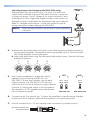
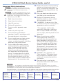
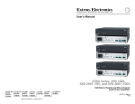
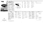
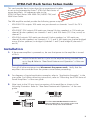
XTRA Full Rack Series Setup Guide
This card provides basic instructions for an experienced installer
T:
or
to set up and operate the Extron® XTRA Full Rack Series of
RTAN
om f
MPO extron.c and
I
.
power amplifiers. All references refer to the
e
d
w
i
u
ww user g
ns.
r to
XTRA Full Rack Series: XPA 2002-70V, 2003C-70V, and
Refe mplete nstructio
o
i
c
n
e
o
th
2004 User Guide.
llati
insta
The XPA amplifier models provide the following power outputs:
•
XPA 2002-70V outputs 200 watts rms per channel on channels 1 and 2 for 70 V
systems.
•
XPA 2003C-70V outputs 200 watts per channel (4-ohm speakers) or 100 watts per
channel (8-ohm speakers) on channels 1 and 2, and 200 watts (70 V line, mono) on
channel 3.
•
XPA 2004 outputs 200 watts per channel (4-ohm speakers) or 100 watts per
channel (8-ohm speakers) on channels 1, 2, 3, and 4, 400 watts per channel bridged
mono (8-ohm speakers) on bridge A (channels 1 and 2) and bridge B (channels 3
and 4).
Installation
1. If the power amplifier is powered on, be sure that power to the amplifier is turned
off first.
NOTE: Adjust the audio level to = prior to the amplifier being powered back
up in Step 4. Refer to “Rear Panel Features and Operation” of the user
guide.
Turn off all other equipment and disconnect the power cords. Verify that the
amplifier is disconnected from the power source before proceeding.
2. For diagrams of typical application examples, refer to “Application Examples” in the
user guide. For further mounting instructions, refer to “Mounting the XTRA Series of
Power Amplifiers” of the user guide.
3. Wire input to the 3.5 mm input connectors of the amplifier, as shown in the
following illustration. Refer to “Rear Panel Features and Operation” of the user
guide.
Tip
Ring
Sleeve
Tip
Sleeve
Unbalanced Input
Left or Right
Balanced Input
" (5 mm) MAX.
The wires must not be tinned: tinned wire
does not hold tight in the captive screws and
can break easily after several bends.
1
XTRA Full Rack Series Setup Guide, cont’d
Selecting inputs for bridging (XPA 2004 only): Bridged
1
2
3
4
output of inputs 1 (Bridge A) and 3 (Bridge B) doubles the
output of those inputs. Refer to "Bridged mode output”
of the user guide for wiring instructions. Wire speakers to
the output connectors of the amplifier using the included 2-pole (XPA 2002-70V
and XPA 2003C-70V) or 4-pole (XPA 2003C-70V and XPA 2004) screw lock plug
2-pole connector wiring:
(BRIDGE A)
70V
(BRIDGE B)
70V
1
3
2
XPA 2003C-70V
XPA 2002-70V
WARNING: Do not short the “+”
and “-” connectors
with each other or
to ground; doing so
will short the outputs
and may damage the
amplifier.
Do not tin the wires!
UT
TP
OU70V
4-pole connector wiring:
8
1
/ 4
2
8
XPA 2003C-70V
BRIDGE A
BRIDGE B
1
3
4
/4
(BRIDGE 8
/4
2
(BRIDGE 8
ONLY)
8
ONLY)
XPA 2004
UT
TP 2
Do not tin the wires!
OU
1
WARNING: Do not short the
“+” and “_”
outputs to each
other. Doing so will
short the outputs
and may damage
the amplifier.
For complete wiring details, refer to “Rear Panel Features and Operation” of the
user guide.
2
BRIDGE
MODE
Selecting outputs for bridge mode (XPA 2004 only):
Bridging takes the signal from input 1 or input 3 or both and
outputs the combined output of 400 watts from the + terminals
of output channels 1 and 2 (Bridge A) or output channels 3 and
4 (Bridge B) or both. Toggle the bridged output mode switch up
(bridged) or down (unbridged) for the appropriate input channel.
Refer to “Bridged mode output” of the user guide for specific
wiring instructions when bridging the XPA 2004.
A
ON
OFF
BRIDGE A
1
2
NOTE: When bridging outputs, the minimum load impedance
is 8 ohms.
8
/ 4
( 8BRIDGE
ONLY )
8 Ohm
4. a. Reconnect all power cords and switch on all other equipment before powering
up the power amplifier. The amplifier must be powered up last. The front panel
LEVEL
LED of the amplifier
should light green.
b. Adjust the audio level using the rear panel adjustment screws. See the following
example illustration.
14
1
2
3
4
12 10 8
12 10 8
12 10 8
12 10 8
18
6 14
4
26
4
2
0
6 14
6
4
2
0
6 14
4
2
0
2
0
HPF
HPF
5. Use a small screwdriver to toggle this switch
between off (no filtering) and 80 Hz. The
XPA 2002-70V has two switches, one for each
output channel. The XPA 2003C-70V has one
switch for the 70V line distribution output channel
(channel 3). Setting the switch to 80 Hz prevents
the saturation of 70V speaker input transformers
by low frequency signals.
CH 2
CH 3
80 Hz 80 Hz
80 Hz
CH 1
OFF
OFF
OFF
XPA 2002-70V
XPA 2003C-70V
6. Connecting pin 2 to ground (pin 1) places the amplifier in standby mode. Standby
mode turns off all outputs, although the amplifier is still receiving power.
7. Use the included 2-pin, 3.5 mm captive screw connector to jumper the pins.
To Contact Closure Port
on Control Device
STANDBY
3
XTRA Full Rack Series Setup Guide, cont’d
10.Protect the power cord from being
Important Safety Instructions
C This symbol is intended to alert the user
of important operating and maintenance (servicing)
instructions in the literature provided with the
equipment.
I
W This symbol is intended to alert the user of
the presence of uninsulated dangerous voltage within
the product’s enclosure that may present a risk of
electric shock. On the product, risk of shock may be
indicated by this symbol:
D
D
walked or pinched particularly at
plugs, convenience receptacle, and
the point where they exit from the
apparatus.
11.Only use attachments/accessories
specified by the manufacturer.
12.Unplug this apparartus during
lightning storms or when unused
for long periods of time.
1. Read these instructions.
2. Keep these instructions.
13."WARNING: To reduce risk of fire
3. Heed all warnings.
or electric shock, do not expose this
apparatus to rain or moisture."
4. Follow all instructions.
5. Do not use this apparatus near
water.
6. Clean only with dry cloth.
7. Do not block any ventilation
openings. Install in accordance with
the manufacturer's instructions.
8. Do not install near any heat sources
such as radiators, heat registers,
stoves, or other apparatus (including
amplifiers) that produce heat.
9. Do not defeat the safety purpose
of the polarized or grounding-type
plug. A polarized plug has two
blades with one wider than the
other. A grounding type plug has
two blades and a third grounding
prong. The wide blade or the third
prong is provided for your safety. If
the provided plug does not fit into
your outlet, consult an electrician for
replacement of the obsolete outlet.
"This apparatus shall not be
exposed to dripping or splashing
and no objects filled with liquids,
such as vases, shall be placed on the
apparatus."
14.Refer all servicing to qualified
service personnel. Servicing is
required when the apparatus has
been damaged in any way, such
as when the power-supply cord or
plug is damaged, liquid has been
spilled or objects have fallen into
the apparatus, the apparatus has
been exposed to rain or moisture,
does not operate normally, or has
been dropped.
15.WARNING: This apparatus is a
Class I product. This product must
be connected to a MAINS socket
outlet with a protective earthing
connection.
16.The mains plug is used as the
disconnect device and shall remain
readily operable.
W
Power sources • This equipment should be operated only from the power source indicated on the product.
This equipment is intended to be used with a main power system with a grounded (neutral) conductor. The third
(grounding) pin is a safety feature, do not attempt to bypass or disable it.
Power disconnection • To remove power from the equipment safely, remove all power cords from the rear of the
equipment, or the desktop power module (if detachable), or from the power source receptacle (wall plug).
Extron USA - West
Headquarters
Extron USA - East
Extron Europe
Extron Asia
Extron Japan
Extron China
Extron Middle East
+800.633.9876
+800.633.9876
+800.3987.6673
+800.7339.8766
+400.833.1568
Inside USA/Canada Only
Inside USA/Canada Only
Inside Europe Only
Inside Asia Only
+81.3.3511.7655
+81.3.3511.7656 FAX
+971.4.2991800
+971.4.2991880 FAX
+1.714.491.1500
+1.714.491.1517 FAX
+1.919.863.1794
+1.919.863.1797 FAX
+31.33.453.4040
+31.33.453.4050 FAX
+65.6383.4400
+65.6383.4664 FAX
4
Inside China Only
+86.21.3760.1568
+86.21.3760.1566 FAX
© 2010 Extron Electronics. All rights reserved. www.extron.com
68-783-50 Rev A
06 10