1
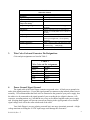
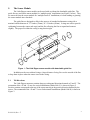
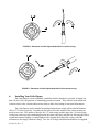
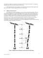
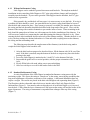
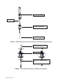
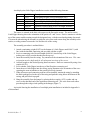
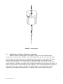
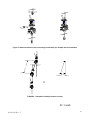
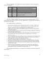
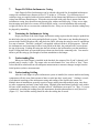
User Manual: Model 906 Little Dipper B-98-1010 Rev. F Serial Number______________________________ ___________________________________________ Bipolar Output (±2.5 volts typical) Unipolar Output (0-5 volts typical) Vertical Orientation Horizontal Orientation 140 Chestnut Street San Francisco, CA 94111 Phone: 415–364–3200 Fax: 415–861–1448 www.geomechanics.com ©2008 Applied Geomechanics Inc. All rights reserved. TABLE OF CONTENTS 1. Introduction .......................................................................................................................................... 1 2. Specifications........................................................................................................................................ 1 3. Wire Color Code and Connector Pin Designations .............................................................................. 2 4. Power Ground/ Signal Ground ............................................................................................................. 2 5. The Sensor Module ............................................................................................................................... 3 5.1 Tilt Directions ................................................................................................................................. 3 6. Installing Your Little Dipper ................................................................................................................ 4 6.1 Multiple Point Installation ............................................................................................................... 5 6.1.1 Without Inclinometer Casing .................................................................................................... 6 6.1.2 Standard Inclinometer Casing ................................................................................................... 6 6.2 Multiple Interval In-Place Inclinometer Installation ....................................................................... 9 7. Proper Fit Within Inclinometer Casing .............................................................................................. 13 8. Tensioning the Inclinometer String .................................................................................................... 13 9. Understanding Bias............................................................................................................................. 13 10. Understanding Settling ..................................................................................................................... 13 11. Recording Tiltmeter Data with External Recorders ......................................................................... 14 12. Converting Voltage Readings to Tilt Angles and Temperatures ...................................................... 14 13. Using the Model 870 Readout Module............................................................................................. 15 13.1 Model 870 Battery Replacement ................................................................................................. 15 14. Warranty and Assistance .................................................................................................................. 15 APPENDIX A - Multiple Point Installation Guide ................................................................................. A1 APPENDIX B - Balanced Wheel Set Installation Guide......................................................................... B1 APPENDIX C - Calibration Certificate ................................................................................................ C1 APPENDIX D - Data Reduction Table ................................................................................................ D1 B-98-1010, Rev. F i 1. Introduction The Model 906 “Little Dipper” Biaxial Clinometer is an economical biaxial inclinometer for measuring ground and slope deformation. The sensing element is an electrolytic tilt transducer, comprised of a glass vial containing a conductive liquid and five internal electrodes. As the sensor tilts, the liquid alternately covers and uncovers opposing electrodes, changing the AC resistance measured along different paths through the sensor. The arrangement of the four outer electrodes in four quadrants enables the electronics to resolve the direction and magnitude of rotation about two orthogonal axes (X and Y). Signal conditioning electronics are built into each Little Dipper, which means each sensor is calibrated with it’s own electronics. The electronics output a high-level DC voltage that varies in direct proportion to rotation. This voltage is referenced to ground and sent down the clinometer cable for recording by the user. Your Little Dipper also measures temperature. The analog temperature signal is referenced to the common ground and has a scale factor of 0.1 °C/mV and an accuracy ±0.75 °C. Your Little Dipper is housed in a rugged, ABS enclosure. It is intended for total submergence with a pressure rating of 75 psi. Little Dippers are available for vertical or horizontal boreholes. By attaching or removing the fins, several Little Dippers can be installed as multiple-point or multiplelength inclinometers measuring casing deflection at the depth of installation. The fins included with your Little Dipper are used for placement and orientation inside a standard inclinometer casing with a diameter of 2.75 inches or greater. The Little Dipper can also be sanded or grouted into a borehole. 2. Specifications General specifications for your Little Dipper are can be found in Table 1. Tabulated calibration data for your clinometer are at the end of this manual in Appendix A, along with plots of the X and Y outputs over their calibrated ranges. B-98-1010, Rev. F 1 TABLE 1 SPECIFICATIONS Two Number of Axes 20 arc seconds (1 part in 10,000) Resolution +/- 12 degrees Angular Range 0.15 second Response Time (Time Constant) Operating and Storage -25ο to +70οC Temperature Range +/- 2.5 volts DC , 0-5 Volts DC (upgrade Output Voltage Range available) Approx. 4 degrees/Volt (see Appendix A) Scale Factor Temperature Sensor Output = 0.1οC/mV, 0mV = 0 οC. ±0.75 οC accuracy 270 ohms, short circuit protected Output Impedance +8 to +24 volts DC at 7mA, 250 mV Power Requirements peak-to-peak ripple max., reverse polarity protected Multi-conductor cable with tinned wire ends Output Connections 1.5 inches (33mm) diameter x 9.25 inches Size & Weight 0.75 lb (0.35 kg) (235mm) long; ABS plastic (body) and Delrin (fins) Materials 3. Wire Color Code and Connector Pin Designations Color and pin assignments are listed in Table 2. TABLE 2 Wire Color and Pin Assignments Function Color Power Red Signal Ground White Power Ground Black X tilt Green Y tilt Blue Temperature Yellow 4. Power Ground/ Signal Ground The signal cable of the Little Dipper contains two ground wires: A black power ground wire and a white signal ground wire. Power and signal ground are common on the internal printed circuit assembly. We recommend that the black wire be connected to the ground of your power supply, that the white wire be connected to the signal ground of your recording device (digital voltmeter, A/D converter, recording station, etc.), but that the two wires not be shorted together at the power supply end. Keeping them separate will prevent current from flowing in the signal ground wire so that the signal voltage level will be the same at both ends of the cable. Your Little Dipper is reverse-polarity protected but is not surge (transient) protected. A highvoltage transient exceeding the 24 VDC input range could damage the electronics. B-98-1010, Rev. F 2 5. The Sensor Module The Little Dipper sensor module can be used with or without the detachable guide fins. The guide fins are used on the sensor module for “multiple point” installations (see Figure 1 below). They are removed from the sensor module for “multiple interval” installations, or when sanding or grouting the sensor module into a borehole. The guide fins are designed to slide in the grooves of standard inclinometer casing with a nominal outside diameter of 2.75 inches (70mm), or 3.34 inches (85mm). O-rings are used to provide cushioning between the sensor end cap(s) and the fins, allowing the fins to expand and contract slightly. The proper fit within the casing is snug but not tight. Figure 1 - The Little Dipper sensor module with detachable guide fins In addition to the two cushion O-rings, a larger diameter O-ring fits over the outside of the fins to keep them in place when the sensor is not in the casing. 5.1 Tilt Directions The Little Dipper measures rotation along two orthogonal directions denoted as X and Y. The orientation of the +X and +Y axes for vertical installations (Model 906-V) is shown in Figure 2. Positive rotation corresponds to the top of the sensor moving in the positive direction denoted by the arrows. The orientation of the +X and +Y axes for horizontal installations (Model 906-H) is shown in Figure 3. B-98-1010, Rev. F 3 FIGURE 2 - Placement of Little Dipper Model 906-V in vertical casing. FIGURE 3 - Placement of Little Dipper Model 906-H in horizontal casing. 6. Installing Your Little Dipper The Little Dipper is most commonly installed in shallow boreholes, generally at depths less than 150 feet (45m) for purposes of monitoring ground movement. They can also been installed in concrete block walls, caissons and cast into concrete slabs for tracking of structural deformation. The Little Dipper can be installed in standard inclinometer casing with an internal diameter (ID) of 2.75 inches or greater. Presently the fins which fit on the outside of the sensor housing are made in two sizes. The smaller of the two fits 2.75 inch casing, and the larger fits 3.34-inch casing. O-rings are used to provide cushioning between the sensor end cap(s) and the fins, allowing the fins to expand and contract slightly, creating slight pressure against the walls of the casing so that the inclinometer fits snugly within the casing. Two sets of O-rings with different thickness are supplied B-98-1010, Rev. F 4 with each Little Dipper for “fine-tuning” the snugness of fit. For maximum stability, it is important that all the guide fins have positive contact with the casing. The maximum number of Little Dippers we recommend for installation within a single cased hole are 10 for the 2.75-inch casing and 20 for the 3.34-inch casing. 6.1 Multiple Point Installation This application uses the Little Dipper to measure rotation at the instrument depth. This type of installation is appropriate for monitoring shoring systems or slurry walls as well as many types of movement, including creep, toppling, and subsidence. The assumption inherent in a multiple point installation is that measuring rotation at multiple points within the casing can adequately reflect the total amount of deformation. This is generally true when the length of casing over which the deformation occurs is greater than the instrument spacing. When most of the movement may be occurring on a discrete shear whose location is uncertain, a multiple interval installation is recommended. A multiple point installation can be used for monitoring movement within a shear zone if the location (depth) of the shear zone is known. L L L d L d = L sin θ θ L Figure 4 - Multiple point inclinometer profiling with the Little Dipper B-98-1010, Rev. F 5 6.1.1 Without Inclinometer Casing Little Dippers can be sanded or grouted into an uncased borehole. The simplest method of installation involves attaching Little Dippers to PVC pipe using radiator clamps, and lowering the assembly into the borehole. If you want to grout the Little Dippers into the borehole, the PVC pipe can be used as a grout tube. If the ground is dry and the hole will stay open, it is not necessary to case the hole. If caving is a problem, the hole should be cased. An open-ended steel or plastic casing should then be lowered into the hole and cemented in place. If no cement or concrete is available, the annular space between the casing and the hole boundary should be backfilled with clean sand or fine gravel. Next, seal the bottom of the casing with cement or bentonite to prevent the influx of water. Water remaining in the hole should be pumped out or blown out with compressed air before installation of the tiltmeter. You will have more control over compacting the sand and orienting the tiltmeter if the hole is dry. Water entering the hole after installation does not adversely affect tiltmeter stability. Whether the hole is wet or dry, the best readings are obtained when there is a firm and stable coupling between the tiltmeter, the casing and the surrounding earth. The following steps describe the emplacement of the tiltmeter(s) in the hole using sand to couple the Little Dippers to the borehole wall: 1. After the hole has been prepared as described above, fill the bottom with 10-20 cm of fine sand. If the hole is uncased, tamp the bottom of the hole to compact any loose dirt before pouring in the sand. 2. Lower the Little Dipper(s) attached to the ½-inch PVC to the bottom of the hole. 3. Suspended the guide rod in a vertical position, with the proper orientation of the X- and YAxes. 4. Slowly fill the hole with sand, taking care to prevent bridging. 5. Allow several days to a week for the sand to settle in the hole. 6.1.2 Standard Inclinometer Casing A vertical installation of the Little Dipper in standard inclinometer casing starts with the tensioning weight. This forces the string to “stretch-out” in the casing, removing the possibility that long-term adjustments will produce erroneous or false readings. A horizontal installation does not require a weight. The sensors are placed in the hole with fiberglass rods separating them (Figure 5). The fiberglass rods have threaded ends which screw into the ends of the Little Dipper In-Place Inclinometers (Figure 5). Care must be taken to align the axis of each Little Dipper as it is lowered into the hole. Cables from the lower clinometers are fed between the casing wall and the bodies of the upper clinometers. The string of instruments is suspended from a hanger at the top of the casing (Figure 7). B-98-1010, Rev. F 6 86801 Connecting Rod 70304 Cable 906-V Little Dipper (with guide fins attached) 86801 Connecting Rod FIGURE 5 - Vertical placement for point measurement in standard inclinometer casing 906-V Little Dipper (with guide fins attached) Threaded rod 01470 Tensioning Weight (Allow 2 ft. min. beneath bottom sensor) FIGURE 6 - Connecting rod assembly for multiple point installation B-98-1010, Rev. F 7 A multiple-point Little Dipper installation consists of the following elements: Item 1 2 3 4 5 6 Model No. 01470 906-V 86801-01 01471 86801-02 86802 Description Tensioning Weight (vertical installation only) Little Dipper sensor assembly (with fins) Connecting Rod (10ft or 3m length standard) Optional Hex-Coupler for adding extension rods Optional Extension Rod (10ft or 3m length standard) Hanger for Model 906-V The sensor is oriented in the hole with respect to the fins on the sensor. The sticker on the Little Dipper housing shows the orientation of the positive X- and Y-axes. Positive rotation is with the top of the sensor module rotating toward the designated axes, with the arrowhead pointing downward. Care must be taken during the assembly to guide the wires from each sensor along the assembly to the surface, avoiding contact between the wire and the side of the casing. The assembly procedure is outlined below: 1. Attach a tensioning weight (01470) to the bottom of a Little Dipper model 906-V (with fins) with the threaded connecting rod provided with the weight. 2. Screw a connecting rod of desired length (86801-01) into the top of the Little Dipper, making sure to fully seat the threads into the top cap. 3. Insert the assembly into the casing. Pay attention to the orientation of the axes. This same orientation must be duplicated for all subsequent insertions of the sensor. 4. Add rod lengths to the desired spacing between sensors. Rods are connected by using a hex coupler (01471). 5. Screw another Little Dipper into the top of the fiberglass connecting rod. 6. Insert the next Little Dipper into the casing, paying attention to the orientation of the axes repeating the same orientation as the sensors previously inserted. 7. When all sensors and connecting rods have been installed, tension the string by attaching the black push/pull rod to the top of the string and push the string below the bottom of the casing, and pull it back up again. 8. Hang the assembly from the hanger by placing the hex coupler (1471) washer and cap screw on the threaded end of the uppermost connecting rod. The wires from each sensor pass through the wedge-sized opening in the hanger (Figure 7). A pictorial showing the installation of a multiple point installation is included in Appendix A of this manual. B-98-1010, Rev. F 8 FIGURE 7 - Casing hanger 6.2 Multiple Interval In-Place Inclinometer Installation With the optional variable length kit, the length of casing over which angular rotation measurements are made can be infinitely varied. In this application, the fins are removed from the sensor module, and a balanced wheel set is attached to the bottom of the sensor module. Fiberglass rods are attached to the top of the sensor module to extend the length over which the sensor is measuring rotation (Figure 8). A weight is placed at the bottom of the string of sensors to keep the system in tension. This allows fiberglass to be used instead of stainless steel (as long as the string is in tension, a string could be used to attach the sensors together). The u-joint assemblies at the upper end of the wheel set act as pivot points, allowing each gauge length to move independently without transferring any bending to adjacent lengths. A schematic of the system is shown in Figure 9. B-98-1010, Rev. F 9 Figure 8 - Balanced wheel set and connecting rod assembly for multiple interval installation θ L FIGURE 9 - Schematic of multiple-interval concept D = Lsinθ B-98-1010, Rev. F 10 86819 Balanced wheel set with u-joint (with guide fins attached) 86801-02 Extension Rod 01471 Hex Coupler 70304 Cable 86801-01 Connecting Rod 906-V Little Dipper (without guide fins) 86819 Balanced wheel set with u-joint Threaded rod 01470 Tensioning Weight (Allow 2 ft. min. beneath bottom sensor) FIGURE 10 - Exploded view of multiple-interval components B-98-1010, Rev. F 11 The basic components of the multiple interval in-place inclinometer system are listed below and shown in Figure 10. Item 1 2 3 4 5 6 Model No. 01470 86819 906-V CTC-3,5,10 CTC CTE-3,5,10 7 86819 Description Tensioning Weight (vertical installation only) Balanced wheel set Little Dipper sensor assembly without fins Connecting rod in 3-, 5- or 10-foot lengths (standard) Optional coupler for adding extension rods Optional extension in 3-,5-,10-foot lengths. Added by using CTC Coupler Balanced wheel set The sensor is oriented in the hole with respect to the wheels on the balanced wheel set. It is useful to attach all the wheel set (86819) to the Little Dippers (906-V) with guide fine removed prior to the installation in the casing. The assembly procedure is outlined below: 1. Attach the top of the balanced wheel set to the bottom of the Little Dipper (without fins) with a 6/32 - 1-3/8 inch cap screw. Align the thru-holes in the top of the universal joint with those in the bottom of the sensor to align the Y axis with the wheels. 2. Attach a string tensioner (01470) to the bottom of a wheel set (86819)using the threaded connecting rod supplied. 3. Screw the connecting rod (86801) into the top of the Little Dipper, making sure to fully seat the threaded adapter into the top cap. 4. Insert the assembly into the inclinometer casing. Pay attention to the orientation of X- and Y-axes on the sensor. This same orientation must be duplicated for all subsequent insertions of sensors. 5. Screw connecting rod into bottom of the next wheel set (attached to the Little Dipper) in the sequence. Rotate the sensor until the wheels are aligned with slotted casing, and sensor axes are in the same location as that on the previous sensor. 6. Install additional gauge lengths by repeating steps 3-5 as necessary. 7. Care must be taken to guide the wires from each sensor along the assembly to the surface. 8. When all sensors and connecting rods have been installed, tension the string by attaching the push/pull rod to the top of the string and push the string below the bottom of the casing, and pull it back up again. 9. Hang the assembly from the hanger by placing the hex coupler (1471) washer and cap screw on the threaded end of the uppermost connecting rod. The wires from each sensor pass through the wedge-sized opening in the hanger (Figure 7). A pictorial showing the installation of a multiple interval installation is included in Appendix B of this manual. B-98-1010, Rev. F 12 7. Proper Fit Within Inclinometer Casing Little Dipper In-Place Inclinometers can be ordered with guide fins for standard inclinometer casing with a nominal outer diameter (OD) of 2.75-inches or 3.34-inches. Two different sizes of cushion o-rings are supplied with each sensor module for the dimensional differences of inclinometer casing from different manufacturers. When the sensor module with guide fins is inserted into the inclinometer casing, they should bet snug but not tight, with no noticeable play. If they are too tight, then inserting more than a few sensors will be difficult, and in a vertical installation the tensioning weight will not be able to overcome the combined friction. If they are too loose, then the readings may be plagued by instability. 8. Tensioning the Inclinometer String Proper placement of the Little Dipper inclinometer string requires that the string be pushed into the hole below the top of the casing and pulled back up again. This removes any bending that may be present in the flexible fiberglass rods, and slacks the cables, allowing the string to come to equilibrium in a state of tension. The black “push/pull” rod supplied with each order is for this purpose. After all the inclinometers and connecting rod have been placed in the hole, the push/pull rod is screwed onto the top of the string. Pushing the string into the hole advances the inclinometers past the installation depth. Pulling them back up repositions them without any bend in the connecting rods. Care must be taken to pull the string up just enough to facilitate attachment to the hanger. 9. Understanding Bias When your Little Dipper is installed in the borehole, the outputs of the X and Y channels will probably not be exactly 0 volts. The output value on each channel is its "zero offset' or "bias." These values should be subtracted from all subsequent measurements to measure changes in angle from the initial position (relative measurements). 10. Understanding Settling After the Little Dipper in-place inclinometer system is installed, the sensors modules and string components will take some finite amount of time to settle into their “steady state.” Settling is a result of mechanical stretching of the inclinometer string and settling of the liquid in the sensor vial. Multiple interval installations generally require a longer settling time than multiple point, since there are more components and more joints in the string. Multiple point installations generally settle within 48 hours of the installation, whereas “multiple interval” installations can require 5 to 7 days. If you are continuously recording the readings from the instruments, then this phenomenon is easily observed (Figure 11). Your baseline reading should be after the settling has occurred. B-98-1010, Rev. F 13 Fluid settling Mechanical settling FIGURE 11 - Different magnitudes of initial settling of in-place inclinometers If you are taking manual readings, then to be safe your baseline reading should not be taken for a week after installation (readings can be taken thin the first week to verify operation). 11. Recording Tiltmeter Data with External Recorders The low-impedance analog output of Little Dipper is readily measured by a variety of external devices, including digital voltmeters, oscilloscopes, strip-chart recorders, and analog-to-digital converters. Refer to Table 2 for the connector pin information or cable color coding you'll need to connect your tiltmeter to your recording device. 12. Converting Voltage Readings to Tilt Angles and Temperatures The voltage outputs of the Little Dipper are quickly converted to tilt angles by using the scale factors or the polynomials in the Calibration Certificate at the end of this manual. To use the scale factor, simply multiply the voltage reading by the scale factor. For example, if the scale factor of the X channel is 4.06 degrees/volt, and the X output is +2.000 volts, the tilt angle is +8.12 degrees (including the bias). To obtain tilt angle from the polynomial, substitute your voltage reading for the variable V and use the listed polynomial fit coefficients. Again, the result includes the bias. Using the polynomial eliminates most of the nonlinearity and gives the most accurate results. To obtain temperature in degrees Celsius, simply multiply the voltage reading on the temperature channel by 100 °C/Volt. Appendix B of this manual contains a form to help document and convert readings to tilt angles. B-98-1010, Rev. F 14 13. Using the Model 870 Readout Module The Model 870 Readout Module may be used to power your Little Dipper (units with bipolar output only) and switch the X and Y channel outputs to a digital multimeter for display. If your Little Dipper was shipped with a Model 870 it will have a 6-pin connector on the end of its cable. Skip this section if you did not purchase a Model 870. The Model 870 Readout Module is designed for use with any hand-held multimeter containing banana plug sockets with standard 0.75-inch center-to-center spacing. To use the Model 870, first plug it into your clinometer cable via the 6-pin connector. Then plug it into your multimeter via the banana jacks (red to red, black to black). Set the multimeter to its DC Volts setting and turn it on. Turn the XOFF-Y switch on the Model 870 to the X or Y position (this powers the clinometer). Now, depress the BATTERY CHECK button. If the voltage displayed on the multimeter is below 8 volts, replace the battery inside the Model 870 with a new one as described in the next section. You are now ready to read your Little Dipper. Turn the toggle switch to X or Y and read the output voltage on the multimeter display (the multimeter must be in its DC Volts setting). The temperature channel cannot be read using the Model 870. 13.1 Model 870 Battery Replacement If the voltage level of the Model 870 Readout Module battery drops below 8 volts, it should be replaced. The battery is a standard 9-volt radio battery, available in most supermarkets and hardware stores. To replace the battery: 1. Remove the four metal screws from the back panel. Carefully separate the back panel from the front portion of the Readout Module. Do not twist or pull the internal wiring. 2. Replace the old battery with a fresh new battery. 3. Replace the back panel. 14. Warranty and Assistance Your Model 906 Little Dipper is warranted against defects in materials and workmanship for 90 days from the date of delivery. AGI will repair or replace (at its option) goods that prove to be defective during the warranty period provided that they are returned prepaid to AGI and: (a) that the goods were used at all times for the purpose for which they were designed and in accordance with any instructions given by AGI in respect of them, (b) that notice is received by AGI within 30 days of the defects becoming apparent, and (c) that return authorization is received from AGI prior to the goods being sent back. Should goods be damaged in transit to the Purchaser, AGI will accept no liability unless the Purchaser can show that such damage arose solely from AGI's failure to pack the goods properly for shipment. Software products are warranted to perform substantially in accordance with their documentation for 90 days following your receipt of the software. AGI and its suppliers do not and cannot warrant the performance or results you may obtain by using the software or its documentation. In respect of goods or parts thereof manufactured by others and resold by AGI, AGI will pass on to the customer the benefit of any guarantee or warranty received by AGI from the original manufacturer insofar as such guarantee or warranty is assignable. B-98-1010, Rev. F 15 ANY OTHER CONDITIONS OR WARRANTIES WHETHER EXPRESS OR IMPLIED BY STATUTE OR OTHERWISE ARE EXCLUDED. THE REMEDIES PROVIDED HEREIN ARE THE BUYER'S SOLE AND EXCLUSIVE REMEDIES. APPLIED GEOMECHANICS INC. SHALL NOT BE LIABLE FOR ANY DIRECT, INDIRECT, SPECIAL, INCIDENTAL OR CONSEQUENTIAL DAMAGES, INCLUDING LOST PROFITS OR LOST SAVINGS, WHETHER BASED ON CONTRACT, TORT, OR ANY OTHER LEGAL THEORY. THIS WARRANTY EXTENDS ONLY TO THE ORIGINAL PURCHASER AND IS EXPRESSLY IN LIEU OF ALL OTHER WARRANTIES, WHETHER OF MERCHANTABILITY OR FITNESS FOR ANY PARTICULAR USE, AND OF ALL OTHER OBLIGATIONS AND LIABILITIES OF ANY KIND AND CHARACTER. THERE ARE NO WARRANTIES WHICH EXTEND BEYOND THE DESCRIPTION ON THE FACE HEREOF. (a) AGI's liability arising out of the sale of its goods is expressly limited to the repair and/or replacement of defective parts or the cost of such repair and/or replacement. (b) If software does not perform substantially in accordance with the documentation, the entire and exclusive liability and remedy shall be limited to either, at AGI’s option, the replacement of the software or the refund of the license fee you paid for the software. (c) Liability for any other form of loss or damage is hereby expressly excluded. (d) Customer shall indemnify AGI against any third party claim arising out of the use of goods and/or services supplied by AGI, including any claim arising directly or indirectly out of alleged negligence on the part of AGI, its employees, servants, representatives or agents. B-98-1010, Rev. F 16 Appendix A Multiple Point Installation Guide “Multiple Point” Installation of the Little Dipper 1. Equipment ready for installation 2. Labeling cable end 3. Guide fins removed for cushioning Oring replacement 4. Cushion O-ring used to make guide fins fit snugly in casing 5. Guide fin assembly complete with cushion O-ring and circumferential 6. Little Dipper with guide fins attached Multiple Point Appendix A A1 “Multiple Point” Installation of the Little Dipper 7. Attaching tensioning weight to lowermost Little Dipper 8. Aligning guide fins with casing grooves 9. Lowering Little Dipper and rod assembly 10. Attaching cable to rod with cable ties 11. Using hanger to suspend string during installation 12. Screwing connecting rod into bottom of Little Dipper Multiple Point Appendix A A2 “Multiple Point” Installation of the Little Dipper 13. Multiple cables led up between guide fins on Little Dipper 16. The string is pushed into the hole for the length of the push/pull rod… Multiple Point Appendix A 14. Attaching multiple cables to rod with cable ties 17. Then pulled back up 15. Push/Pull rod attached to top of inclinometer string 18. Installation complete - string hung from casing hanger and cables fed through opening A3 Appendix B Multiple Interval Installation Guide “Multiple Interval” Installation of the Little Dipper 1. Little Dipper with balanced wheel set attached - ready for installation 2. Inserting wheel set into bottom of Little Dipper sensor module 3. Inserting 6/32 cap screw into cross-hole. 4. Attached wheel set is now aligned with Y-axis. 5. Screwing weight on to lower-most Little Dipper with wheel set. 6. Lowermost Little Dipper/balanced wheel set/tensioning weight ready for installation Balanced Wheel Set Appendix B B1 “Multiple Interval” Installation of the Little Dipper 7. Lowering assembly into casing. 8. Compressing wheels to fit into casing 9. Close-up of wheels being compressed 10. Attaching cable to rod with cable ties 11. Using hanger to hold string during installation 12. Using cable ties to attach cables to connection rod Balanced Wheel Set Appendix B B2 “Multiple Interval” Installation of the Little Dipper 13. Push/Pull rod attached to top of inclinometer string 14. The String is pushed into the hole for the length of the push/pull rod 15. Then pulled back up 16. Installation complete - string hung from casing hanger and cables fed through opening Balanced Wheel Set Appendix B B3 Appendix C Calibration Certificate Appendix D Data Reduction Table