1
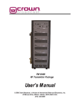
RF Broadcast Appliance Family
User Manual
Applicable Models:
RFBA-1 – AM/FM/NOAA Weather Band Triple Receiver and FM MPX Translator
RFBA-1MA – AM/FM/NOAA Weather Band Triple Receiver, FM MPX Translator, and AM/FM/NOAA
Weather Band Triple Modulation Analyzer
Document Revision History:
V0.9
27APR2012
CHT
Preliminary Release
V1.03
30APR2012
CHT
Release
V1.04
25JUN2012
CHT
Update for Public Service Band
RFBA User Manual
Chrisso Technologies, LLC
Page 1
Table of Contents
Table of Figures ............................................................................................................................................. 3
Getting Started.............................................................................................................................................. 4
Model Numbers ............................................................................................................................................ 5
Installation and Configurations ..................................................................................................................... 5
Triple Tuner for EAS/CAP Reception ......................................................................................................... 5
Triple Tuner Modulation Analyzer ............................................................................................................ 6
Standalone FM Translator with RDS Encoding ......................................................................................... 6
Stand-alone Automatic Stereo Separation (SASS) ................................................................................ 6
Mixed Combination of Other Configurations ........................................................................................... 7
Broadcast Appliance System Overview......................................................................................................... 7
Broadcast Appliance Functionality ........................................................................................................... 7
Broadcast Appliance Block Diagram ............................................................................................................. 7
Broadcast Appliance Front Panel .................................................................................................................. 8
User Interface ........................................................................................................................................... 8
Tuner Setup Menu ................................................................................................................................ 9
Tuner Monitor Menu .......................................................................................................................... 12
MPX Setup Menu ................................................................................................................................ 15
Network Setup Menu .......................................................................................................................... 18
System Setup Menu: ........................................................................................................................... 19
Front Panel Lock Out ........................................................................................................................... 21
Broadcast Appliance Remote Control ......................................................................................................... 21
User Interface ......................................................................................................................................... 21
Appliance Home ...................................................................................................................................... 21
Receiver Status........................................................................................................................................ 22
Modulation Analyzer............................................................................................................................... 22
Device Setup ........................................................................................................................................... 23
Contact Info......................................................................................................................................... 27
Product Specifications................................................................................................................................. 27
Software Updates ....................................................................................................................................... 28
USB flash drive requirements ............................................................................................................. 29
FCC / IC Compliance .................................................................................................................................... 29
RFBA User Manual
Chrisso Technologies, LLC
Page 2
Class A Product: .................................................................................................................................. 29
Class B Product:................................................................................................................................... 30
Contact Information.................................................................................................................................... 30
Chrisso Technologies............................................................................................................................... 30
Crown Broadcast ..................................................................................................................................... 30
Sales .................................................................................................................................................... 30
Service ................................................................................................................................................. 31
Table of Figures
Figure 1 - Front View ..................................................................................................................................... 4
Figure 2 - Rear Views .................................................................................................................................... 4
Figure 3 - Phoenix 20-Pin photo (The RFBA uses the 16-pin version of this connector) .............................. 4
Figure 4 - Pin-out........................................................................................................................................... 5
Figure 5 - Block Diagram ............................................................................................................................... 8
Figure 6 - Main Menu.................................................................................................................................... 9
Figure 7 - Navigation Menu Overview .......................................................................................................... 9
Figure 8 - Tuner Setup Menu ...................................................................................................................... 10
Figure 9 - Audio Level Conversions ............................................................................................................. 12
Figure 10 - Tuner Monitor Menu ................................................................................................................ 13
Figure 11 - MPX Setup Menu ...................................................................................................................... 16
Figure 12 - Network Setup Menu................................................................................................................ 18
Figure 13 - System Menu ............................................................................................................................ 19
Figure 14 - Relay Codes ............................................................................................................................... 20
Figure 15 – Web server Navigation Menu .................................................................................................. 21
Figure 16 - Appliance Home ........................................................................................................................ 22
Figure 17 - Receiver Status.......................................................................................................................... 22
Figure 18 - Modulation Analyzer................................................................................................................. 23
Figure 19 - Device Setup -> Receivers ......................................................................................................... 24
Figure 20 - Device Setup -> MPX Output .................................................................................................... 25
Figure 21 - Device Setup -> Alerts ............................................................................................................... 25
Figure 22 - Device Setup -> Network -> IPV4 .............................................................................................. 26
Figure 23 - Device Setup -> Network -> SMTP ............................................................................................ 26
Figure 24 - Device Setup -> System............................................................................................................. 27
Figure 25 - Contact Info .............................................................................................................................. 27
Figure 26 - Specifications ............................................................................................................................ 28
RFBA User Manual
Chrisso Technologies, LLC
Page 3
Getting Started
The front panel of your RFBA family of Broadcast Appliances has a 40x2 character LCD display and a
navigation style button that are shown in Figure 1. The user is able to adjust most of the settings of the
RFBA unit by navigating through the display’s menu with the front panel buttons. Some of the advanced
features are only available via the Ethernet connection.
The rear of the RFBA is shown in Figure 2. The RFBA includes communication connections for Ethernet
and USB, BNC connectors for each tuner input, and one BNC connector for an FM MPX output. The
Phoenix-style connector provides analog audio output from each tuner and a relay output for
configurable alerts. The power jack is used to power the RFBA unit via the included power supply at
12Volts, 1 Amp.
Figure 1 - Front View
Figure 2 - Rear Views
The Phoenix connector mating part number is “FMCD 1.5/8-ST-3.5” and the order number is 1738869.
The figure below shows the 20-pin version of the connector for the RFBA. One mating connector is
provided with the purchase of each RFBA.
Figure 3 - Phoenix 20-Pin photo (The RFBA uses the 16-pin version of this connector)
The pin-out for the RFBA is shown in Figure 4 - Pin-out. The first pin is located closest to the power
supply connector, and is numbered right to left when viewed from the rear of the product. A silkscreen
is also provided on the rear of the unit for quick reference. Connections to the connector are made by
RFBA User Manual
Chrisso Technologies, LLC
Page 4
using a small screwdriver to push in on the orange portion of the connector while inserting your stripped
cable into the corresponding hole.
Top Row
Top #1
Top #2
Top #3
Top #4
Top #5
Top #6
Top #7
Top #8
Description
Tuner 3- Left - / Relay-P1
Ground
Tuner 3- Left
Tuner 2- Left Tuner 2- Left +
Ground
Tuner 1- Left Tuner 1- Left +
Description
Tuner 3- Right - / Relay-P2
Reserved
Tuner 3- Right +
Tuner 2- Right Tuner 2- Right +
Ground
Tuner 1- Right Tuner 1- Right +
Bottom Row
Bottom #1
Bottom #2
Bottom #3
Bottom #4
Bottom #5
Bottom #6
Bottom #7
Bottom #8
Figure 4 - Pin-out
Model Numbers
Currently, there are two models in the RFBA family available: The RFBA-1 and the RFBA-1MA. Both units
will be labeled as “RFBA-1” on the front panel
The RFBA-1MA contains every feature of the RFBA-1, but also adds the ability to operate as a highly
accurate DSP-Based Triple Tuner Modulation Analyzer. Every RFBA-1 unit can be upgraded to be an
RFBA-1MA via a user-installable software key. If you are interested in upgrading your RFBA-1 unit to the
full capabilities of the RFBA-1MA, please contact Crown Broadcast for sales information.
Installation and Configurations
Your RFBA is versatile and designed to handle many user configurations. The typical configurations for
the RFBA are: Triple Tuner for EAS/CAP, Triple Tuner Modulation Analyzer, Standalone FM Translator
with RDS Encoding, or a Mixed Combination of Other Configurations.
Triple Tuner for EAS/CAP Reception
This all-in-one product allows the user to monitor three separate broadcasts while outputting the audio
to a stand-alone EAS/CAP decoder unit. By separating the tuners from the EAS/CAP decoder, the user
can be assured that the sensitivity of the tuners is not compromised by the harsh EMC noise that is
typically seen in the PC-based EAS/CAP decoder units. In this configuration, the audio signals from the
Phoenix connector may be connected directly to the EAS/CAP decoder unit. The audio level for each
tuner may be digitally adjusted to meet the voltage requirements of your particular EAS/CAP decoder.
The RFBA includes capability for Hi-Jack Avoidance and Squelch functions; in this configuration, users
will typically disable these features. The Hi-Jack and Squelch functions can be adjusted via the front
panel setup menus or via the Ethernet connection.
RFBA User Manual
Chrisso Technologies, LLC
Page 5
Triple Tuner Modulation Analyzer
The RFBA is capable of monitoring over 20 FM signal parameters as well as RDS data for each tuner
simultaneously. The end user may wish to monitor several of their own stations to assure proper
functionality or they may wish to monitor adjacent channels that sometimes over-modulate. The RFBA
can also be controlled via the Ethernet connection, allowing a remote user to switch between stations
that are being monitored. For operation in this configuration, the only connections required are the RF
antennas and, if remote monitoring is desired, Ethernet. All of the parameters are available via the
display menu or via the Ethernet connection. Note: the modulation analyzer feature is only available on
the RFBA-1MA or as an upgrade to the RFBA-1. All units are capable of performing modulation analyzer
functionality. If your RFBA does not include this function, please contact Crown Broadcast for sales
information.
Standalone FM Translator with RDS Encoding
The RFBA uses a Digital Signal Processor, or DSP, to reconstruct an FM Stereo Composite Signal. In
addition to the typical composite signal, the RFBA can also add RDS data to the composite signal. The
audio source for this configuration is only available from the main tuner (Tuner #1). Tuner #2 and Tuner
#3 do not include capability for composite signal regeneration, but can still be used for signal reception
or analyzing.
The FM Stereo Composite Signal is always available from Tuner #1. In contrast to older translator
designs, the RFBA does not simply pass through a down-converted FM multiplex. Instead, the audio and
RDS data are recovered using world-class automotive-grade reception algorithms customized by Chrisso
Technologies for translator purposes. A new FM multiplex with optional RDS data is then created
digitally. The composite output signal is available on the BNC connector on the rear of the product, and
can be fed to the composite input of your RF modulator/transmitter. The user can digitally adjust the
MPX output level, pilot percentage, RDS modulation level, and many RDS parameters. Your RFBA will
automatically adjust the audio portions of the FM Multiplex to account for user adjustments of the Pilot
level and of the RDS level, ensuring strict adherence to the composite level specifications of the FCC.
The user can program many of the RDS parameters to be passed through from the received signal or to
be user defined, allowing for certain data to be unique to your translator location. Program
Identification (PID) is an example of an RDS parameter that the end user may wish to program
differently, while leaving Program Service Name (PSName) and other fields unmodified.
Stand-alone Automatic Stereo Separation (SASS)
The FM translator also includes a new function to align the composite output with a specific RF
modulator. Many RF modulators include a filter on the MPX input. This filter can cause a small shift in
the L-R component of the composite signal and will degrade the maximum stereo separation. The RFBA
includes an alignment routine where the RFBA can adjust the L-R for your specific RF modulator thus
optimizing the maximum separation. Please see the alignment section of this manual for further details.
RFBA User Manual
Chrisso Technologies, LLC
Page 6
Mixed Combination of Other Configurations
The RFBA is capable of performing many of the above configurations concurrently. Tuner #1 is always
able to receive a broadcast station and output audio. It is also always able to reconstruct an FM
composite signal from the station received. If the modulation analyzer option is installed, it can also do
a full analysis of the signal received on Tuner #1.
Broadcast Appliance System Overview
The RF Broadcast Appliance (RFBA) has been designed to perform multiple functions. The RFBA includes
three independent automotive grade DSP based receivers. Each receiver is capable of receiving AM, FM,
NOAA Weather band or Public Service frequencies. This makes the RFBA desirable for meeting the
broadcasters EAS needs of monitoring of multiple stations. The RFBA also incorporates a DSP based FM
composite generator that can be used for FM translators. The FM composite generator has additional
functionality to add RDS capability to your translated signal, acting in a RDS pass thru mode or a user
programmable mode. The RFBA can also be used as a triple tuner modulation analyzer and RDS
decoder. Band and frequency selection is performed by front panel user control or remote Ethernet
control.
Broadcast Appliance Functionality
The onboard AM/FM receiver utilizes a Digital Signal Processor (DSP) that incorporates advanced
algorithms to provide world-class receiver performance. Tuner parameters have been optimized by
experts in AM/FM reception to provide the best overall performance for this specific product,
eliminating the need for broadcasters to make adjustments. The receiver is capable of tuning:
1)
2)
3)
4)
5)
FM frequencies from 76.00 – 108.00 MHz in steps of 0.05 MHz (50 kHz)
AM frequencies from 520 – 1710 kHz in 10 kHz increments
AM frequencies from 531 – 1629 kHz in 9 kHz increments
All NOAA weather band channels from 162.400 – 162.550 MHz (Channels 1 – 7)
Public Service band from 144.000 – 175.000 MHz in 5 kHz increments
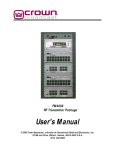
Broadcast Appliance Block Diagram
A high level block diagram of the RFBA is shown in Figure 5. As described previously, this product
contains three independent tuners. Each tuner is capable of receiving AM, FM, NOAA Weather band or
Public Service band. Each tuner has its own BNC RF connector. The right and left audio signals for each
tuner are available as differential outputs on the supplied Phoenix connector. The audio outputs of
tuner #1 are also used by the onboard DSP to generate a FM composite signal that can be used for
translators. The onboard DSP also uses an RDS encoder so the user can add RDS information to the
translator output. The FM composite output is available via a BNC connector on the rear of the product.
Tuner #3 has an option to have a differential or single-ended audio output for the right and left
channels. In the single-ended mode the negative outputs are used as connections to an internal relay.
The relay can be programmed via the display or Ethernet to open or close based on certain events, such
RFBA User Manual
Chrisso Technologies, LLC
Page 7
as squelch or Hi-Jack. The default configuration for Tuner #3 is single ended audio with the internal
relay.
Left+
LeftTUNER 1
Right+
BNC
TUNER#1
Right-
RDS
Encoder
Audio
DSP
BNC
Composite Out
Left+
LeftTUNER 2
Right+
BNC
TUNER#2
Right-
Left+
LeftTUNER 3
Right+
BNC
TUNER#3
RightRelay
USB
Micro
Ethernet
40 x 2 LCD Display
Button
Figure 5 - Block Diagram
Broadcast Appliance Front Panel
User Interface
The RFBA includes a 2 x 40 character LCD and a navigation style button that allows the user to adjust all
settings and monitor all available parameters. The navigation control has up, down, left, right, and enter
buttons that allow the user to adjust most parameters. Some of the more advanced features are
available via the Ethernet interface. The display incorporates arrows to assist the user during menu
RFBA User Manual
Chrisso Technologies, LLC
Page 8
navigation. Upon product initialization the RFBA will display the frequency and RSSI level of all three
tuners, see Figure 6. The RFBA will also default to this main screen after one minute of user inactivity.
9 8 . 1 MH z
S t
R S S I ██████▎
1 0 8 0 k Hz
R S S I ██████▎
1 6 2 . 4 7 5 MH z
R S S I ██████▎
Figure 6 - Main Menu
The overall menu navigation map is shown below:
Main
Tuner 1
Setup
Tuner 1
Monitor
Tuner 2
Setup
Tuner 2
Monitor
Tuner 3
Setup
Tuner 3
Monitor
MPX Setup
Network
Setup
System
Setup
Band
RSSI dBuV
Band
RSSI dBuV
Band
RSSI dBuV
MPX Level
IP
Model
Number
Frequency
RSSI bar
graph
Frequency
RSSI bar
graph
Frequency
RSSI bar
graph
Pilot Level
SUBNET
Serial
Number
GATEWAY
Firmware
version
MAC
Region
RDS
Frequency #2
Auto Squelch
Squelch Level
RSSI Alert
De Emphasis
Main Meter
•
•
•
•
•
•
•
•
•
•
•
•
Modulation
Analyzer
•
•
•
•
•
•
•
•
PPM
threshold
PID
PSNAME
PTY
PTYN
UTC Time
UTC Offset
Local Time
Local Date
TP
TA
MS
DI
•
•
•
•
•
•
Pilot Level
RDS Level
SCA 67 kHz
SCA 92 kHz
Peaks/Minute
Modulation
Deviation
Positvie
Deviation
Negative
Audio Left
Audio Right
Audio L+R
Audio L-R
AM Noise
Multipath
Frequency #2
Auto Squelch
Squelch Level
RSSI Alert
De Emphasis
Main Meter
RDS
RDS Settings
•
•
•
•
•
•
•
•
•
•
•
•
•
•
•
•
•
Modulation
Analyzer
•
•
•
•
•
•
•
•
PPM
threshold
PPM Holdoff
PPM Holdoff
PPM Holdoff
Hi-jack
Avoidance
Hi-jack
Avoidance
Hi-jack
Avoidance
Hi-jack PID
Hi-jack PID
Hi-jack PID
RX PID
RX PID
RX PID
Mono/
Stereo
Mono/
Stereo
Mono/
Stereo
Bandwidth
Bandwidth
Bandwidth
Audio Level
Audio Level
Audio Level
PID
PSNAME
PTY
PTYN
UTC Time
UTC Offset
Local Time
Local Date
TP
TA
MS
DI
•
•
•
•
•
•
Pilot Level
RDS Level
SCA 67 kHz
SCA 92 kHz
Peaks/Minute
Modulation
Deviation
Positvie
Deviation
Negative
Audio Left
Audio Right
Audio L+R
Audio L-R
AM Noise
Multipath
•
•
•
•
•
•
•
•
•
•
•
•
•
RDS State
RDS Level
PID SOURCE
USER PID
PSNAME
SOURCE
USER
PSNAME
PTY SOURCE
USER PTY
TP SOURCE
USER TP
TA SOURCE
USER TA
MS SOURCE
USER MS
DI SOURCE
USER DI
CT SOURCE
RT SOURCE
Software
reset
Restore
Factory
Defaults
Relay
SASS
Aligment
Screen
Timeout
SASS
Separation
Modulation
Analyzer Key
Figure 7 - Navigation Menu Overview
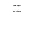
Tuner Setup Menu
Each tuner has a separate menu and can be controlled independently. The menu structure for all tuners
are identical thus the following descriptions is relevant for all three tuners. A description of each of the
setup features is detailed below:
RFBA User Manual
Chrisso Technologies, LLC
Page 9
R X 1 :
S E T UP
R S S I : 5 5 d B µ V
→B A
F R
F R
A U
S Q
R S
DE
MA
P P
P P
H I
H I
R E
MO
B A
A U
ND
E Q
E Q
T O
UE
S I
- E
I N
M
M
- J
- J
C E
NO
ND
D I
:
:
- DU
S Q
L C H
A L
MP H
ME
T HR
HOL
A C K
A C K
I V E
/ S T
WI D
O L
1 0 1 . 7
A L :
UE L
L E
E R T
A S I
T E R
E S H
DOF
A V
P I
D P
E R E
T H :
E V E
C H :
D
V E L :
L V L :
S :
:
OL D
F
OI DA NC
D :
I D :
O:
L :
i s a b
4 d
1 1 d
7 5 µ
R
1 1
5
E :
0 x 1
0 x 1
S T E
A
+ 0 . 4
F M
MH z
N/ A
l e d
B µ V
B µ V
S e C
S S I
2 %
ms
OF F
F 3 E
F 3 E
R E O
UT O
d B V
Figure 8 - Tuner Setup Menu
Band:
The user can select the broadcast band to receive. Each tuner is capable of
receiving AM, FM, NOAA Weather band, Dual NOAA Weather band and Public Service band. The
dual NOAA weather band feature allows the user to receiver two NOAA weather band channels on
one tuner. In the dual band receiver mode frequency #1 audio is output to the left channel and
frequency #2 audio is output to the right channel. Dual NOAA weather band mode requires a
software key to enable the feature.
Frequency:
This menu allows the user to program the received frequency for each band.
The channel spacing and band limits are determined based on the band and region settings.
Frequency dual: This menu is only used in the dual NOAA weather band mode. This menu allows
tuning of the second frequency for this tuner. Recall that the audio output of frequency #2 will only
be available on the right channel while the audio for frequency #1 will be available on the left
channel.
Auto Squelch:
This menu item will allow the audio levels to be squelched when the RSSI level is
below a particular threshold. For Tuner #1, the MPX composite level will also be squelched. During
Dual NOAA Weather band operation the squelch will only trigger on the first frequency selected and
not frequency #2.
Squelch Level:
This control allows the user to determine the RSSI level where the audio squelch
will occur. This control has units of dBµV in 1dB steps. If the received RSSI level drops below the
currently set squelch control level, the audio outputs will mute. If this occurs on Tuner #1, the MPX
output of the receiver will also mute, keeping a transmitter equipped with a silence detector from
broadcasting “dead air.” The RFBA will automatically un-mute the audio (and MPX output for Tuner
#1) when the input RSSI level is more than 6dB above the currently set squelch control level. Email
RFBA User Manual
Chrisso Technologies, LLC
Page 10
alerts will be sent whenever the unit is squelched or un-squelched. The email alert must be properly
configured in the Ethernet interface for this to function correctly.
RSSI Alert Level: This control allows the user to determine the RSSI level where an email alert will
be sent out. If the email alerts are not set properly then the email alerts will not be received. This
control has units in dBµV in 1dB steps. This setting has no effect on the audio or MPX output levels.
This feature is useful for a station engineer to monitor a change in the receive antenna which might
require adjusting.
De Emphasis:
This allows control of the receiver de-emphasis. Options are OFF, 50 µsec or 75
µsec. Some options are not available based on the Region setting.
Main Meter:
This allows the user to determine which bar graph to be displayed on the main
menu. If the modulation analyzer is not available then the user may only select RSSI.
PPM Threshold: This allows control of the peaks per minute readings in the “Peaks/Minute”
section of the modulation analyzer. The user can adjust the percentage modulation trigger
threshold in which the PPM counter will start counting. The nominal setting for this control is 105%.
PPM Holdoff:
This allows control of the peaks per minute readings in the “Peaks/Minute”
section of the modulation analyzer. The user can adjust the time in which the PPM counter can retrigger for an over modulation event. The nominal setting for this control is 5 mSec.
Hi-jack Avoidance:
This menu item will allow the user to monitor the received RDS PID and
perform user selectable tasks if the RDS PID is not received or is invalid. This is useful when a rogue
station is broadcasting on your frequency. Email alerts will be sent whenever the unit is hijacked or
un-hijacked. Note: the email alert must be properly configured via the Ethernet interface for this to
function correctly.
Hi-jack PID:
This allows the user to program the desired PID to be monitoring on the
received frequency.
Received PID:
This is a visual aid of the currently tuned station PID. It is intended to assist the
user while setting the Hi-jack PID. This value cannot be adjusted.
Mono/Stereo:
This allows the user to force the receiver to mono or stereo reception. This is
useful under very weak signal conditions where stereo reception produces undesirable levels of
noise. When setting the signal to mono on tuner #1 the MPX output will also output a mono signal
(L+R only). RDS will still be encoded if it is turned on, however.
Bandwidth:
This allows the user to program the receiver IF bandwidth. The allowed settings
are “AUTO” or “WIDE”. The receivers used in the RFBA are state of the art DSP based receivers and
in most conditions the AUTO setting is highly recommended. If the primary use of a specific receiver
is as a modulation analyzer, then the WIDE setting will give the most accurate results.
RFBA User Manual
Chrisso Technologies, LLC
Page 11
Volume Level:
This allows the user to adjust the audio output levels on the Phoenix connector.
The user can adjust the output level in 0.1 dB steps. The default setting is 0 dBV, which is equivalent
to 1 VRMS into a 600 ohm load single ended. The signal is twice that level if using the differential
signals. The user can select between +10dBV and -40dBV. The volume level should not be set above
+3.0dBV for a received station broadcasting 75 kHz deviation. Exceeding that level will start to
cause distortion in the output audio. If using a single ended configuration, use the + outputs and
GND as the audio reference. In Figure 9 below, conversions from dBV to Vrms and Vpk-pk are included
for reference. Note that the Vrms and Vpk-pk are actually twice that level when using the differential
signals.
dBV
3.0
2.5
2.0
1.5
1.0
0.5
0.0
-0.5
-1.0
-1.5
-2.0
-2.5
-3.0
-3.5
Vrms
1.413
1.334
1.259
1.189
1.122
1.059
1.000
0.944
0.891
0.841
0.794
0.750
0.708
0.668
Vpk-pk
3.995
3.772
3.561
3.362
3.174
2.996
2.828
2.670
2.521
2.380
2.247
2.121
2.002
1.890
dBV
-3.5
-4.0
-4.5
-5.0
-5.5
-6.0
-6.5
-7.0
-7.5
-8.0
-8.5
-9.0
-9.5
-10.0
Vrms
0.668
0.631
0.596
0.562
0.531
0.501
0.473
0.447
0.422
0.398
0.376
0.355
0.335
0.316
Vpk-pk
1.890
1.785
1.685
1.591
1.502
1.418
1.338
1.263
1.193
1.126
1.063
1.004
0.947
0.894
Figure 9 - Audio Level Conversions
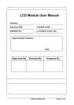
Tuner Monitor Menu
Each tuner has a separate monitor menu and can be viewed independently. While in the monitor menu
the user is not allowed to modify any of the tuner setup parameters, only viewing of the received
parameters are allowed. The menu structure for all tuners are identical thus the following descriptions
is relevant for all three tuners. A description of each of the monitor features is detailed below:
RFBA User Manual
Chrisso Technologies, LLC
Page 12
R X 1 :
MO N I T O R
1 0 5 . 1 MH z
S t
R S S
→R S S
R DS
R DS
R DS
R DS
R DS
R DS
R DS
R DS
R DS
R DS
R DS
R DS
P I L
R DS
S C A
S C A
S C A
P E A
MO D
DE V
DE V
L E F
R GH
L + R
L - R
A MN
MP T
I :
5 5 d B
I : █████████████▎
P I D :
0 x 1 2
P S N A ME :
WA
P T Y :
C OUNT
P T Y N:
B A S E B A
U T C T I ME :
1 9 :
UT C OF F S E T :
- 0 5 :
L OC A L
T I ME :
1 4 :
D A T E ( MD Y )
0 3 / 1 5 /
T P :
T A :
MS :
MU S
D I :
OT L E V E L :
9 . 0
L E V E L :
6 . 0
6 7 K Hz
L E V E L :
3 . 0
9 2 K Hz
L E V E L :
3 . 0
L E V E L :
1 . 2 3 5 V r
K S / MI N U T E :
1
: █████████▎
▏ 1 0
+ : ███████▎
1 0 2
▏
- : █████████▎
▏ 8 2
T : ███████▎
1 0
▏
T : █████████▎
▏ 1 0
: █████████▎
▏ + 2
: ████████ ▏
- 3 5
: █▎
▏
H : ████
2
▏
µ V
C
B
R
L
5
0
5
1
4
C
Y
L
3
0
3
2
1
1
I C
0
%
%
%
%
ms
2 9
3 %
k z
k z
3 %
3 %
d B
d B
4 %
0 %
Figure 10 - Tuner Monitor Menu
RSSI dBµV:
This is the Received Signal Strength Indicator and is displayed in units of dB
relative to 1µV at the antenna input. The RSSI range is valid from 0 dBµV to 65 dBµV.
RSSI:
This is the Received Signal Strength Indicator bar graph and gives a visual
indication of the RSSI amplitude. Maximum scale is 65 dBµV and minimum scale is 0 dBµV
RDS PID:
(e.g. 1F7E).
This is the decoded RDS PID value expressed as a 4 digit Hexadecimal number
RDS PSNAME:
This is the decoded RDS Program Service name (PSNAME) value expressed as an
8 character string.
RFBA User Manual
Chrisso Technologies, LLC
Page 13
RDS PTY:
This is the decoded RDS Program Type (TYP) flag. It is a value from 0-31 and is
displayed as the actual program type, not value based on the region.
RDS PTYN:
This is the decoded RDS Program Type Name (PTYN) value expressed as an 8
digit character. This is used to allow additional descriptions of the program content (e.g.
“Baseball”).
RDS UTC TIME:
This is the decoded RDS Coordinated Universal Time (UTC) value.
RDS CT OFFSET: This is the decoded RDS Clock Time Offset (CT OFFSET) value. This time should
indicate the offset based on the time zone and daylight savings time setting.
RDS LOCAL TIME: This is the decoded RDS Clock Time (CT). This is the calculated value of the
current time based on RDS DATE, UTC and CT OFFSET.
RDS DATE:
This is the decoded RDS Date (DATE). The Date value is expressed in
MM/DD/YYYY format.
RDS TP:
This is the decoded RDS Traffic Program (TP) flag. It is used in conjunction with
the Traffic Announcement (TA) flag for traffic announcements.
RDS TA:
This is the decoded RDS Traffic Announcement (TA) flag. It is used in
conjunction with the Traffic Program (TP) flag for traffic announcements.
RDS MS:
This is the decoded RDS Music/Speech switch. A “0” indicates a Speech
program and a “1” indicates a Music Program.
RDS DI:
This is the decoded RDS Decoder Information (DI) value. The DI value ranges
from 0-15 and identifies various operating modes for the RDS decoders.
Pilot Level:
This is the received FM pilot amplitude and is referenced to 75 kHz deviation.
Maximum scale is 25.5 % and minimum scale is 0 %.
RDS Level:
This is the received FM RDS amplitude and is referenced to 75 kHz deviation.
Maximum scale is 25.5 % and minimum scale is 0 %.
SCA 67 kHz Level: This is the received FM 67 kHz SCA amplitude and is referenced to 75 kHz
deviation. Maximum scale is 25.5 % and minimum scale is 0 %.
SCA 92 kHz Level: This is the received FM 92 kHz SCA amplitude and is referenced to 75 kHz
deviation. Maximum scale is 25.5 % and minimum scale is 0 %.
PPM:
This is a running count of the number of peaks above a specified threshold in
one minute. The default threshold is 105% of 75 kHz. . Maximum scale is 255 and minimum is 0.
This count is reset every time a frequency is tuned.
RFBA User Manual
Chrisso Technologies, LLC
Page 14
Modulation:
This is the FM modulator output and is expressed in percent, referenced to 75
kHz. Maximum scale is 127%. In AM mode the reading is expressed in percentage, relative to 100%
modulation. In WX or PS band the reading is expressed in kHz, referenced to 5 kHz deviation.
Deviation Positive:
This is the positive peaks of the FM modulator output and is an absolute
reading expressed in kHz. Maximum scale is 95.625 kHz and minimum scale is 0 kHz. In AM mode
the reading is expressed in percentage.
Deviation Negative:
This is the negative peaks of the FM modulator output and is an
absolute reading expressed in kHz. Maximum scale is 95.625 kHz and minimum scale is 0 kHz. In
AM mode the reading is expressed in percentage.Audio Left:
This is the output of the stereo
decoder, measuring the Left signal amplitude and is expressed in percent, referenced to 75 kHz.
Maximum scale is 127 %.
Audio Right:
This is the output of the stereo decoder, measuring the Left signal amplitude
and is expressed in percent, referenced to 75 kHz. Maximum scale is 127 %.
Audio Left+ Right: This is the output of the stereo demodulator prior to the demux operation of
the stereo decoder. This is measuring the level of the L+R portion of the composite signal. This
reading is expressed in log units of dB, referenced to 75 kHz.
Audio Left- Right: This is the output of the stereo demodulator prior to the demux operation of
the stereo decoder. This is measuring the level of the L+R portion of the composite signal. This
reading is expressed in log units of dB, referenced to 75 kHz.
AMN:
AM NOISE: This is the measure of amplitude modulation on the FM signal. This
is measured in percent modulation. This measurement is only valid for a strong signal with no
multipath. It is normally meant to measure any AM modulation that might occur in the power amp
stages of the FM transmitter. This is usually best measured with a direct monitor output from the
transmitter.
MPTH:
Multipath: This is the measure of multipath noise on the signal. This is
measured in percent. Values greater than 30% indicate several signal paths at the receiver. The user
should use this indicator to verify proper antenna setup during installation. If this reading is high,
the accuracy of many of the modulation analyzer parameters will be greatly compromised and may
be inaccurate.
MPX Setup Menu
This menu allows user configuration of the MPX output. A description of each of the monitor features is
detailed below:
RFBA User Manual
Chrisso Technologies, LLC
Page 15
MP X :
S E T UP
S OUR C E :
R X 1
→M P
P I
R D
R D
P I
US
P S
US
P T
US
T P
US
T A
US
MS
US
D I
US
C T
R T
A L
S A
X
L
S
S
D
E
N
E
Y
E
E
E
E
E
I
S
L V L
OT L
S T A
L E V
S OU
R P I
A ME
R P S
S OU
R P T
S OUR
R T P
S OUR
R T A
S OUR
R MS
S OUR
R D I
S OUR
S OUR
GN S
S
S E
E
T
E
R
D
S
N
R
Y
C
:
C
:
C
:
C
:
C
C
A
P
7
V
E
L
C
:
O
A
C
:
E
5 K :
E L :
:
:
E :
1 . 2 5 0
0
UR C E : P A S S
ME :
E :
C O
:
P A S S
E :
P A S S
E :
P A S S
E :
P A S S
E
E
S
A
:
P A S S
:
P A S S
S :
R A T I ON:
5
V r ms
9 . 0 %
ON
6 . 0 %
US E R
x 1 2 C 4
- T HR U
N/ A
US E R
UNT R Y
- T HR U
N/ A
- T HR U
N/ A
- T HR U
N/ A
- T HR U
N/ A
- T HR U
- T HR U
S T A R T
4 . 6 d B
Figure 11 - MPX Setup Menu
MPX Level:
The user can adjust the MPX output amplitude. The default setting is 1.25 VRMS
into a 600 ohms load. The user can adjust this level up to a maximum of 1.414 VRMS in 1 mV steps.
Pilot Level:
The user can adjust the 19 kHz pilot on the composite output. The value is
referenced to the MPX Level as a percentage. The user can adjust the pilot level in 0.1 % steps. The
default setting is 9% and has a range between 0 % and 10%.
RDS STATE:
The user can turn the RDS encoder on or off with this adjustment. If the off
state is chosen then the remaining parameters for RDS adjustment will not be adjustable.
RDS Level:
The user can adjust the 57 kHz RDS signal on the composite output. The value is
referenced to the MPX Level as a percentage. The user can adjust the RDS level in 0.1 % steps. The
default setting is 6% and has a range between 0 % and 20%.
PID SOURCE:
The user can set the RDS encoder to use the received PID from Tuner #1 (“PASSTHRU”) or the user specified PID (“USER”). Use the navigation keys to select the PID state. Push the
enter button to have the RFBA accept the new RDS PID state.
USER PID:
The user can set the RDS encoder PID to a specified value. Use the navigation
keys to select the PID value. Push the enter button to have the RFBA accept the new RDS PID. If the
RFBA User Manual
Chrisso Technologies, LLC
Page 16
RDS state is set to “OFF” or the PID SOURCE is not set to “PASS-THRU” then this parameter will not
be adjustable.
PSNAME SOURCE: The user can set the RDS encoder to use the received PSNAME from Tuner #1
(“PASS-THRU”) or the user specified PSNAME (“USER”). Use the navigation keys to select the PID
state. Push the enter button to have the RFBA accept the new RDS PSNAME state.
USER PSNAME:
The user can set the RDS encoder Program Service Name (PSNAME) to a
specified value. Use the navigation keys to select the PS Name. Push the enter button to have the
RFBA accept the new RDS PS Name. If the RDS state is set to “OFF” or the PSNAME SOURCE is not
set to “PASS-THRU” then this parameter will not be adjustable.
PTY SOURCE:
The user can set the RDS encoder to use the received PTY from Tuner #1 (“PASSTHRU”) or the user specified PTY (“USER”).Use the navigation keys to select the PTY state. Push the
enter button to have the RFBA accept the new RDS PTY state.
USER PTY:
The user can set the RDS encoder Program Type (PTY) to a specified value. Use
the navigation keys to select the Program Type. Push the enter button to have the RFBA accept the
new RDS Program Type. If the RDS state is set to “OFF” or the PTY SOURCE is not set to “PASS-THRU”
then this parameter will not be adjustable.
TP SOURCE:
The user can set the RDS encoder to use the received TP from Tuner #1 (“PASSTHRU”) or the user specified TP (“USER”).Use the navigation keys to select the TP state. Push the
enter button to have the RFBA accept the new RDS TP state.
USER TP:
The user can set the RDS encoder Traffic Program (TP) to a specified value. Use
the navigation keys to select the Traffic Program. Push the enter button to have the RFBA accept
the new RDS Traffic Program. If the RDS state is set to “OFF” or the TP SOURCE is not set to “PASSTHRU” then this parameter will not be adjustable.
TA SOURCE:
The user can set the RDS encoder to use the received TA from Tuner #1 (“PASSTHRU”) or the user specified TA (“USER”).Use the navigation keys to select the TA state. Push the
enter button to have the RFBA accept the new RDS TA state.
USER TA:
The user can set the RDS encoder Traffic Announcement (TA) to a specified
value. Use the navigation keys to select the Traffic Announcement. Push the enter button to have
the RFBA accept the new RDS Traffic Announcement. If the RDS state is set to “OFF” or the TA
SOURCE is not set to “PASS-THRU” then this parameter will not be adjustable.
MS SOURCE:
The user can set the RDS encoder to use the received MS from Tuner #1 (“PASSTHRU”) or the user specified MS (“USER”).Use the navigation keys to select the MS state. Push the
enter button to have the RFBA accept the new RDS MS state.
USER MS:
The user can set the RDS encoder Music/Speech (MS) to a specified value. Use
the navigation keys to select the Music/Speech. Push the enter button to have the RFBA accept the
RFBA User Manual
Chrisso Technologies, LLC
Page 17
new RDS Music/Speech. If the RDS state is set to “OFF” or the MS SOURCE is not set to “PASS-THRU”
then this parameter will not be adjustable.
DI SOURCE:
The user can set the RDS encoder to use the received DI from Tuner #1 (“PASSTHRU”) or the user specified DI (“USER”).Use the navigation keys to select the DI state. Push the
enter button to have the RFBA accept the new RDS DI state.
USER DI:
The user can set the RDS encoder Decoder Identification (DI) to a specified
value. Use the navigation keys to select the Decoder Identification. Push the enter button to have
the RFBA accept the new RDS Decoder Identification. If the RDS state is set to “OFF” or the DI
SOURCE is not set to “PASS-THRU” then this parameter will not be adjustable. The valid values for
DI are 0-15 where the least significant bit represents a mono/stereo flag. The RFBA will always use
an internal reference for the stereo pilot and this flag will always be “1”. Thus the RFBA only had
valid values of the odd numbered settings for DI {1, 3, 5…13, 15}.
CT SOURCE:
The user can set the RDS encoder to use the received Clock Time (CT) from
Tuner #1 (“PASS-THRU”) or off (“OFF”).Use the navigation keys to select the CT state. Push the
enter button to have the RFBA accept the new RDS CT state.
RT SOURCE:
The user can set the RDS encoder to use the received Radio Text (RT) from
Tuner #1 (“PASS-THRU”) or off (“OFF”).Use the navigation keys to select the RT state. Push the
enter button to have the RFBA accept the new RDS RT state.
SASS Alignment: The Stand-alone Automatic Stereo Separation alignment menu is used to initiate
the stereo separation routine. To start this routine, connect the MPX output to the RF modulator
(transmitter). Connect the output of the RF Modulator to the Tuner #1 input at a level of 60 dBµV –
117 dBµV (+10dBm). Make sure that tuner #1 is set to the output frequency of the RF modulator
(this is done in the Tuner #1 setup menu). Once the connections are complete and tuner #1 is tuned
to the correct frequency then start the calibration. This will take less than 10 seconds. During the
calibration, the display will show the stereo separation as the algorithm achieves the maximum
value. Upon completion of the SASS the new calibration value will be stored in EEPROM. This
calibration should only need to be completed upon initial setup.
Network Setup Menu
The RFBA has capability to operate via an Ethernet connection. This menu allows the user to set the IP
and Subnet address for the RFBA. A description of each of the monitor features is detailed below:
N E T WO R K
→ I P
S U
GA
MA
:
1
B NE T :
2
T E WA Y : 0
C :
0 3 -
9
5
0
A
2
5
1
C
.
.
.
-
1
2
0
E
6
5
0
3
8
5
1
-
.
.
.
5
0
2
0
8
0
5
0
-
1
5
1
B
.
.
.
5
0
0
0
-
0
0
0
E
1
1
1
F
Figure 12 - Network Setup Menu
IP:
This displays the current IP address of the RFBA. The user can modify this
address by using the buttons to navigate and change. Once the user input is complete, push the
RFBA User Manual
Chrisso Technologies, LLC
Page 18
enter button to have the RFBA accept your request to change IP address. This change will not take
effect until the RFBA is rebooted either through the soft reset command or cycling power.
SUBNET:
This displays the current subnet address of the RFBA. The user can modify this
address by using the buttons to navigate and change. Once the user input is complete, push the
enter button to have the RFBA accept your request to change the subnet address. This change will
not take effect until the RFBA is rebooted either through the soft reset command or cycling power.
GATEWAY:
This displays the current gateway address of the RFBA. The user can modify this
address by using the buttons to navigate and change. Once the user input is complete, push the
enter button to have the RFBA accept your request to change the subnet address. This change will
not take effect until the RFBA is rebooted either through the soft reset command or cycling power.
MAC:
This displays the MAC address of the RFBA. The user cannot modify this value.
It is used for display purposes only.
System Setup Menu:
The RFBA system menu is designed to show the general features of this product. A description of each
of the monitor features is detailed below:
MO
→S E
F I
R E
S O
R E
R E
S C
MO
S Y S T E M
D
R
R
G
F
S
L
R
D
E L
I A L
MWA
I ON
T R
T OR
A Y :
E E N
A N
NO
N
R E
:
E S
E
:
O:
R E V :
E T :
C A
DE F A UL T
T I ME O U T :
K E Y :
I
R F B A - 1 MA
0 0 4 5 1
1 . 0 0
US A
UT I ON! ! !
S :
S T A R T
0 : 3 : 7
1 MI N
NS T A L L E D
Figure 13 - System Menu
Model Number:
This is the Model number of your unit. This value can’t be changed by the user.
Serial Number:
This is the Serial number of your unit. This value can’t be changed by the user.
Firmware Revision:
the user.
This is the Product firmware revision. This value can’t be changed by
Region:
This is the region setting of the RFBA. The RFBA can be set to USA, Europe or
Japan bands. Changing the region setting will change the band frequencies, channel spacing, and
de-emphasis for all tuners. It is not possible to set only some tuners to a particular band. All tuners
will be set to the band selected.
RFBA User Manual
Chrisso Technologies, LLC
Page 19
Soft Reset:
This will perform a soft reset on the product. There is an additional
confirmation menu that you must confirm you really want to reset. Once in the confirmation
screen, select the YES/NO via the left or right keys. Once you’ve made your selection press the
enter key. If you selected “NO” then you will return to the previous screen.
Restore Factory Defaults:
This will reset all user adjustable parameters to the factory
defaults. There is an additional confirmation menu that you must confirm you really want to restore
the factory defaults. Once the selection is confirmed the unit will perform a software reset and all
factory settings will be restored to defaults. The factory calibrations and the SASS calibration will
not be affected by restoring factory defaults.
RELAY:
The relay can be programmed to close on many events. The user can select the
various combinations based on the codes shown in Figure 14. The user may also set these
parameters via the Ethernet connection. The LCD control will show three values separated by a
colon. The first value represents the squelch control for tuner #1, the second value for tuner #2 and
the third value for tuner #3. For example, “1:0:4” would trigger the relay on a “Low RSSI” event on
tuner #1 or a Squelch event on Tuner #3. Please note that if you are using the Tuner #3 audio
outputs in a differential output mode then the relay must be removed or placed in the off state
“0:0:0”.
Tuner #1
Tuner #2
Tuner #3
RELAY
CODE
Squelch
Hi-Jack
Low
RSSI
Squelch
Hi-Jack
Low
RSSI
Squelch
HiJack
Low
RSSI
O
OFF
OFF
OFF
OFF
OFF
OFF
OFF
OFF
OFF
1
OFF
OFF
ON
OFF
OFF
ON
OFF
OFF
ON
2
OFF
ON
OFF
OFF
ON
OFF
OFF
ON
OFF
3
OFF
ON
ON
OFF
ON
ON
OFF
ON
ON
4
ON
OFF
OFF
ON
OFF
OFF
ON
OFF
OFF
5
ON
OFF
ON
ON
OFF
ON
ON
OFF
ON
6
ON
ON
OFF
ON
ON
OFF
ON
ON
OFF
7
ON
ON
ON
ON
ON
ON
ON
ON
ON
Figure 14 - Relay Codes
Screen Timeout: The user may select the timeout setting of the display. If this setting is set to
one minute then after one minute of no user activity then the unit will return to the main menu.
Mod An Key:
The user may enter the 16 byte modulation analyzer key by entering into this
menu. A second menu will be displayed and the user may enter the full 16 byte key. If your product
RFBA User Manual
Chrisso Technologies, LLC
Page 20
is already enabled for a modulation analyzer then the display will show “INSTALLED” and the
secondary menu will not be available.
Front Panel Lock Out
The RFBA has a feature that will lock the front panel from any user input. By default the unit will be in
the unlocked state. To toggle the lock/unlock state, press and hold the up and down button
simultaneously for more than 5 seconds. You will see a screen indicate the current state of the product
for 2 seconds and then return to main screen.
Broadcast Appliance Remote Control
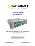
User Interface
The RFBA includes a web server that allows monitor and control access through the Ethernet port. The
various screens can be accessed by the navigation area in the upper left of the web page as shown in
FIGURE 15.
Figure 15 – Web server Navigation Menu
Appliance Home
The Appliance Home page shows the Model Number, Serial Number, Firmware Revision, and whether or
not the Modulation Analyzer is installed.
RFBA User Manual
Chrisso Technologies, LLC
Page 21
Figure 16 - Appliance Home
Receiver Status
The Receiver Status page shows the band and station of each tuner as well as the available RDS
information, RSSI (Received Signal Strength Indicator), and Total Deviation. If the Modulation Analyzer
is not installed, then Tuner 2 and Tuner 3 will show ‘Not Available’ in the Total Deviation cells. It also
shows any Alerts that are active for the RFBA such as ‘Squelched’, ‘Low RSSI’, or ‘Hi-Jacked!’.
Figure 17 - Receiver Status
Modulation Analyzer
The Modulation Analyzer page shows the complete breakdown of the received signals for all three
tuners. A description of each item can be found in the TUNER MONITOR MENU section.
RFBA User Manual
Chrisso Technologies, LLC
Page 22
Figure 18 - Modulation Analyzer
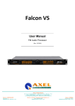
Device Setup
The Device Setup page contains configuration control for the three tuners, the MPX output, Alerts,
Network, and System settings. On each page within the Device Setup, the user must click submit before
any of the changes will be sent to the RFBA.
Receivers
The Receivers page allows the user to set the region for the device (North America, Europe, Japan), the
desired band (AM, FM, Weather (WX), Public Service (PS) ), and the frequency which can be selected
from a pull-down box to ensure valid frequencies for that band and region. In FM Band, the user can
also select whether to enable De-Emphasis in the audio and whether to force the receiver to Mono
(forcing the receiver to Mono on Tuner 1 will also set the MPX output for a Mono signal). There is a pulldown box to set the update rate for the “Modulation Analyzer” and “Receiver Status” pages. The
default update rate is 1.0 second but it can be adjusted to 500msec for fast Ethernet connections or 1
minute for very slow connections. A description of the Bandwidth Filter, Audio Output Level, PPM
Threshold, and Holdoff Time can be found in TUNER SETUP MENU section.
RFBA User Manual
Chrisso Technologies, LLC
Page 23
Figure 19 - Device Setup -> Receivers
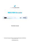
MPX Output
The MPX Output page allows the user to configure the MPX (FM Multiplex) signal including the
percentages for Pilot, RDS, and output amplitude. The default amplitude is 1.25Vrms but is adjustable in
1mV increments. This page also allows for selection of user settings or pass-through of received RDS
data.
RFBA User Manual
Chrisso Technologies, LLC
Page 24
Figure 20 - Device Setup -> MPX Output
Alerts
The Alerts page allows the user to configure alerts for each tuner. The user can also select the option to
trigger a relay, send an email, or both based on the alerts. Details for the Alerts can be found in TUNER
SETUP MENU.
Figure 21 - Device Setup -> Alerts
RFBA User Manual
Chrisso Technologies, LLC
Page 25
Network->IPV4
The IPV4 page allows the user to configure the Ethernet settings including the IP Address of the RFBA,
the Subnet Mask, and the Default Gateway address. It also displays the MAC address for the RFBA. The
“Bandwidth Reduction” pull-down box is used to enable the Ethernet Nagle algorithm which is used to
packetize the Ethernet data. This function can be enabled for long latency, low bandwidth applications
such as remote sites with a satellite connection.
Figure 22 - Device Setup -> Network -> IPV4
Network->SMTP
The SMTP page allows the user to configure the email account settings for use with email alerts.
Figure 23 - Device Setup -> Network -> SMTP
System
The System page displays the same information as the Application Home page, but also includes the
input method for the user to add software keys to add features such as the Modulation Analyzer. Each
key is a 128 bit value represented by 4 groups of 8 hexadecimal characters.
RFBA User Manual
Chrisso Technologies, LLC
Page 26
Figure 24 - Device Setup -> System
Contact Info
The Contact Info page contains contact information for both Chrisso Technologies and Crown Broadcast.
Figure 25 - Contact Info
Product Specifications
Parameter
FM Tuner
Tuning Range
Step Size
Sensitivity
THD
SNR
Stereo Separation
Adjacent Channel Rejection
RF Input impedance
De emphases
AM Tuner
Tuning Range
Step Size
Sensitivity
THD
RFBA User Manual
Note
Region dependant
30 dB SINAD
12 dB SINAD
Min
Typ
76.0
50
Max
Units
107.9
200
MHz
kHz
dBµV
dBµV
%
dB
dB
dB
ohms
µsec
-0.5
-9.5
0.05
75
55
82
50
Noise limited
Region Dependant
Region dependant
20 dB SINAD, 80%AM
80% AM
Off
75
520
9
1710
10
Chrisso Technologies, LLC
1
0.15
kHz
kHz
dBµVemf
%
Page 27
Parameter
SNR
NOAA Weather Tuner
Tuning Range
Step Size
Sensitivity
Adjacent Channel Rejection
Public Service Tuner
Tuning Range
Step Size
Sensitivity
Note
80% AM
Min
Typ
69
162.40
144.000
Balanced Audio Output
Amplitude
THD
Rload = 600 Ω
Relay
Switching Voltage
Carry Current
Static Contact Resistance
Max DC/Peak AC
Max DC/Peak AC
162.55
MHz
kHz
dBµV
dB
175.000
MHz
kHz
dBµV
4
Vp-p
%
1.1
Vrms
%
200
1
Volts
Amps
ohms
14
Vdc
Adc
5
-6.0
12 dB SINAD
Rload = 75 Ω
Units
dB
25
-6.0
60
12 dB SINAD
MPX Output
Amplitude
THD
Max
1
0.1
0.25
0.1
0.200
Power Supply
Voltage
Current
9
12
1
Figure 26 - Specifications
Software Updates
The RFBA has a USB port that can be used for firmware updates to the device. The firmware update
must be loaded onto a flash drive at the root level. The flash filename will always be ‘image.cmg’. Each
time the RFBA boots, it will look to see if there is a flash drive with the ‘image.cmg’ file located on it. If it
is found, it will check the file to make sure it is intact and compare the software revision level. If the
software revision level currently in the RFBA is greater than the ‘image.cmg’ file, then the RFBA will boot
as normal. If the ‘image.cmg’ file is newer, then the RFBA will display that it is updating the firmware. It
is important that the USB drive and the power are not removed during this process. It usually takes 1020 seconds to complete, and the RFBA will reboot once the update is complete. It is possible to update
the software to an older version by holding the enter key when the power is connected to the RFBA.
This will skip the version check and force the update.
RFBA User Manual
Chrisso Technologies, LLC
Page 28
Starting with firmware revision 1.03 there will also be an EEPROM update. This update is similar to the
flash update. The EEPROM filename must always be ‘image.cei’ on the USB drive. After the RFBA has
loaded the latest flash firmware update it will check to verify that it also has the correct EEPROM image.
If the EEPROM image is out of date then it will load the valid image from the USB drive. If the valid
image is not found the product will not boot. Note that it is critical that the firmware and the EEPROM
revision must be compatible for the product to boot. EEPROM updates are rare and will work with
multiple flash firmware updates. For example EEPROM v1.00 will work with flash version 1.00 thru 1.02.
EEPROM v1.03 will work with flash firmware v1.03 and higher (v1.03 is the latest release).
USB flash drive requirements
The RFBA will accept USB drives that conform to the USB specification and are formatted as FAT or
FAT32 (NTFS is not supported). The RFBA does not contain a full operating system such as Windows or
Linux and thus does not contain USB drivers from every USB flash drive manufacturer. As such the RFBA
will only work with devices manufactured that conform to the specifications set forth by the USB Flash
Drive alliance.
Current USB Flash Drive Alliance Members:
Buffalo Technology
Corsair Memory
Crucial Technology
Infineon Technologies
Kingston Technology
Lexar Media
Microsoft
Phison
PNY Technologies
Samsung
SimpleTech
FCC / IC Compliance
Class A Product:
Per US Federal Communications Commission Part 15.105(a):
NOTE: This equipment has been tested and found to comply with the limits for a Class A digital device,
pursuant to part 15 of the FCC Rules. These limits are designed to provide reasonable protection against
harmful interference when the equipment is operated in a commercial environment. This equipment
generates, uses, and can radiate radio frequency energy and, if not installed and used in accordance
with the instruction manual, may cause harmful interference to radio communications. Operation of this
RFBA User Manual
Chrisso Technologies, LLC
Page 29
equipment in a residential area is likely to cause harmful interference in which case the user will be
required to correct the interference at his own expense.
Per Industry Canada ICES-003e:
This Class A digital apparatus complies with Canadian ICES-003.
Cet appareil numérique de la classe A est conforme à la norme NMB-003 du Canada.
Class B Product:
Per US Federal Communications Commission Part 15.105(b):
NOTE: This equipment has been tested and found to comply with the limits for a Class B digital device,
pursuant to part 15 of the FCC Rules. These limits are designed to provide reasonable protection against
harmful interference in a residential installation. This equipment generates, uses and can radiate radio
frequency energy and, if not installed and used in accordance with the instructions, may cause harmful
interference to radio communications. However, there is no guarantee that interference will not occur
in a particular installation. If this equipment does cause harmful interference to radio or television
reception, which can be determined by turning the equipment off and on, the user is encouraged to try
to correct the interference by one or more of the following measures:
Reorient or relocate the receiving antenna.
Increase the separation between the equipment and receiver.
Connect the equipment into an outlet on a circuit different from that to which the receiver is
connected.
Consult the dealer or an experienced radio/TV technician for help.
Per Industry Canada ICES-003e:
This Class B digital apparatus complies with Canadian ICES-003.
Cet appareil numérique de la classe B est conforme à la norme NMB-003 du Canada.
Contact Information
Chrisso Technologies
Website: www.ChrissoTech.com
Email: [email protected]
Crown Broadcast
Website: www.CrownBroadcast.com
Sales
Toll Free: 1-866-262-8972
RFBA User Manual
Chrisso Technologies, LLC
Page 30
Email: [email protected]
Service
24-Hour Toll Free: 1-866-262-8917
Email: [email protected]
RFBA User Manual
Chrisso Technologies, LLC
Page 31