1
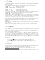
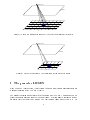
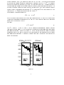
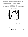
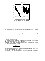
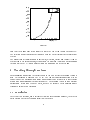
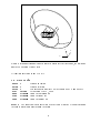
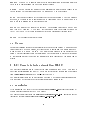
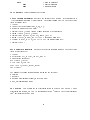
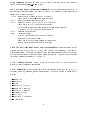
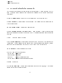
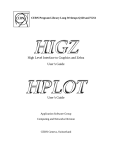
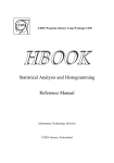
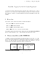
T. Hebbeker, A. Korn, April 30, 1998
Simulation Programs for the L3+Cosmics Experiment
We present a collection of routines useful for simulating cosmic muons in the L3+Cosmics
Experiment. They include code for generating muons, tracking them through the molasse
and through the L3 setup. We dene data formats for the data interchange between these
programs.
1 Overview
In this note we give a short description of the following programs:
CORSIKA | cosmic air shower simulation
L3CGEN |fast muon generator
TRACK |fast tracking through molasse
SIL3C |complete L3+COSMICS detector simulation
The programs and utilities described can be found in directory /pc/hub1c/data/l3cosmic/
on the L3 shift3 machine at CERN. Comments and error reports are welcome 1.
2 Shower simulation with CORSIKA
A program widely used for simulation of extensive air showers is CORSIKA [1]. It provides detailed information on shower content and development depending on the primary
particle. The main drawback is the large amount of required computing time. The time
to process one event strongly depends on primary type and energy.
primary energy primary type time per shower on HP735
excluding elm. cascades
500 TeV
iron
5 min
500 TeV
proton
3 min
5 TeV
proton
4s
1 email: <[email protected]> and <[email protected]>
1
2.1 Steering
A variety of options allow to customize the simulation. These options are set using a data
card with switches.
Type, energy and angular range of the incident primary particle can be given via:
PRMPAR 14
! primary type (proton)
ERANGE 2.00E4 4.00E6 ! energy range in GeV
THETAP 0. 10.
! zenith angle range in degree
PHIP
0. 360.
! azimuth angle range in degree
The energy of the primary is taken at random from a power law distribution inside the
given intervall. The slope of the energy distribution can be dened using:
ESLOPE -2.7 ! slope of energy spectrum
In the original CORSIKA version a lower limit of 80 GeV per nucleon exists. Protons are
the only exception. The user can choose between dierent interaction models. Available
models (VENUS, SYBILL, QGSJET, DPMJET) are descriped in detail in [1].
For the purpose of simulating muons underground the detailed simulation of the electromagnetic component is unnecessary. When these are swiched o via the ag:
ELMFLG T F
computing time is signicantly reduced. For photon induced showers this option has to
be switched on.
For a complete set of available switches we refer to the CORSIKA user's manual [2].
2.2 Installation
This is intended as a short introduction, for detailed information please refer to the user's
manual. It is possible to obtain the CORSIKA code via ftp2 . The version used so far is
5.20. The most recent version is 5.60.
The code is compatible with most systems. It has been succesfully installed on HPUX and LINUX. The suitable options for these two systems are DEC-UNIX and LINUX.
Objectles have to be made by invoking the FORTRAN compiler. For the LINUX version
an additionally generated C{le has to be compiled with the C{compiler. The executable
is created by:
f77 +E1 corsika compilefile.f VENUS.o GHEISHA.o -o corsika.exe
(HP-UX)
(LINUX)
f77 corsika compilefile.f VENUS.o GHEISHA.o TIMER.o -o corsika.exe
2.3 Output
Corsika writes every particle above an energy threshold that passes an observation level
to the output le. The energy thresholds are dened by data card:
ECUTS 10. 10. 10. 10. ! energy cuts in GeV (hadr. muon elec. phot.)
2 Requests for ftp{access should be directed to <[email protected]> or <[email protected]> by e{mail
2
Dierent observation levels can be specied by:
OBSLEV 470E2 ! rst observationlevel in cm
The coordinate system used has the z{axis up, x{axis to magnetic north and the y{axis
to the west. Altitude of L3 surface level is 470m.
2.4 Utility programs
We provide a program corread to convert a CORSIKA output le into the /L3CEVT/
format used by L3+Cosmic programs. As this format contains only muons at ground
level the lesize is reduced. This program also has a built in tiling mechanism, for better
usage of MC statistics. This mechanism subdivides the shower area into squares of 50m
length. The particle trajectories are extrapolated to a plane down in the depth of the L3
cavern parallel to the surface. The coordinates of particles in each square are then moved
by the distance of the corrosponding square to the middle. That means that every 50m
times 50m area is treated as an independent detector. This is aquivalent to smearing the
shower axis with a xed detector position [3].
The program cors2gobi is supplied to visualize the shower development. This program
uses XGobi [4][5] as viewer and CORSIKA's plot version.
3
Shower axis
Surface
0
0
Figure 1: Only a few muons of a shower hit the detector situated at the origin.
Shower axis
Surface
0
0
Figure 2: One of the subevents. The coordinate system has been moved.
3 The generator L3CGEN
Since CORSIKA is rather slow, it is necessary to build a simple muon generator based on
a parameterization of the CORSIKA results.
The parameterization was obtained in the following way: CORSIKA 5.20 was used with
default options to generate showers (Gheisha/Venus). Electromagnetic cascades were not
simulated since they don't give muons. The zenith angle range was set to = 0 70
4
degrees (j cos j > 0:34), the maximum permitted by CORSIKA. The energy distribution
of the primary baryon hitting the atmosphere is assumed to fall 1=Ep2:7. As primary
particles we considered protons (p), helium (He) and iron nuclei (Fe). Protons constitute
the dominant component in the energy range of interest, iron represents heavy nuclei. To
simulate the muon energy spectrum above a threshold of E we must consider primary
energies above a corresponding threshold Ep. It is chosen as the smallest number which
fulls: for Ep < Ep muon energies are always below E .
For protons we nd approximately:
Ep (1:5 3) E
(1)
where the bigger factor applies to small muon energies near 2 GeV and the smaller factor
is valid for muon energy thresholds of a few 100 GeV. For p induced showers we generated
muons down to energies of 2 GeV.
For iron:
Ep 25 E
(2)
for E > 200 GeV. Since CORSIKA (in the standard conguration) cannot simulate
iron showers below 5000 GeV, we were not able to obtain the corresponding muon energy
and angular spectrum below E = 200 GeV. In the accessible energy range the muons
originating from p, He and Fe look very similar, as gure 3 demonstrates for the energy
and angular distributions. Therefore we nally used only p showers to determine the
muon distributions.
dN/dlog10(E) * E**2
Eµ =
200-600 GeV
dN/dcosΘ
Eµ =
200-600 GeV
p
Fe
p
Fe
log10(E)
cosΘ
Figure 3:
5
The muons existing at an altitude of 470 m were written to a le and analysed later on.
An absolute prediction of the primary or secondary ux is not provided by CORSIKA.
First we investigated the energy distribution integrated over the zenith angle range j cos j >
0:4. The value of 0:4 > 0:34 was chosen to avoid `edge eects'. Since the muon energy
distribution falls o approximately as E3 , we studied the distribution
dN = dN = E 3 dN
E2 d log
(3)
E d(1=E2 )
dE
which is at for dN=dE 1=E3 . The result shows gure 4. The shape can be paramedN/dlog10(E) * E**2
log10(E)
Figure 4:
terized by the polynomial
1:922 10:17 L + 18:75 L2 8:387 L3 + 1:107 L4
(4)
as demonstrated in the same gure. Here L log10 (E =GeV). Note that we plotted all
muons produced in all showers, ignoring correlations within single showers.
Next we analyzed angular distributions as a function of muon energy. While the azimuthal
angle has a at distribution, the distribution of cos is well represented by a linear function
in c cos , see gure 5 (for muons near 17 GeV and for muon energies around 700 GeV):
dN 1 + a (1 jcj)
(5)
dc
The coecient a is muon energy dependent (g. 6). A good parameterization is
6
dN/dcosΘ
17 GeV
700 GeV
cosΘ
cosΘ
Figure 5:
a(l ln(E =GeV)) = 1:903 + 0:1434 l + 0:0145 l2
(6)
The distribution of the muon charge was not investigated in detail. There is no strong
correlation to energy or angle. On average:
N + = 1:3
(7)
N
The FORTRAN program L3CGEN is based on these parameterizations. It allows to
generate muons at the surface of the L3 site with a speed of up to 1 million events per
minute on a HP735 workstation.
The muons are produced `inclusively', which means that the program generates muons
`one by one' and does not deliver multi-muon events.
By counting the number of muons produced around 100 GeV, the generator can normalize
with respect to the known ux of about
dN
3 2
(8)
d cos d dE d A 3 10 =m =s=GeV=sr
and thus provide a relation between the number of generated events (for a given surface
area) and the corresponding time interval.
Optionally the impact points at surface levels and the zenith angles can be constrained
7
a
ln(E)
Figure 6:
such that the muons have a fair chance to reach the L3C setup (phase I or phase II).
The selection is done conservatively: muons within the L3C acceptance are denitely not
rejected.
The output format contains muon impact point, direction, energy and charge; it can be
selected from a list of four options, see appendix. Among them is a ntuple (corresponding
to common /L3CEVT/) and a packed binary le using only 8 Bytes per muon.
4 Tracking through molasse
For propagating muons from the surface down to the L3-Detector the program track3 is
used. This program is based on GEANT [6]. The complete underground setup with all
shafts is modelled. Surrounding molasse is approximated as a cone with a lower radius
of 60 m and an opening angle of 60o (see gure 4). The program is able to read dierent
dataformats. It can read CORSIKA data, all L3CGEN formats. These dataformats are
recognized using the le extension.
4.1 Installation
There exist two versions, one is interactive (mainly for debugging purpose), the other a
batch version. For each version an install le is provided.
8
z
x
y
Figure 7: setup underground: Inside a cone of molasse three access shafts, the main hall
and the LEP3 volume can be seen
All routines are stored in one CAR le.
4.2 Data cards
SMEAR
SELECT
REUSE
EVOL
HBNM
FINM
FONM
T
T
T
volume
filename
filename
filename
!
!
!
!
!
!
!
enable smearing
enable selection
smear showers until they hit l3 requires SMEAR and SELECT
stop volume TSCN, LEP3
name of histogram le
name of input le
name of output le
SMEAR The shower axis is smeared in a circle of 140 m diameter. Without smearing
the shower axis always goes through the origin.
9
SELECT If SELECT is enabled particles with an extrapolated hit position outside a
circle of 16 m radius around the L3 vertex are not tracked.
REUSE REUSE smears the primary vertex again until a particle has a chance to hit
the L3 volume. This option requires SMEAR and SELECT to be activated.
EVOL Particles are stopped at the borders of the specied volume. The two volumes
are LEP3, a cylinder of 9.5 m radius and 14.2 m length and TSCN a box of 12.35 m x
6.35 m x 0.33 m around the t0 detector position.
FINM The name of the input le is specied. The program can read CORSIKA les
and /L3CEVT/ formats. A CORSIKA le is assumed when the lename starts with
'DAT'. The /L3CEVT/ les are recognized via the le extensions '.l3c' and '.ntp'.
FONM This denes the output le path.
4.3 Output
The output contains the particle coordinates in the selected stop volume. Two possibilities
can be enabled: The LEP3 volume, a cylinder of 9.5 m radius and 14.2 length and TSCN
a box of 12.35 m x 6.35 m x 0.33 m. The particles are stopped at the borders of the
volume. Output coordinates are L3 coordinates. The format used is described in chapter
6. If histogram output is selected the amount of matter traversed by the muon can be
plotted.
5 L3+Cosmic detector simulation SIL3C
The detector simulation SIL3C is part of the cosmics analysis code COL3. This code is
split into several PATCHY car les [7]. The most recent ocial version can be obtained
from /user/cosmic/col3 on the L3 HP{cluster at CERN.
The simulation includes the t0 detector and L3 setup. The complete underground geometry is present. Details on the detector simulation can be found in [8].
5.1 Installation
After unpacking the .tar le the execution of col3/Install Col3 creates necessary directory structures and builds the COL3 library.
The batch version is installed via col3/v211/bin/install l3c simu. Install le for the
interactive version is col3/v211/bin/install l3c simu int.
10
Figure 8: Simulated event of a 200 GeV muon passing the L3+Cosmics detector (Phase
II). The structure inside the support tube is not drawn. At the bottom of the picture an
electromagnetic shower generated in the iron yoke can be seen.
5.2 Data cards
The simulation is steered by a set of data cards. An example run le can be found
at col3/v211/bin/l3c simu.run. The complete list of available datacards is part of
utl3c.car and sil3c.car. Only a subset can be described here.
GEOM volumekey parameter
! volumes
SETS detectorkey parameter ! detectors
FLMP filename
! path to eldmap
IOPA
! input/output
COSM
! cosmic input
DAQC
! output in new dataformat [9]
DAQT datetime
! time for database
CUTX cutoff
! cutos for special tracking media
PHAS phase
! phase of L3C setup
11
DBL3
DBL3
DBMU
! path to database
! general database
! muon database
TRIG nevents Triggers a number of events.
GEOM volume parameter Species the volumes to be created. If the parameter is
-1 the corresponding volume is not created. The default parameter is 3. There are three
levels of volume keys :
1. 'LEP3'
2. 'xREG' for the 6 regions (x=T,E,H,F,M,A)
3. geometry keywords per REGion:
T region : 'TECH', 'TRBP' (xxBP stands for Beam Pipe structures)
E region : 'EBAR', 'ECAP', 'ERBP'
H region : 'HBAR', 'HCAP', 'HMFL', 'SBAR', SCAP'
F region : 'FCAP', 'FRBP', 'FQUA' (FQUA for quads. geometry)
M region : 'MBAR', 'MCAP', 'MGNT' (MGNT for magnet geometry)
A region : 'TSCN'
SETS detector parameter Species the detector response required. There are three
levels of detector keys :
1. 'LEP3'
2. detector 'SCNT', 'MUCH', 'JTRG', 'TSCN'
3. subdetector keywords :
SCNT 'SBAR', 'SCAP'
MUCH 'MBAP', 'MBAZ'
JTRG 'JTMU', 'JTSC', 'JTL2', 'JTL3'
TSCN 'T0SC'
The parameter denes the appropriate action for the detector:
0 Nothing
1 Hits only
2 Hits and digitizations (default, may be omitted)
3 Hits, digitizations and noise
PHAS setup This denes the t0 scintillator setup to be used. For PHASE 1 48m2
scintillator are created, PHASE 1.5 corresponds to 72m2 covered. Three scintillators of
72m2 are installed for PHASE 2.
12
FLMP lename Species the path to the magnetic eld map for the yoke and coil
region. Usually col3/db/l3 50.map is used.
IOPA key unit [chopt recordlength lename] Denes input and output les. If
unit is negative optional parameters have to be given. The parameter chopt denes open
parameters: Avalaible keys are:
COSM input of cosmic events in /L3CEVT/ format
chopt has to be 'LI' (C{library open for input)
GETY input of standard generator events
DAQC output of the new L3+COSMICS DAQ format [9]
chopt has to be 'AO' (ASCII open for output)
the new format requires wiring information from muon database
A correct DAQ time has to be specied as well
SAVX standard SIL3C output
HSTO histogram output
here the list of parameters is slightly dierent:
unit chopt recl maxrec lename
chopt has to be 'RO' (open random access output)
maxrec gives the maximum lesize in records
DBL3 key unit [recl maxr chopt dopt] vers lename Denes database to use.
Allowed keys are 'DBL3', 'DBMU', 'DBSC' and 'DBJT'. The database is specied by
version and lename. If the unit is negative some additonal parameters have to be given.
The rst parameters are recordlength and maximum le size. The next two are options
for le and database opening (e.g. 'R' and ' ').
DAQT yymmdd hhmmss Sets DAQ time of the event. The DAQ time is needed to
access the correct database information.
CUTX parameter Kinetic energy cuts in special tracking media on (X=E,G,H,M,N)
electrons, gammas, hadrons, muons and neutrons. For each medium a parameter is
needed:
1 | gas in TEC
2 | special air
3 | Brass
4 | gas in HCAL/FWCH
5 | gas in Mu-P chamber
6 | gas in Mu-Z chamber
7 | Uranium mixture
8 | RPC Gas
9 | Gas in FB Mu-chamber
10 | Aluminium
13
11 | Iron
12 | Molasse above L3
5.3 Interactive simulation commands
The interactive simulation is mainly useful for test purposes. As user interface KUIP is
used. An online help mechanism can be invoked with HELP. Here is a short list of useful
commands:
DTREE volume level Draws the tree of volumes up to the specied level.
DSPEC volume Displays volume specications. Used parameters are printed and all
3 projections drawn.
SCALE xscale yscale Changes the drawing scale.
DRAW volume [theta phi psi u0 v0 su sv] Draws a volume. Drawn is a projection
under viewing angles theta and phi rotated by psi. Additional oset and scale factors can
be given.
NEXT Clears the graphic window.
KINE ikine parameter Denes kinematics of an event. For ikine = 1 a single particle
is generated. Needed parameters are particle type, incident angle theta and phi, energy
and three vertex coordinates. Only active if GETY and COSM are not used.
TRIG nevents Triggers a number of events.
DXYZ Draw particle trajectories.
Dotted blue
Dashed green
Solid red
Dotted black
|gammas
|muons
|other charged particles
|neutral hadrons and neutrinos
DHITS Draws hits.
DAXIS xo yo zo size Draw mother coordinate system axis at (xo,yo,zo). The fourth
parameter species the length drawn.
14
PHITS Prints hit specications.
PDIGI Prints digitisations.
6 Data format and Interface library
The underlying data structure used for data interchange is based on the /L3CEVT/ common block. This structure is inspired by the HEP common [10]. The common /L3CEVT/
contains the output variables for one event:
nevl3c
nshl3c
nrul3c
ndal3c
timl3c
event number (1,2,3,....)
shower number producing this event(e.g. CORSIKA event nr.)
run number (e.g. CORSIKA run nr.)
Modied Julian date (Universal Time) (50814 - ...)
day time, fraction of a day (Universal Time) (0 ... 0.99999..)
time = time of impact of primary particle on atmosphere
idpl3c
identier of primary particle impinging on atmosphere
following jetset standard, e.g. proton = 2212
ppl3c(4) 4 momentum of primary particle:
ppl3c(1) = x momentum component = px/ptot (-1 ... 1)
ppl3c(2) = y momentum component = py/ptot (-1 ... 1)
ppl3c(3) = z momentum component = pz/ptot (-1 ... 1)
ppl3c(4) = energy in GeV
(L3 coordinate system)
vpl3c(4) impact point/time of primary particle (in upper atmosphere):
vpl3c(1) = x coordinate in m
vpl3c(2) = y coordinate in m
vpl3c(3) = z coordinate in m
vpl3c(4) = time dierence of impact with respect to timl3c in s
(normally 0 !)
(L3 coordinate system)
nl3c
number of secondaries arriving at surface of earth (here: 1)
ipl3c(..) identier of secondary particle
following jetset standard muon = 13, antimuon = -13
pl3c(4,..) 4 momentum of secondary particle:
pl3c(1) = x momentum component = px/ptot (-1 ... 1)
pl3c(2) = y momentum component = py/ptot (-1 ... 1)
pl3c(3) = z momentum component = pz/ptot (-1 ... 1)
pl3c(4) = energy in GeV (2 ...)
(L3 coordinate system)
vpl3c(4,..) impact point/time of secondary (surface):
vl3c(1) = x coordinate in m
vl3c(2) = y coordinate in m
15
vl3c(3) = z coordinate in m
vl3c(4) = time dierence of impact with respect to timl3 in s
(L3 coordinate system)
Optional it is possible to use the same common block for header information, agged by
a negative event number nevl3c. Typically there is one such block per le (e.g. at the
beginning)
nevl3c -1
ndal3c date of generation (s. above)
timl3c version (and revision number) of program producing le
(e.g. generator, e.g. version 2.7)
idpl3c program code: 101 = corread
202 = l3cgen2
301 = track
ppl3c, program dependent parameters
vpl3c here: ppl3c(1) = ntot, ppl3c(2) = emin, ppl3c(3)=igeom
For input/output we provide the library l3cout. This library provides a collection of
routines to read and write the /L3CEVT/ structure to disk. A C{style le format based
on the CFIO package of CERNLIB (Z310) is used.
Files are opened with a call to OPENC. The returned value for the le descriptor LUN has to
be used in all other calls. As status variable IERR is returned. After succesfull execution
it is set to zero. Normally les are written via WRITEL3CEVT and read by READL3CEVT. To
read the compressed MINI format optionally written by L3CGEN the routine READL3M
has to be called. As an option the information is read from integer variables INT1 and
INT2 and not from a le, if LUN is zero.
Routines in l3cout
c
c
c
c
c
c
c
c
c
c
OPENC(LUN,FNAME,IERR)
WRITEL3CEVT(LUN,IERR)
READL3CEVT(LUN,IERR)
READL3M(LUN,INT1,INT2,IERR)
PUTWORD(LUN,WORD,IERR)
WRITEREAL(LUN,RWORD,IERR)
WRITEINT(LUN,IWORD,IERR)
GETWORD(LUN,WORD,IERR)
READREAL(LUN,RWORD,IERR)
READINT(LUN,IWORD,IERR)
7 Acknowledgements
The members of the Nijmegen COL3 programming team A. van Mil, B.Petersen, H.
Wilkens contributed greatly to TRACK and SIL3C. For providing CORSIKA we would
like to thank D. Heck and J. Knapp.
16
8 References
[1] D. Heck, J. Knapp, J.N. Capdevielle, G. Schatz, and T. Thouw. CORSIKA: A Monte
Carlo Code to simulate Extensive Air Showers. Forschungszentrum Karlsruhe, 1998.
Report FZKA 6019.
[2] J. Knapp and D. Heck. Extensive Air Shower simulation with CORSIKA: A User's
Guide. Forschungszentrum Karlsruhe. Internal Report (1998) unpublished (updated
version of Report KfK 5196 B.
[3] G.Battistoni, C. Bloise, A.Ferrari, M.Monteno, V.Patera, and E. Scapparone. Astroparticle Physics, (7):101{108, 1997.
[4] Deborah F. Swayne, Dianne Cook, and Andreas Buja. Users Manual for XGobi,
a Dynamic Graphics Program for Data Analysis Implemented in the X Windows
System. Bellcore Technical Memorandum, 1991.
[5] Xgobi homepage: http://lib.stat.cmu.edu/general/XGobi.
[6] R. Brun et al. Geant 3. CERN DD/EE/84-1, september, 1987. revised.
[7] H.Klein and J.Zoll. PATCHY reference manual (5.04). CERN, 1995.
[8] A. Korn. Cosmic muons in the L3 detector, Diploma thesis, 1998. in preparation.
[9] B.Petersen and T.Wijnen.
L3 COSMICS Dataformat, 1997.
http://www.hef.kun.nl/l3c/Pub/data format0 B.ps.
[10] Editors: G. Altarelli, R. Kleiss, and C. Verzegnassi. Z Physics at LEP1, 1989. CERN
Yellow Report 89{08.
17