1
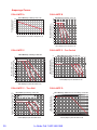
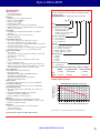
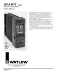
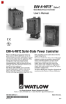
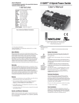
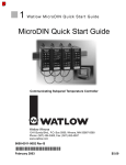
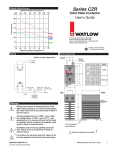
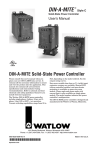
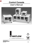
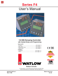
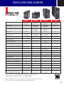
®
THE DIN-A-MITE
FAMILY
WATLOW DIN-A-MITE
®
DIN-A-MITE
Style A
DIN-A-MITE
Style B
DIN-A-MITE
Style C
DIN-A-MITE
Style D
Up to 25A
@ 600VAC
Up to 40A
@ 600VAC
Up to 80A
@ 600VAC
Up to 100A
@ 600VAC
①
No
Up to 33A
@ 600VAC
Up to 80A
@ 600VAC
Gang 2 units
3-Phase, 3 leg①
No
Up to 22A
@ 600VAC
Up to 70A
@ 600VAC
Gang 3 units
200KA SCCR
Yes
Yes
Yes
Yes
24, 120 & 240VAC
4.5-32VDC
24, 120 & 240VAC
4.5-32VDC
24, 120 & 240VAC
4.5-32VDC
24, 120 & 240VAC
4.5-32VDC
Multizone VAC and VDC Input
No
Yes
Yes
No
4-20mA DC Input - Variable
Time Base Output
Yes
Yes
Yes
Yes
Phase Angle Fire Output➁
No
No
Yes
No
Manual Control Via Potentiometer Input, or
0-5, 1-5 or 0-10VDC Linear Voltage Input
No
No
Yes
No
Shorted SCR Alarm
No
Yes
Yes
Yes
Open Heater Alarm
No
No
Yes
No
1-Phase①
3-Phase, 2 leg
VAC and VDC - Burst Fire
Contactor Input
1-phase only
With “S” input only
Load Current Monitor CT
No
No
No
Yes
On Board Semiconductor Fusing
No
No
No
Yes
DIN-Rail Mount
Yes
Yes
Yes
No
Sub-Panel Mount
Yes
Yes
Yes
Yes
Cabinet Thru-Wall Heat Sink Mount
UL® 50 and Class 1, Div. 2 per ANSI/ISA 12.12.01
No
No
Yes
No
Electrically Touch-Safe Package
Yes
Yes
Yes
Yes
Back-to-Back SCR Design
Yes
Yes
Yes
Yes
®
UL 508 Listed/C-UL /CE w/filter
®
Dimensions
Controller Weight: lbs (kg)
Controller Weight w/fan: lbs (kg)
Yes
Yes
3.7 H x 1.8 W x 3.9 in. D
(95 x 45 x 98 mm)
3.7 H x 3.1 W x 4.9 in. D
(95 x 80 x 124 mm)
0.71 (0.32)
N/A
1.5 (0.68)
N/A
➁
Yes
Yes
6.0 H x 3.1 W➂ x 5.7 in. D 7.25 H x 2.5 W x 9.4 in. D
(150 x 80 x 146 mm)
(185 x 65 x 240 mm)
2.6 (1.18)
3.2 (1.45)
6.5 (2.95)
N/A
①
Refer to curves on reverse side for specific ratings.
Phase angle fire is not CE approved for conducted or radiated emissions.
➂
Will fit within the width dimension of most comparable MDRs.
➁
Watlow® and DIN-A-MITE® are registered trademarks of Watlow Electric Manufacturing Company.
UL® and C-UL® are registered trademarks of the Underwriter’s Laboratories, Inc.
WIN-DFM-0310
38
Amperage Curves
DIN-A-MITE B
DIN-A-MITE A
90
85
20
80
15
10
65
60
55
se
ha
eg
45
,2l
50
ase
Max. Internal Enclosure Ambient Temperature (°C)
70
P
gle
Sin
25 30 35 40 45 50 55 60 65 70 75 80 85
75
g
e, 3 le
0
Natural Convection
s
3-pha
5
Max. Internal Enclosure
Ambient Temperature (°C)
25
3-ph
Current (Amperes) into
a Resistive Load
DIN-A-MITE Style B Ratings at 100% On
DIN-A-MITE Style A Ratings at 100% On
30
40
35
30
25
0
5 10 15 20 25 30 35 40 45 50 55 60
Current (Amperes) into a Resistive Load
DIN-A-MITE C
DIN-A-MITE C - Fan Cooled
DIN-A-MITE Style C Ratings at 100% On
DIN-A-MITE Style C Ratings at 100% On
80
90
75
85
as
e
g
e
g
le
le
3
40
Ph
2
e,
e,
as
45
gle
50
ph
as
g
2 le
leg
40
Ph
se,
e, 3
45
55
as
le
ng
50
ha
has
3-p
55
Fan-Cooled
60
ph
Si
60
65
3-
65
70
Sin
70
3-p
Max. Internal Enclosure
Ambient Temperature (°C)
75
3-
Max. Internal Enclosure
Ambient Temperature (°C)
Natural Convection
80
35
30
25
35
0
30
5 10 15 20 25 30 35 40 45 50 55 60 65 70 75 80 85 90
Current (Amperes) into a Resistive Load
25
0
5 10 15 20 25 30 35 40 45 50 55 60 65 70 75 80
Current (Amperes) into a Resistive Load
DIN-A-MITE D
Recommended Max.
Enclosure Temperature is 176°F (80°C)
75
70
65
Thru-Wall Heat Sink
2
e,
45
leg
35
leg
e, 3
has
40
e
as
50
as
Ph
Ph
3-
55
gle
Sin
60
30
Max. Internal Enclosure
Ambient Temperature (˚C )
85
80
75
70
65
60
55
50
45
40
35
30
25
25
0
5 10 15 20 25 30 35 40 45 50 55 60 65 70 75 80
Current (Amperes) into a Resistive Load
39
DIN-A-MITE Style D Natural Convection Ratings at 100% On
DIN-A-MITE Style C Ratings at 100% On
80
3-P
Ambient Air Around Heatsink Fins (°C)
DIN-A-MITE C - Thru-Wall
0
5 10 15 20 25 30 35 40 45 50 55 60 65 70 75 80 85 90 95 100 105
Current (Amperes) Into a Resistive Load
to Order Call 1.800.345.0369
Style A DIN-A-MITE
Operator Interface
• Command signal input
• Input indicator light LED
Amperage
• Single phase, see the output rating curve
• Max. I2t for fusing: 4000A2sec
• Latching current: 200mA
• Holding current: 100mA
• Power dissipation is 1.2 watts per amp switched
• 200KA SCCR, Type 1 and 2 approved with the recommended
fusing; see user manual.
Line Voltage
• 20 to 660V~(ac) model number dependent; see ordering
information
• Off-state leakage: 1mA at 77°F (25°C) max.
• 50/60Hz independent
Control Mode-Zero Cross
• Input control signal Type C: VÎ(dc) input contactor
• Input control signal Type K: V~(ac) input contactor
• To increase service life on contactor input models, the cycle time
should be less than three seconds
• Input Control Signal Type F: 4 to 20mAÎ(dc) proportional variable
time base control; 3 cycles on, 3 cycles off at 50% power
Input Command Signal
• AC contactor
24VÅ(ac) ±10%, 120VÅ(ac) +10/-25%, 240VÅ(ac) +10/-25% @
25mA max. per controlled leg
• DC Contactor
4.5VÎ to 32VÎ(dc): max. current @ 4.5 VÎ(dc) is 8mA
per leg
• Loop powered linear current
4mAÎ to 20mAÎ(dc): loop-powered, input Type F0 option only
(requires current source with 6.2VÎ(dc) available, no more than
three DIN-A-MITE inputs can be connected in series)
Agency Approvals
• UL® 508-listed and C-UL® File E73741
• CE with proper filter:
89/336/EEC Electromagnetic Compatibility Directive
73/23/EEC Low Voltage Directive
EN 61326 Industrial Immunity Cass A Emissions
EN 50178 Safety Requirements
Input Terminals
• Compression: will accept 0.2 to 2 mm2 (24 to 14 AWG) wire
Line and Load Terminals
• Compression: will accept 0.8 to 8.4 mm2 (18 to 8 AWG) wire
Operating Environment
• Up to 176°F (80°C); see the output rating curve chart for your
application
• 0 to 90% RH (relative humidity), non-condensing
• Installation only tested to 3,000 meters
• Units are suitable for “Pollution degree 2”
Mounting
Options include DIN-rail or standard back panel mounting
• The DIN-rail specification is: DIN EN 50022, 35 mm by 7.5 mm
• Mount the cooling fins vertically
Dimensions
• Height: 3.7 in. (95 mm) high x 1.8 in. (45 mm) wide x
3.9 in. (98 mm) deep
• Weight: 0.71 lb (0.32kg)
Ordering Information
To order, complete the code number on the right with the
information below.
DIN-A-MITE Style A = Solid State Power Controller
1 __
_D_ __
0 ___ __ __
0 - __ __ __ __ - __
A __
Phase
1 = 1-phase, 1 controlled leg
Cooling and Current Rating
0 = Natural convection current
rating 18A @ 50˚C (see
derating curve for current rating
at other temperatures)
Line and Load Voltage
02 = 24 to 48VÅ(ac)
24 = 100 to 240VÅ(ac)
60 = 277 to 600VÅ(ac)
Input
C0 =
F0 =
K1 =
K2 =
K3 =
Type
4.5 to 32VÎ(dc) contactor
4 to 20mAÎ(dc) proportional
22 to 26VÅ(ac) contactor
100 to 120VÅ(ac) contactor
200 to 240VÅ(ac) contactor
Manual Language
0 = English
1 = German
2 = Spanish
3 = French
Custom Parts Designation
00 = Standard parts
Recommended Semiconductor Fuse and Fuse Holder
Fuse
Watlow
17-8025
Holder
17-5110
Cooper Bussmann®
FWC25A10F
B24202
Ferraz Shawmut
L330014
G81219
Output Rating Curve
30
Current (Amps) into
a Resistive Load
Specifications
DIN-A-MITE Style A Ratings at 100% On
25
20
15
10
5
0
25 30 35 40 45 50 55 60 65 70 75 80 85
Max. Internal Enclosure Ambient Temperature (°C)
Cooper Bussman® is a registered trademark of Cooper Bussman, Inc.
Specifications are subject to change without notice.
www.starelectricinc.com
40
Style B DIN-A-MITE
Specifications
Ordering Information
Operator Interface
• Command signal input and indication light
• Alarm output and indication light
Amperage Rating
• See the output rating curve
• Max. surge current for 16.6ms, 380A peak
• Max. I2t for fusing is 4,000A2s
• Latching current: 200mA min.
• Holding current: 100mA min.
• Off-state leakage 1mA at 77°F (25°C) max.
• Power dissipation = 1.2 watts per amp per leg switched
• 200KA SCCR, Type 1 and 2 approved with the recommended
fusing; see user manual.
Line Voltage
• 20 to 660V~(ac) model number dependent; see ordering
information
Control Mode, Zero-Cross
• Input control signal Type C: VÎ(dc) input contactor
• Input control signal Type K: V~(ac) input contactor
• To increase service life on contactor input models the cycle time
should be less than three seconds
• Input Control Signal Type F: 4 to 20mAÎ(dc) proportional variable
time base control
Input Command Signal
• AC contactor
24VÅ(ac) ±10%, 120VÅ(ac) +10/-25%, 240VÅ(ac)
+10/-25% @ 25mA max. per controlled leg
• DC Contactor
4.5 to 32VÎ(dc): max. current @ 4.5VÎ(dc) is 6mA
per leg. Add 2mA per LED used to the total current
• Loop powered linear current
4 to 20mAÎ(dc): loop-powered, input Type F0 option only
(requires current source with 6.2VÎ(dc) available, no more than
three DIN-A-MITE inputs connected in series); 3 cycles on, 3
cycles off at 50% power
Alarm
Shorted SCR Alarm Option
• Alarm state when the input command signal off and a 10A or
more load current is detected by the current transformer (two
turns required for 5A and three turns for 2.5A)
Alarm Output
• Energizes on alarm, non-latching
• Triac 24 to 240V~(ac), external supply with a current rating of
300mA @ 77°F (25°C), 200mA @ 122°F (50°C), 100mA @
176°F (80°C) and a holding current of 200 µA with a latching
current of 5mA typical
Agency Approvals
• CE with proper filter:
89/336/EEC Electromagnetic Compatibility Directive
EN 61326: Industrial Immunity Class A emissions
73/23/EEC Low Voltage Directive
EN 50178 Safety Requirements
Installation category III, pollution degree 2
•
UL® 508 listed and C-UL® File E73741
Fuse Rating
20A
25A
40A
50A
Watlow
17-5110
17-5110
17-5114
17-5114
Fuse Holder Part Number
Cooper Bussmann®
CHM1G
CHM1G
CH141G
CH141G
Output Rating Curve
DIN-A-MITE Style B Ratings at 100% On
85
Ferraz Shawmut
G81219
G81219
J081221
J081221
Current Rating Table
Phase
Cooling
Current
at 122˚F
(50°C)
1
2, 8
3, 9
0
0
0
35A
25A
17A
Natural Convection
80
75
70
65
g
leg
45
, 2 le
50
ase
Ph
55
gle
Sin
60
ase
Max. Internal Enclosure Ambient Temperature (°C)
90
se, 3
Specifications are subject to change without notice.
Recommended Semiconductor Fuse and Fuse Holders
Fuse Part Number
Fuse Rating
Watlow
Cooper Bussmann® Ferraz Shawmut
20A
17-8020
FWC20A10F
K330013
25A
17-8025
FWC25A10F
L330014
40A
17-8040
FWC40A14F
A093909
50A
17-8050
FWC50A14F
B093910
3-pha
41
B __ __ - __ __ __ __ - __ __ __ __
D __
__
Phase
1 = 1-phase, 1 controlled leg
2 = 3-phase, 2 controlled legs
3 = 3-phase, 3 controlled legs
8 = 2 independent zones
(input control C or K)
9 = 3 independent zones
(input control C or K)
Cooling and Current Rating Per Pole
0 = Natural convection standard
DIN-rail or panel mount heat sink
Line and Load Voltage
02 = 24 to 48VÅ(ac)
24 = 120 to 240VÅ(ac)
60 = 277 to 600VÅ(ac)
Input Control Signal
C0 = 4.5 to 32VÎ(dc) contactor
F0 = 4 to 20mAÎ(dc) proportional
K1 = 22 to 26VÅ(ac) contactor
K2 = 100 to 120VÅ(ac) contactor
K3 = 200 to 240VÅ(ac) contactor
Alarm
0 = No alarm
S = Shorted SCR alarm
User Manual
0 = English
1 = German
2 = Spanish
3 = French
Custom Part Numbers
00 = Standard part
XX = Any letter or number, custom options, labeling, etc.
3-ph
Input Terminals
• Compression: will accept 0.2. to 2 mm2 (24 to 14 AWG) wire
Line and Load Terminals
• Compression: will accept 0.8 to 8.4 mm2 (18 to 8 AWG) wire
Operating Environment
• See the output rating curve
• 0 to 90% RH (relative humidity), non-condensing
• Storage temperature: -40 to 185°F (-40 to +85°C)
• Insulation only tested to 3,000 meters
DIN-rail Mount
• DIN EN 50022, 35 mm by 7.5 mm
Back Panel Mount
• Four mounting holes M3 to M4 (No. 6 to No. 8) fastener
Dimensions
• Height: 3.7 in. (95 mm) high x 3.1 in. (80 mm) wide x
4.9 in. (124 mm) deep
• Weight: 1.5 lb (0.68kg)
To order, complete the code number on the right with the
information below.
DIN-A-MITE Style B = Solid State Power Controller
40
35
30
25
0
5 10 15 20 25 30 35 40 45 50 55 60
Current (Amps) into a Resistive Load
Cooper Bussman® is a registered trademark of Cooper Bussman, Inc.
Style C DIN-A-MITE
Ordering Information
To order, complete the code number on the right with the information below:
Style C = Solid-State Power Controller
DC__-____-____
Phase
1 = 1-phase, 1 controlled leg
2 = 3-phase, 2 controlled legs
3 = 3-phase, 3 controlled legs, (use with four wire wye)
8 = 2 independent zones (Input Type C, K)
9 = 3 independent zones (Input Type C, K)
Cooling and Current Rating Per Leg* (see chart below)
0 = Natural convection standard DIN-rail or panel heat sink
1 = Fan cooled 120VÅ(ac) standard DIN-rail or panel heat sink
2 = Fan cooled 240VÅ(ac) standard DIN-rail or panel heat sink.
3 = Fan cooled 24VÎ(dc) standard DIN-rail or panel heat sink
T = Natural convection through wall or cabinet heat sink (NEMA 4X)
Line and Load Voltage
02 = 24 to 48VÅ(ac) (control C, F, K)
12 = 100 to 120VÅ(ac) (control L, P, S)
20 = 200 to 208VÅ(ac) (control L, P, S)
24 = 100 to 240VÅ(ac) (control C, F, K): 230 to 240VÅ(ac) (control L, P, S)
27 = 277VÅ(ac) (control L, P, S)
40 = 400VÅ(ac) (control L, P, S)
48 = 480VÅ(ac) (control L, P, S)
60 = 277 to 600VÅ(ac) (control C, F, K): 600VÅ(ac) (control L, P, S)
Input Control Signal
C0 = 4.5 to 32VÎ(dc) contactor
F0 = 4 to 20mAÎ(dc) proportional
K1 = 22 to 26VÅ(ac) contactor
K2 = 100 to 120VÅ(ac) contactor
K3 = 200 to 240VÅ(ac) contactor
L (0 to 5) = Phase angle with current limitinga (single-phase only)
P (0 to 5) = Phase anglea (single-phase only)
S (0 to 5) = Single cycle variable time base
0 = 4 to 20mA
1 = 12 to 20mA (for input control signal option S only)
2 = 0 to 20mA
3 = 0 to 5VÎ(dc) proportional
4 = 1 to 5VÎ(dc) proportional
5 = 0 to 10VÎ(dc) proportional
Alarm
0 = No alarm
S = Shorted SCR alarm (zero cross models only)
H = Open-heater and shorted-SCR alarm (for input control signal Option S)
Language
0 = English
1 = German
2 = Spanish
3 = French
Custom Part Numbers
00 = Standard part
1X = 1-second soft start (control option P, L)
XX = Any letter or number, custom options, labeling, etc.
a Not CE Approved for conducted or radiated emissions.
*DIN-A-MITE C Current Rating Table
Phase
1
1
1
2, 8
2, 8
2, 8
3, 9
3, 9
3, 9
Cooling
0
T
(1, 2, 3)
0
T
(1, 2, 3)
0
T
(1, 2, 3)
Current at 50˚C (122˚F)
55A
60A
75A
40A
46A
65A
30A
35A
55A
42
Style D DIN-A-MITE
Input Terminals
• Compression: will accept 0.13 to 3.3 mm2 (26 to 12 AWG) wire
Line and Load Terminals
• Compression: will accept 13.3 to 33.6 mm2 (6 to 2 AWG) wire
Operating Environment
• Operating temperature range: 32 to 185°F (0 to 85°C)
• 0 to 90% RH (relative humidity), non-condensing
• Vibration: 2 g, 10Hz to 150Hz, applied in any one of three axes
• Storage temperature: -40 to 185°F (-40 to 85°C)
• Insulation tested to 3,000 meters
• Installation Category III, pollution degree 2
Mounting
• Back panel mounting; fits the same mounting pattern as a 100A,
single-phase mercury displacement relay
• On-board semiconductor fusing
Dimensions
• Height: 7.25 in. (185 mm) high x 2.5 in. (65 mm) wide x 9.4 in.
(240 mm) deep
• Weight: 6.5 lb (2.95kg)
Specifications are subject to change without notice.
43
Ordering Information
To order, complete the model number on the right with the
information below.
DIN-A-MITE Style D = Solid State Power Controller
DD10-____-____
Phase
1 = 1-phase, 1 controlled leg
Cooling and Current Rating
0 = Natural convection current
rating 80A @ 122°F (50°C)
(Note: see the output rating curve
for the current rating at other
temperatures)
Line and Load Voltage
02 = 24 to 48VÅ(ac)
24 = 100 to 240VÅ(ac)
48 = 277 to 480VÅ(ac)
60 = 277 to 600VÅ(ac)
Input Control Signal
C0 = 4.5 to 32VÎ(dc) contactor
F0 = 4 to 20mAÎ(dc) proportional
K1 = 22 to 26VÅ(ac) contactor
K2 = 100 to 120VÅ(ac) contactor
K3 = 200 to 240VÅ(ac) contactor
Current Sensing or Alarm
0 = No alarm
1 = Load current transformer
S = Shorted SCR alarm
User Manual Language
0 = English
1 = German
2 = Spanish
3 = French
Custom Options
00 = Standard parts
Recommended Semiconductor Fuse:
Watlow P/N: 0808-0096-0000
Cooper Bussmann® P/N: 170N3437
Output Rating Curve
DIN-A-MITE Style D Natural Convection Ratings at 100% On
85
Max. Internal Enclosure
Ambient Temperature (˚C )
Specifications
Amperage
• See the Output Rating Curve chart below
• Max. surge current for 16.6ms, 1,800A peak
• Latching current: 500mA min.
• Holding current: 200mA min.
• Power dissipation is 1.4 watts per amp switched including
on-board fusing
• 200KA SCCR, Type 1 and 2 approved with the recommended
fusing; see user manual
Line Voltage
• 24 to 48 VÅ(ac) units: 20 min. to 53VÅ(ac) max.
• 100 to 240 VÅ(ac) units: 48 min. to 265VÅ(ac) max.
• 277 to 480 VÅ(ac) units: 85 min. to 528VÅ(ac) max.
• 277 to 600 VÅ(ac) units: 85 min. to 660VÅ(ac) max.
• 50/60Hz independent +/-5%
Control Mode, Zero Cross
• Input control signal Type C: VÎ(dc) input contactor
• Input control signal Type K: VÅ(ac) input contactor
• To increase service life, the cycle time should be less than three
seconds
• Input control signal Type F: 4 to 20mAÎ(dc) variable time base
control
Input Command Signal
• AC contactor, 24VÅ(ac) ±10%, 120VÅ(ac) +10/-25%, 240VÅ(ac)
+10/-25% @ 25 mA max. per controlled leg
• DC Contactor, 4.5 to 32 VÎ(dc): max. current @ 4.5VÎ(dc) is 8mA
per leg
• Loop powered linear current 4 to 20mAÎ(dc), input Type F0 option
only, no more than three DIN-A-MITE inputs connected in series
Alarm
Shorted SCR Alarm Option
• Alarm state when the input command signal off and a 15A or more
load current is detected by the current transformer
Alarm Output
• Energizes on alarm, non-latching
• Triac 24 to 240VÅ(ac) external supply with a current rating of
300mA @ 77°F (25°C)
Current Sensing
• On-board current transformer (CT), typically 0.2 VÅ(ac) output
signal per ampere sensed into 1,000Ω load
Agency Approvals
• CE with proper filter:
89/336/EEC Electromagnetic Compatibility Directive
EN 61326: Industrial Immunity Class A Emissions
Not suitable for Class B emissions environment
73/23/EEC Low Voltage Directive
EN 50178 Safety Requirements
•
UL® 508-listed and C-UL® File E73741
80
75
70
65
60
55
50
45
40
35
30
25
0
5 10 15 20 25 30 35 40 45 50 55 60 65 70 75 80 85 90 95 100 105
Current (Amps) Into a Resistive Load
Cooper Bussman® is a registered trademark of Cooper Bussman, Inc.
www.starelectricinc.com