1
Data Sheet
8000 Series Programmable &
Non-Programmable Thermostats
for Heat/Cool Applications
The 8000 Series is available in heat/cool
versions for conventional heat cool systems with
up to 2 stages of heat and 2 stages of cool.
Versions are also available for heat pump
systems incorporating auxilliary heating
systems. The heat pump models which can
provide up to 3 stages of heat and 2 stages of
cool, also incorporate optional balance point
control which improves efficiency.
All models can be used either with the built-in
sensor, which is standard or with low cost remote
sensors which can be added at time of
installation.
Features
Installer Settings
The 8000 Series of advanced heat/cool
thermostats provides sophisticated sequence
control of multi-stage heat/cool systems
including air to air heat pump systems with
auxilliary/emergency heat. All models are
available in programmable and nonprogrammable versions.
For temperature averaging, up to four sensors
can be used in a series/parallel arrangement.
Full details of ordering codes, wiring and
thermostat specification and settings can be
found in the following pages.
●
Available in battery, 24 & 230 volt
versions
The products, which offer 7 day, 5/2 day or 24
hour programming incorporate advanced
programming features which are set up by the
installer at the time of installation. These
features allow a relatively small number of
products to fulfill a wide range of application
demands. This significantly reduces the number
of thermostats that either a wholesaler or
installer need to stock, it also significantly
reduces installation and programming difficulties
by offering a common architecture across the
whole range of models.
●
Conventional heat /cool versions give
up to 2 stages of cool and 2 stages of
heat
●
Heat pump versions give up to 2
stages of cool and 3 of heat, including
emergency heat
●
Heat pump version provide both O & B
reversing valve outputs
●
Advanced programming allows
configuration to match application
demand
In addition to the advanced programming, the
product range also incorporates a service mode
which allows the installer to step through the
heat/cool sequence manually during
commissioning.
●
Service mode simplifies
commissioning
●
Up to six time and temperature
changes each day
●
Large easy to read display
Hardware Settings
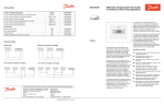
A number of DIL switches on the rear of the unit allow the installer to make some basic hardware settings. The diagram below details the selection options:
Programmable
*
unit must be programmed
before this switch is set to
disable
HC models*
HP models*
Non-Programmable
HCT models*
HPT models*
1
Software Settings
The 8000 Series incorporates a wide range of installer configurable options which are selected
from within an advanced programming mode. A brief description of the options is listed below:
Option
Description
Factory setting
Other options
1
Temperature override timer
Next event
1,2,3 or 4 hours or disabled
2
Fan run-on after cooling timer
Off
30, 60 or 90 Seconds
3
Fan operating mode setting
All
Smart fan (LOC)
4
Heat / Cool dead-band setting
2°C
1,3 or 4°C
5
Limit maximum heating set-point
adjustment
30°C
Can be reduced to 6°C in
0.5°C steps
6
Limit minimum cooling set-point
adjustment
16°C
Can be increased to 40°C
in 0.5°C steps
7
Limit minimum heating set-point
adjustment
6°C
Can be increased to 30°C
in 0.5°C steps
8
Limit maximum cooling set-point
adjustment
40°C
Can be reduced to 16°C
in 0.5°C steps
9
Thermostat calibration
0°C
±1.5°C
2 min Off,
6 cycles per hour
2 min On/Off, 6 cycles
4 min On/Off, 1 cycle per
hour selection or 4 min On/
Off, 3 cycles per hour
HP8000 Heat-Pump Models Only
A
Compressor delay timer
b
This option not used
C
Heat-pump low cut-off adjustment
(Active only if outdoor sensor is
detected)
-9°C
-30°C to +15°C in
1°C steps
d
Heat-pump balance point
adjustment.
(Active only if outdoor sensor
is detected)
10°C
0°C to 21°C in
1°C steps
HC8000 Heat/Cool Models Only
A
Cooling source type selection
Compressor, CP YES
Chilled water source
CP NO
b
Thermostat cooling stage cycle
rate per hour setting. (Only
available if ”CP No” is selected
in A above)
6 cycles per hour
3 cycles per hour
C
Thermostat heating stage
cycle rate per hour setting.
6 cycles per hour
3 cycles per hour
d
Heating stage integral action
time selection
5%
2.5% or 10%
All Models with Remote Room Sensor/Duct Sensor
E
Disable remote sensor option.
(Only active if a remote room or
duct sensor is detected)
Remote sensor
enabled
Remote sensor
disabled
Software version number - please interrogate unit in “Advanced Programming mode”
Service Mode
2
In addition to advanced programming settings, the thermostat also incorporates a service mode
which allows the installer to manually sequence the heat/cool and fan stages during system
commissioning.
Specification
Temperature range
Heating, off 6-30oC, (43-86°F ), Cooling, 26-40oC (61-104°F), off
Thermal differential
< 1oC (2°F)
Dead zone options
1-4oC (2-10°F), selectable by installer
Programming options*
All models can be set for 24hr, 5/2 or 7 day operation by
installer
Programmed events per day*
2 or 6 selectable by installer, inc off events for both heat & cool
Vacation programming option
Up to 99 days, heat & cool set points can be set independently
Factory pre-set programmes
Yes, refer to user manual details
Control ouput
Pl algorythm with Chrono-proportional output with adjustable
cycle rate
Power supply
Battery powered
2 x AA batteries
24V power supply
20-30 Vac, 50/60 Hz
230V power supply
220/250 Vac, 50/60 Hz
Memory retention
Rechargeable battery for real time (48 hours whenfully
charged), non-volatile memory device for all other settings
Fan mode options
Auto, On or Smart-Fan (fan on during day & Auto during night)
User mode selection
Heat/cool models
Heat/Cool/Auto/Off and holiday and thermostat mode
Heat pump models
Heat/Cool/Auto/Off plus emergency heat, holiday and
thermostat mode
Output relay voltage rating
10-240 Vac
Output relay current rating
2 (1) Amp per relay, min. 10mA
Output relay number & contact type
Varies according to model, refer to installation guide
Installer DIL switch settings
Yes, refer to commissioning guide
Installer advanced programming
settings
Yes, refer to commissioning guide
Installer service mode option
Yes, refer to commissioning guide
Compressor delay timer
Yes , all compressor stages, adjustable
Reversing valve control, HP models
Yes, selectable “O” or “B” function with SPDT output controls
Heat pump balance point control
Yes, programmable high and low balance points (outdoor
sensor required)
Lockable keypad
Electronic keypad lock, plus mechanical locking catch on cover
flap
Limitation of high and low set points
Both heat and cool ranges can be limited or locked
Limitations of temperature override
Can be limited to +/- 2oC (3°F) or disabled
Temperature Override
Can be limited to “next event”, 1, 2, 3, or 4 hrs disables
Max ambient temperature
45oC (113°F)
Dimensions (mm)
137 wide x 117 high x 25 deep
* Programmable models only
Ordering Details
Function
Programmable
230volt
087N681800
24 volt
HC8111-1
087N680700
087N690700
HC8111-3
087N690600
087N681900
HC8221-1 087N680800
Battery
1 Heat, 1 Cool
HC8113-1
HC8110-1
087N680300
HC8113-3
2 Heat, 2 Cool
HC8223-1
HC8110-3
087N690500
HC8223-3
087N691000
HC8221-3 087N690900
HC8220-3 087N690800
2 Heat, 1 Cool (Heat Pumps)
HP8213-1
087N682000
HP8211-1
087N680900
HP8210-1
087N680500
3 Heat, 2 Cool (Heat Pumps)
HP8323-1
087N682100
HP8321-1
087N681000
HP8320-1
087N680600
HC8220-1 087N680400
Non-Programmable
230volt
24 volt
Battery
1 Heat, 1 Cool
HCT8113-1 087N691900 HCT8111-1 087N681400
HCT8113-3 087N694500 HCT8111-3 087N694700
HCT8110-3 087N694800
2 Heat, 2 Cool
HCT8223-1 087N692100 HCT8221-1 087N681500
HCT8220-1 087N691200
HCT8223-3 087N695300 HCT8221-3 087N695500
HCT8220-3 087N695600
2 Heat, 1 Cool (Heat Pumps)
HP8213-1
087N692300 HPT8211-1 087N681600
HPT8210-1 087N691300
3 Heat, 2 Cool (Heat Pumps)
HP8323-1
087N692500 HPT8321-1 087N681700
HPT8320-1 087N691400
Accessories
HCT8110-1 087N691100
(1) All models can use 4 sensor units for temperature averaging (2) Maximum sensor cable length 50m
Remote room sensor unit (1), (2)
TS2
087N681100
Duct mounting sensor (2)
TS5
087N681200
Outdoor sensor (2)
TS6
087N681300
3
Application Examples
Heat Pump Applications with 1 heat
and 1 cool stage from compressor
plus auxilliary heat stage using
HP8000 & HPT8000 models
System in heating mode
System in cooling mode
HP8210-1, HP8211-1, HP8213-1
Notes:
1) 24 volt and 230 volt versions only.
On 24 volt models, power supply is 24 volts AC.
On 230 volt models, power supply is 230 volts AC.
2) Y2 and W2 only on 2 heat/2 cool models.
4
Heat/Cool Systems with 1 stage
outdoor unit and 1 stage heat from
warm air system, using HC8000 &
HCT8000 models set for auto
change-over.
HEATER
HC8110-1, HC8111-1, HC8113-1
Notes:
1) 24 volt and 230 volt versions only.
On 24 volt models, power supply is 24 volts AC.
On 230 volt models, power supply is 230 volts AC.
2) Y2 and W2 only on 2 heat/2 cool models.
5
2 Pipe Heat/Cool System using
HC8000 & HCT8000 models set to
manual change-over
Note: Central system delivers hot water during winter and chilled water in summer.
HC8110-1, HC8111-1, HC8113-1
Notes:
1) 24 volt and 230 volt versions only.
On 24 volt models, power supply is 24 volts AC.
On 230 volt models, power supply is 230 volts AC.
2) Y2 and W2 only on 2 heat/2 cool models.
6
4 Pipe Heat/Cool System using
HC8000 & HCT8000 models set to
auto change-over
Note: Central system delivers both hot and cold water all year round.
HC8110-1, HC8111-1, HC8113-1
Notes:
1) 24 volt and 230 volt versions only.
On 24 volt models, power supply is 24 volts AC.
On 230 volt models, power supply is 230 volts AC.
2) Y2 and W2 only on 2 heat/2 cool models.
7
Sensor Averaging
Using 4 sensors, wired as shown,
temperature averaging can be achieved.
8000 Series Thermostat
Remote
Sensor
13 15
Danfoss Randall can accept no responsibility for possible errors in catalogues, brochures and other printed material, and reserves the right to alter its products without notice.
This also applies to products already on order provided that such alterations can be made without subsequent changes being necessary in specifications already agreed.
Danfoss Randall Ltd
Ampthill Road
Bedford, MK42 9ER
Tel: 01234 364621 Fax: 01234 219705
Email: [email protected]
Website: www.danfoss-randall.co.uk
8
Part No 472 Iss 2 01/03