1
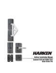
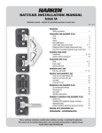
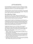
BATTCAR SWITCH SYSTEM
INSTALLATION MANUAL
26 mm, 32 mm
Installation Manual – Intended for specialized personnel or expert users
4677 12/13
Introduction
Safety precautions
2
Preassembly
Tools
2
Parts3-4
Sizing
5
Track length/switch height considerations
5
Track length
6
Mounting track and switch
7
Mounting track to mast
7
Assembly
Install track (general instructions)
Mounting switch
Mounting storage track Mounting gate track
Mounting standard/high-load track
Mounting top track
7
8
9
9
10
10
Commissioning
Loading cars on track
Loading headboard
Removing toggle from cars
11
12
13
Operation
Raising sail
13
Sailmaker’s Instructions
Dimensions14
Installing headboard car assembly
14
Distance between attachment points
15
Setting reef points
15
Trysail Switch System
Preassembly16
Installing track
16
Loading cars
16
Sailmakers’s instructions
16
Replacement parts
17 - 18
Troubleshooting/inspection/maintenance/warranty19
Please read these instructions carefully before installing, servicing, or operating the equipment.
This manual may be modified without notice. See: www.harken.com/manuals for updated versions.
PLEASE SAVE THESE INSTRUCTIONS
Introduction
This manual gives technical information on installation and service. This information is destined exclusively
for specialized personnel or expert users. Installation, disassembling, and reassembling by personnel who are
not experts may cause serious damage to property or injury to users and those in the vicinity of the product.
If you do not understand an instruction contact Harken.
The user must have appropriate training in order to use this product.
Harken accepts no responsibility for damage or harm caused by not observing the safety requirements and
instructions in this manual. See limited warranty, general warnings, and instructions in www.harken.com/manuals.
Purpose
Harken battcars are designed to reduce the size of or completely drop the mainsail on a sailboat so wind has little
effect on the sail. Use of this product for other than normal sailboat applications is not covered by the limited warranty.
Safety Precautions
WARNING! This symbol alerts you to potential hazards that may kill or hurt you and others
if you don't follow instructions. The message will tell you how to reduce the
chance of injury.
CAUTION! This symbol alerts you to potential hazards that may hurt you and others if
you do not follow instructions. The message will tell you how to reduce the
chance of injury.
WARNING! Strictly follow all instructions to avoid potential hazards that may
kill or hurt you and others. See www.harken.com/manuals for general warnings
and instructions.
Tools
4
2
1
3
8
9
6
1.Tape measure
2. Power drill
3. Drill bits
4. Hammer
5. Plastic hammer
6. Hacksaw
7. Transfer punch
2
7
11
10
  8. Tape
  9. File
10. Hex key
11. McLube™ Sailkote™
12. Tap for mast mounting holes (not shown)
Threadlocking adhesive for mast screws
26 mm/32 mm Battcar Switch System
07/14/11
PreassemblyParts
Intermediate car
Tack car
HC7493
HC7322
HC8125
HC8099
Trysail car
HC9045
HC9046
Reef car 26 mm
Reef car 32 mm
C9342
C9494
Headboard car
(assembly)
HC7325
HC8076
Batten car with
threaded stud
HC7324
HC8098
HC7316
C7814
3876
Web-on
standard
Main Components
Part No.
Description
System
Comments
HC9045 Headboard car
Must use 3876 or 3877 headboard.
HC7493 Intermediate car
Consult sailmaker for quantity required.
HC7324 Batten car
HC7325 Reef car
HC8125 Tack car
C9494
Trysail car
HC9046 Headboard car
26 mm
12mm Threaded stud. Purchase batten receptacle separately.
Use to secure tack when reefing.
Use with halyard lock to tension luff.
Use with trysail switch.
Must use 3876 or 3877 headboard.
HC7322 Intermediate car
HC8098 Batten car
12mm Threaded stud. Purchase batten receptacle separately.
HC7316 Batten car
32 mm 14mm Threaded stud. Purchase batten receptacle separately.
HC8076 Reef car
HC8099 Tack car
C9342
Trysail car
Use to secure tack when reefing.
3877
Web-on
square top
Use with halyard lock to tension luff.
Use with trysail switch.
Headboard Plates
3876
3877
11/24/10
26 mm
See sailmaker instructions.
32 mm
Square top web-on headboard
See sailmaker instructions.
Standard web-on headboard
26 mm/32 mm Battcar Switch System
3
PreassemblyParts
C
B
Storage track
Storage track
HC8147
HC8148
HC8149
HC8150
Gate track
HC10060
HC8221
HC8226
Trysail switch
Endstop
1522A
548A
Splice links
HC8222
HC8227
11/32"
26
26mm
mm
A
/32" (4 mm)
5
5
/8"
16 mm
HC8147 HC8148
HC7466 HC8221
11/32"
26 mm
/32" (4 mm)
5
/8"
16 mm
5
HC10060
311/16"
93.3 mm
D
11/4"
32 mm
1/4"
6 mm
Track switch
13/16"
20 mm
HC8149 HC8150
HC7391 HC8226
C9341 C9342
C9492 C9493
T-Track, Splice Links and Enstops
Part
No.
Description
Length
in
mm
Width
in
mm
Height
in
mm
Weight
oz
g
Fasteners
in
mm
Fastener
spacing
mm
26 mm
1181/8
78 3/4
—
25/32
3000
2000
—
55
11/32
11/32
11/32
117/32
26
26
26
39
/8
/
—
—
16
16
—
—
61.1
40.3
0.1
—
1736
1141
3
—
/4
/
—
—
6
6
—
—
75
50
—
—
HC7391 3m T-Track
1181/8
HC8880 2m T-Track/high-load
78 3/4
HC8227 Splice link
—
548A
Endstop
227/32
*Includes spacer tube for cutting adapters. See page 7.
3000
2000
—
72
11/4
11/4
—
21/32
32
32
—
52
13 16
/
/
—
—
20
20
—
—
96.2
63.1
0.2
—
2734
1790
5
—
5 16
/
/
—
—
8
8
—
—
75
50
—
—
HC7466
HC8879
HC8222
1522A
3 m T-Track
2 m T-Track/high-load
Splice link
Endstop
5
5 8
1
1 4
32 mm
13 16
5 16
HC8220 26 mm
HC7382 32 mm
Switch, Storage and Gate Track
Part
No.
Description
Length
(A)
in
mm
Width
(B)
in
mm
Switch Width
(C)
in
mm
Height
(D)
in
mm
Weight
oz
g
Fasteners
in
mm
Fastener
spacing
mm
26 mm
251/4
1911/16
2817/32
2817/32
1113/16
641
500
725
725
300
4
11/32
11/32
311/16
11/32
102
26
26
93.3
26
4
—
—
—
—
102
—
—
—
—
5 8
HC7382 Switch
281/2
HC8149 800 mm Storage track
311/2
HC8150 1025 mm Storage track
4011/32
HC8226 Gate track
1113/16
Trysail Switch C9340, C9341, C9492, C9493 Trysail Tracks – See page 16
724
800
1025
300
5
11/4
11/4
11/4
127
32
32
32
5
—
—
—
127
—
—
—
13 16
HC8220
HC8147
HC8148
HC10060
HC8221
Switch
500 mm Storage track
725 mm Storage track
725 mm Double storage track
Gate track
/
/
5/8
5
/8
5/8
16
16
16
16
16
43.1
10.2
14.8
57.2
6.1
1225
291
419
1623
174
1 4
/
/
13
/16
13/16
20
20
20
20
72.8
25.6
32.8
9.6
2068
728
933
273
5 16
5 8
/
/
1/4
1
/4
1/4
6
6
6
6
6
—
50
50
50
75
/
/
5
/16
5/16
8
8
8
8
—
50
50
75
1 4
32 mm
4
26 mm/32 mm Battcar Switch System
13 16
5 16
11/24/10
PreassemblySizing
Sizing
Make sure you have the correct size battcar system for your boat.
System
Fits Boats
Minimum
Maximum
Part No.
Headboard Car
Part No.
Battcar
Part No.
Intermediate Car
Part No.
Reef Car
Part No.
Tack Car
26 mm
50 ft (15.2 m)
80 ft (24 m)
HC9045
HC7324
HC7493
HC7325
HC8125
32 mm
80 ft (24 m)
130 ft (40 m)
HC9046
HC8098, HC7316
HC7322
HC8076
HC8099
Track length and switch
height considerations
Switch height is determined by the
number of cars required for system
and the length of the storage track.
Note: Cars will pass each other when
top of car is at “A” distance above
bottom of switch. See chart at right.
A
Unit
in
mm
26 mm
3.94
100
32 mm
6.44
163
A
12"
305 mm
3852
Make sure track is longer than sail luff
to allow for stretch as sail ages. Track
must not block halyard exit. Using
gate track above switch allows
bottom storage track to extend
down to gooseneck.
03/30/09
26 mm/32 mm Battcar Switch System
5
Preassembly
Track Length
Layout system using charts to plan track location and lengths.
A
Variable-Length Top Track (26/32 mm Systems)
Length
Hole Spacing
mm
in
mm
75
If possible use a storage track with holes drilled for endstops
positioned at the upper end for top endstop.
B
Standard Track (26/32 mm Systems)
Length
mm
in
3000
118.11
Total track length ___________
- SUM ___________
Top track length A _ __________
Hole Spacing
mm
75
X
Length
C
High-Load Track (26/32 mm Systems)
Length
mm
in
2000
78.74
Place in reefed headboard areas.
=
Quantity
+
Hole Spacing
mm
50
X
Length
C1
Trysail Switch—26mm System
Length
mm
in
368
14.50
Trysail Switch—32mm System
Length
mm
in
406
16.00
D
Gate Track—26/32 mm Systems
Length
Hole Spacing
mm
in
mm
300
11.81
75
Removable track - Allows cars to be left attached to sail and removed
from top of switch.
E
Switch—26mm System
Length
mm
641
Switch—32mm System
Length
mm
724
in
25.24
—
—
—
in
28.50
—
—
—
Storage Track—26 mm System
Length
mm
in
500
19.69
F
6
Hole Spacing
—
mm
Variable
Hole Spacing
—
mm
Variable
725
28.54
Storage Track—32 mm System
Length
mm
in
1
=
50
Hole Spacing
mm
31.50
50
1025
40.35
50
+
Quantity
1
=
+
Quantity
+
1
=
Quantity
+
Hole Spacing
mm
50
800
26 mm/32 mm Battcar Switch System
=
Quantity
1
=
Quantity
SUM
Enter “SUM” above to
calculate “Top track length.”
11/24/10
Preassembly
Mounting Track and Switch
Note width and shape of switch and
build a platform on mast for mounting.
If using two storage tracks, make sure
switch and storage tracks are on the
same flat surface. Curved mast surfaces
will not allow correct alignment.
HC10060 Double storage track for the
26 mm comes with a tube to cut spacers
to adapt to curved mast surfaces.
Note: when mounting to curved surfaces,
wedges will be necessary under the switch.
Wedge
Wedge
HC10060 Double storage
track for 26 mm
Preassembly
Mounting Track to Mast
Consult with mastbuilder. Use suitable
reinforcing plates when fastening track
to carbon spars.
Assembly
General Instructions
When mounting tracks work meticulously using a straight edge reference line along mast. Do not let tracks vary
from this line. Tape track in place and centerpunch hole at bottom using a transfer punch.
Tip for mounting to aluminum mast: Use low speed drill with tap for cutting threads.
IMPORTANT! Use blue Loctite® instead of oil to lubricate tap.
Remove track and drill and tap single hole.
Fasten track using this single screw and align
side to side correctly. Use tape to hold in
place. Use longer car to test alignment.
Move up several holes and use transfer
punch to mark a second hole. Remove track
and drill and tap hole.
Fasten track using two screws. Mark all
remaining holes using punch. Remove track
and drill and tap all holes. Before installing
track make sure upper end has splice piece
inserted.
Use threadlocking adhesive to secure screw.
See instructions that begin on
page 8.
11/21/11
26 mm/32 mm Battcar Switch System
7
Assembly
Mounting Switch
Insert three splice links into switch track.
Using a plastic hammer, tap them in place.
Carefully align track and tape in place.
Use a transfer punch to mark a single
hole.Remove and drill and tap. Fasten
with single screw, no adhesive.
Re-align and mark a second hole using
transfer punch. Screw to mast using two
screws, no adhesive.
Mark remaining holes using transfer punch.
Remove and drill and tap remaining holes.
Mount switch to mast using threadlocking
adhesive on screws as required.
8
26 mm/32 mm Battcar Switch System
07/21/11
Assembly
Mounting Storage Tracks
Make sure storage track ends with holes
for endstop are at bottom. If shortening
is required, cut track from upper end
maintaining holes for endstop.
Fix bottom loader tracks by placing track
over splice and tapping into place using
plastic hammer.
Align track and tape in place. Use transfer
punch to mark hole. Remove track, drill
and tap. Fasten track using single screw.
Center punch another hole, drill, tap and
fasten track. Center punch remaining holes,
drill, tap and install using threadlocking
adhesive.
Assembly
Mounting Gate Tracks
With gate track off mast, use plastic hammer
to tap splice link into upper end of track.
Carefully align track. Use transfer punch
to mark holes. Drill, tap and mount as
directed above.
IMPORTANT! Do not use threadlocking
adhesive on screws because gate track
is removed for loading cars.
07/21/11
26 mm/32 mm Battcar Switch System
9
Assembly
Mounting Standard/High-Load Tracks
With track off mast, tap upper splice link
into track using procedures outlined above.
Follow general instructions, page 7,
with regard to drilling and taping a
single hole, etc. Always make sure
to keep tracks aligned.
Assembly
Mounting Top Track
If possible use a storage track with holes
drilled for endstops positioned at the upper
end for top endstop.
10
26 mm/32 mm Battcar Switch System
03/30/09
Commissioning
Load Cars on Track
Remove gate track.
Install cars from above switch.
Lubricate cars onshore before loading.
Before bringing headboard assembly or cars
onboard boat, spray underbody track slot
(see arrows above) with a light coating of
McLube™ Sailkote™.
WARNING! Overspray from McLube
will cause slippery decks which may
result in loss of footing. Cover decks
or spray cars off boat.
Note: Mustard-colored pegs on foot of car
guide it to correct side. Car will go to side
of track where there are no pegs.
Tip:
Plain foot to right, car goes to right.
Plain foot to left, car goes to left.
03/21/12
26 mm/32 mm Battcar Switch System
11
Commissioning
Loading Headboard
Headboard cars have spherical bearings
and are designed to run through switch.
Both cars must run through same side
of switch. Make sure cars are loaded
with pegs on same side.
12
26 mm/32 mm Battcar Switch System
03/30/09
Commissioning
Removing Toggle From Cars
When removing parts, make sure you
retain plastic bushings between vertical
pin and hole in car tangs.
Operation
Raising Sail
When raising, lowering, or reefing sail make
sure sail is not loaded and cars pass
through switch easily. Watch sail and cars
carefully and stop hoisting immediately if any
binding is detected.
Possible sources of binding:
Cars bind at switch
Reef line binds on fingers
Reef line binds between car and switch
Headboard or battens bind on lazy jacks
Battens have draped off boom, leveraging car
Correct the binding problem or luff sail before
resuming hoist. If forced, the fingers that
extend into switch may be damaged, requiring
expensive switch and car replacement. Lazy
jacks may also be damaged.
IMPORTANT! When using an electric halyard
winch, be especially vigilant when raising
sail. Luff sail. Watch for any binding or
jamming at the switch and stop hoist
immediately if any occurs.
If winch operator does not have a good view of
switch cars, station a crewmember with a good
view and communication to operator.
If there is a jam, damage to switch and cars
will occur very quickly resulting in expensive
repairs unless hoisting is stopped.
IMPORTANT! Make sure reef outhaul loads
are not applied to cars when in switch.
Damage to switch and cars will occur,
resulting in expensive repairs.
07/21/10
Important
Watch for binding at
switch. Stop hoisting
immediately.
26 mm/32 mm Battcar Switch System
13
Sailmakers Instructions
Dimensions
B
C
F
E
B
D
G
A
A
Batten car
D
A
C
32 mm Reef car
C
Headboard car
assembly
B
(Headboard not
included)
A
D
B
C
D
Intermediate car
26 mm reef car
in
mm
in
mm
in
mm
in
mm
in
mm
in
mm
G
Stud Ø
mm
Headboard car assembly
Intermediate car
Batten car
Reef car
Tack car
105/8
23/8
215/16
317/32
317/32
270
60
75
90
90
17/16
17/16
17/16
17/16
17/16
37
37
37
37
37
127/32
127/32
127/32
127/32
47
47
47
47
35/8
13/16
—
1
1
92
21
—
25
25
—
—
229/32
—
—
—
—
73
—
—
—
—
41/16
—
—
—
—
103
—
—
—
—
12
—
—
Headboard car assembly
Intermediate car
Batten car/12mm stud
Batten car/14mm stud
Reef car
Tack car
11
215/16
317/32
317/32
417/32
417/32
280
75
90
90
115
115
17/8
17/8
17/8
17/8
17/8
17/8
47
47
47
47
47
47
23/8
—
—
23/8
23/8
60
—
—
60
60
315/16
1
—
—
1
1
100
25
—
—
25
25
—
—
37/16
37/16
—
—
—
—
87
87
—
—
—
—
419/32
421/32
—
—
—
—
117
118
—
—
—
—
12
14
—
—
A
Part
No.
Description
B
C
D
E
F
26 mm
HC9045
HC7493
HC7324
HC7325
HC8125
32 mm
HC9046
HC7322
HC8098
HC7316
HC8076
HC8099
Sailmakers Instructions Installing Headboard Car Assembly
Use 13/4" (45 mm) webbing. Holes in
headboard accept 416 16 mm cheek
blocks for leech line. Use 4 mm
x 10 mm fasteners.
If more reinforcement is necessary,
web through lightening holes.
3876
System
26 mm
3876
Web-on
standard
3877
Web-on
square top
3877
in
mm
in
mm
A
57/16
138
53/4
146
B
29/32
58
29/32
58
A
53/4
146
61/16
154
B
219/32
66
219/32
66
B
B
14
A
3852
32 mm
A
26 mm/32 mm Battcar Switch System
03/30/09
Sailmakers Instructions
Slug-/Drill/Tap Mount
Distance Between Attachment Points
DIAGRAM A
Battens and intermediate cars placed at sailmaker's discretion.
Maximum distance between attachment points is 4' to 4'6"
(1.2 m to 1.35 m).
Distance may be slightly greater. Contact Harken to discuss sail
reshaping to eliminate luff flutter.
Note: Adding battens may reduce stack height by eliminating
luff cars.
CORRECT
INCORRECT
DIAGRAM B
While sailing
Setting Reef Points
loaded cars
must not ride
Space reef points halfway between sail attachment points. Battens or reef
in this area.
points may need to be moved. See Diagram A above.
Note: Batten fittings and cars cannot handle reefing outhaul or downhaul
loads. Transfer loads to a tack fitting. See Diagram B above.
IMPORTANT! When setting up reef, make sure cars are not loaded when
they are in the switch area. If reef outhaul loads are applied to switch,
the switch and cars will be damaged resulting in expensive repairs.
Instruct operators to not raise or lower sails with high loads on the cars
while in the switch area.
Harken is not responsible for damage to the switch area due to reef loads
or raising or lowering a sail when the sail is loaded.
08/19/10
26 mm/32 mm Battcar Switch System
15
Trysail Switch System
Length
in
mm
in
mm
oz
g
141/2
141/2
23/8
368
368
60
425/32
425/32
11/32
121
121
26
27
27
5
762
762
143
6
6
—
—
—
1001
—
—
454
C9341
Port trysail switch*‡
16
406
C9340
Starboard trysail switch*‡
16
406
75
C9342
Car body*‡
215/16
*Available in black or clear anodized ‡Allow 8 weeks lead time
57/8
57/8
31/32
149
149
77
43
43
11
1222
1222
309
8
8
—
—
—
595
—
—
270
Description
Width
Weight
Maximum
working load
lb
kg
Fasteners
mm
Part
No.
26 mm
C9493
C9492
C9494
Port trysail switch*‡
Starboard trysail switch*‡
Car body*‡
32 mm
Trysail car
Preassembly
Use standard track and bend to transition
between side tracks and switch. The cars
should not be under load in this section.
Installer is responsible for determining
thebend of the track. A compound bend
isrequired to transition from the side of
themast to the aft face.
IMPORTANT! Special care must be taken so
that the trysail or standard cars do not hit
the adjoining track.
Trysail switch
Guide pins
C9493
C9492
C9341
C9340
C9342
C9494
Installing Track
Consult with mast builder. Use suitable
reinforcing plates when fastening track
to carbon spars.
Load cars with guide pins on the same side
as the trysail storage track. If storage track
is on the starboard side, make sure pins
are on starboard side when loading onto
track.
Sailmaker instructions
Place cars so that there are none in the
special compound bend track section or
switch. Cars placed in this area under
load will damage fingers of switch.
16
Trysail storage
track
26 mm/32 mm Battcar Switch System
Main
track
No load in this area of trysail track
Loading Cars
07/20/11
Replacement Parts
HC9045—26 mm System
Part No.
Description
Quantity
1
HC9045
Coupler assembly
1
a
MS-292
Smalley ring
2
b
MS-284
Cup
4
c
MS-285
Spherical becket
2
d
AL-2037
Coupler only
1
2
H-37545A
Clevis pin
1
3
HFS203
Cotter pin
1
4
HFS1146
M8 x 52 SHCS
2
5
8
H-46463
Igus® bushing
6
HFS920
M8 lock nut
2
Car assembly with
7
H-43304
2
sliders and pins
8
H-31089A
Guide pin
4
*8 more are listed in bill. They are used to hold
non-replaceable insert bearing in place.
3
1
a
b
c
2
b
d
4
5
6
7
8
1
a
b
c
d
e
1
3
a
b
c
b
d
e
2
4
5
6
8
2
3
4
5
6
7
8
9
HC9046—32 mm System
Part No.
Description
HC9046NP
Coupler assembly
MS-291
Smalley ring
MS-288
Cup
MS-287
Spherical becket
AL-2047
Coupler only
MS-265
Igus® bushing
H-37545A
Clevis pin
HFS203
Cotter pin
H-36101A
M10 x 68 SHCS
HCP1730
Igus® bushing
HFS191
Flatwasher
HFS920
Thin lock nut
Contact Harken Car body
H-37242A
Guide pin
Quantity
1
2
4
2
1
2
1
1
2
4
2
2
2
4
7
9
03/21/12
26 mm/32 mm Battcar Switch System
17
Replacement Parts
HC7324
HC8098
HC7316
C7814
Part No.
Part No.
Part No.
Part No.
H-37359A H-47961 H-47960 H-39218A
HCP1724 MS-1028 HCP704 HCP1819
HFS1146 H-36101A H-36101A H-48140
—
H-37226A H-37226A
—
HCP1739 HCP1730 HCP1730 HCP1819
HFS920
HFS920
HFS920
HFS937
H-43303
Contact Harken
H-31089A H-37242A H-37242A H-41991
1
1a
2
3
4
5
6
6a
1
Description
Toggle/stud assembly w/bushing
Igus® bushing only
Socket head cap screw
Delrin® washer
Igus® bushing
Lock nut
Car assembly/sliders/guide pins
Guide pin only
1a
2
3
3
2
1
4
Quantity
1
2
1
2
2
1
1
2
4
3
5
5
3
7
6a
1
2
3
4
2
1
2
3
4
5
6
HC7325
Part No.
HFS1146
HCP1739
H-40902
HFS920
H-43304
H-31089A
Description
Socket head cap screw
Igus® bushing
Bushing/becket roller
Lock nut
Car assembly/sliders/guide pins
Guide pin only
Quantity
1
2
2
1
1
2
HC8125
Part No.
H-40900
HCP1739
H-40902
HFS920
3
HC8099
Part No.
H-40891
HCP1730
H-36138A
HFS920
3
Quantity
1
2
2
1
4
5
1
6
2
2
Description
Socket head cap screw
Igus® bushing
Bushing/becket roller
Lock nut
4
1
3
4
5
6
7
1
5
8
6
1
2
3
4
5
5a
18
HC7493
Part No.
HCP1739
H-37250A
H-32605A
HFS920
H-43305
H-37089A
HC7322
Part No.
HCP1730
H-36101A
H-36138A
HFS1586
Contact Harken
H-37242A
Description
Igus® bushing
Socket head cap screw
Bushing/becket roller
Lock nut
Car assembly/sliders/guide pins
Guide pin only
Quantity
2
1
1
1
1
2
26 mm/32 mm Battcar Switch System
1
2
3
4
5
6
7
HC8076
Part No.
H-40891
HFS130
HCP1730
H-36138A
HFS191
HFS920
H-37242A
Description
Quantity
Socket head cap screw M10X107
1
Flat washer 10 mm
1
4
Igus® bushing
Bushing/becket roller
2
Flat washer 8 mm
1
Lock nut
1
Guide pin only
2
12/03/13
Troubleshooting
Operation
Problem
Probable Cause
Solution
Slider damaged or missing.
Check and/or replace slider.
Dirt in cars.
Use detergent and fresh water to flush dirt out of
cars; move cars up/down do circulate; follow with
high pressure water; clean track grooves.
Stud threaded too tightly into receptacle.
Back off threaded stud two turns.
Car loaded with guide pins on wrong side.
Check direction car is loaded.
Can't raise sail, cars stop at switch.
Car loaded upside down. Pins in car on wrong side.
Remove car, flip it around and reload.
Nut on battcar is not holding.
Lock nut has been used too many times.
Get new 6 mm lock nut.
Batten receptacle does not rotate.
Nuts are too tight.
Loosen nuts slightly.
Cars jam when raising sail.
Headboard or cars are catching on lazy jacks.
Use topping lift or rod vang and shock cord to pull
lazy jacks out to shrouds.
Sail will not go all the way up.
Sail is too tall or sheave is too far forward.
Have sail shortened or move sheave aft.
Vertical post or pin on batten receptacle bending.
Reef loads are being transferred to batten receptacle.
Transfer reef downhaul and outhaul loads to mast
or boom gooseneck.
Reef tack fitting will not reach reef hook.
Reef point too close to sail attachment.
Move intermediate car sail attachment.
Cars bind.
Delrin® is a registered trademark of E. I. du Pont de Nemours and Company or its affiliates.
Igus® is a legally registered trademark of Igus® GmbH and/or Igus® Inc.
Loctite® is a registered trademark of Henkel AG & Company KGaA.
Inspection
Inspect parts periodically and especially before long passages. Check for loose nuts, cotter pins or track screws.
Check toggles or batten threaded studs for wear. If parts are under load during long passages it is important to
inspect them carefully while in use.
WARNING: Parts degrade over time and may become weak. Failure to inspect and correct may result
in system jamming or breaking under load.
Maintenance
Harken equipment is designed for minimal maintenance, but some maintenance is required for optimum and safest
possible operation and to comply with the Harken limited warranty. In general, the most important aspect of
maintenance is to keep your equipment clean by frequently flushing with fresh water.
In corrosive atmospheres, stainless parts may show discoloration around holes, rivets and screws. This is not serious
and may be removed with a fine abrasive.
With the exception of winches, do not use grease unless specifically recommended in the instruction sheet.
Flush blocks thoroughly with fresh water. Periodically, disassemble the blocks and clean with detergent
and fresh water.
IMPORTANT! Exposure to some teak cleaners and other caustic solutions can result in discoloration of part
and is not covered under the Harken warranty.
Warranty
For additional safety, maintenance and warranty information see www.harken.com/manuals or the Harken catalog.
03/22/12
26 mm/32 mm Battcar Switch System
19
Corporate Headquarters
N15W24983 Bluemound Rd, Pewaukee, WI 53072 USA
Telephone: (262) 691-3320 • Fax: (262) 701-5780
Web: www.harken.com • Email: [email protected]
Harken Australia Pty, Ltd.
1B Green Street, Brookvale, N.S.W. 2100, Australia
Telephone: (61) 2-8978-8666 • Fax: (61) 2-8978-8667
Web: harken.com.au • Email: [email protected]
Harken France
ZA Port des Minimes, BP 3064, 17032 La Rochelle Cedex 1, France
Telephone: (33) 05.46.44.51.20 • Fax: (33) 05.46.44.25.70
Web: harken.fr • Email: [email protected]
Harken Italy S.p.A.
Via Marco Biagi, 14, 22070 Limido Comasco (CO) Italy
Telephone: (39) 031.3523511 • Fax: (39) 031.3520031
Web: harken.it • Email: [email protected]
Harken New Zealand, Ltd.
158 Beaumont Street, Westhaven, P.O. Box 90689, Victoria St. West, Auckland 1142, New Zealand
Telephone: (64) 9-303-3744 • Fax: (64) 9-307-7987
Web: harken.co.nz • Email: [email protected]
Harken Polska SP ZOO
ul. Rydygiera 8, budynek 3A, lokal 101, I piętro, 01-793 Warszawa, Poland
Tel: +48 22 561 93 93 • Fax: +48 22 839 22 75
Web: harken.pl • Email: [email protected]
Harken Sweden AB
Main Office and Harken Brandstore: Västmannagatan 81B
SE-113 26 Stockholm Sweden
Telephone: (46) 0303 61875 • Fax: (46) 0303 61876
Mailing address: Harken Sweden AB, Box 64, SE -440 30 Marstrand
Web: harken.se • Email: [email protected]
Harken UK, Ltd.
Bearing House, Ampress Lane, Lymington, Hampshire S041 8LW, England
Telephone: (44) 01590-689122 • Fax: (44) 01590-610274
Web: harken.co.uk • Email: [email protected]
Please visit: http://www.harken.com/locator.aspx
to locate Harken dealers and distributors
Printed in USA 4677 12/13