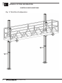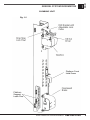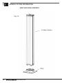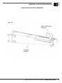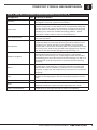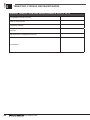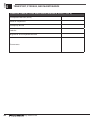
1
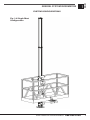
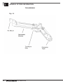
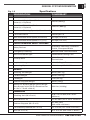
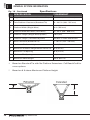
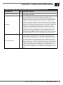
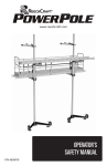
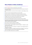
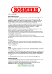
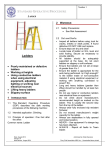
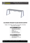
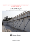
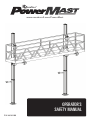
www.reechcraft.com/PowerMast
Operator’s
Safety Manual
P/N 4026288
GENERAL INFORMATION
www.reechcraft.com/PowerMast
© 2013 by ReechCraft Inc. All rights reserved
This manual may not be reproduced, photocopied, copied, duplicated or
translated without prior written consent from ReechCraft Inc.
This ReechCraft Inc. product is patented and protected in the United States
US Patent 6981573. All other US and International Patents Pending.
Using this product in methods not indented by ReechCraft Inc. are strictly
prohibited without prior written permission from ReechCraft Inc.
Product General Information:
Model – PowerMast
ReechCraft Inc.
474 45th Street South
Fargo, ND 58103
888-600-6160
www.reechcraft.com
2
by ReechCraft
GENERAL INFORMATION
REVISION LOG
Original Version of Manual........................................................June, 2013 v 1.0
TABLE OF CONTENTS
GENERAL INFORMATION.................................................................................. 4
WARRANTY................................................................................................. 4
SAFETY GUIDELINES......................................................................................... 5
SAFETY GUIDELINES................................................................................. 5
SECTION - 1 - GENERAL SYSTEM INFORMATION
System Configurations............................................................................... 7
Climbing Unit.............................................................................................. 9
Mast and Base Assembly..........................................................................10
Platform Support Assembly...................................................................... 11
Tie Assembly............................................................................................. 12
Specifications............................................................................................ 13
SECTION - 2 - LAYOUT PLANNING
Layout Plan................................................................................................ 16
Ground Preparation.................................................................................. 17
Tie Planning.............................................................................................. 17
SECTION - 3 - ERECTING THE SYSTEM
Pre-Assembly............................................................................................ 18
Erect Base Unit.......................................................................................... 20
Assemble Platform Support.................................................................... 22
Attach Platform......................................................................................... 24
Adding Height........................................................................................... 26
SECTION - 4 - POWER SYSTEM INSTALLATION
Power System Installation....................................................................... 30
Driver Installation..................................................................................... 30
Drill Installation......................................................................................... 31
Power Cord Installation............................................................................ 32
SECTION - 5 - OPERATING THE SYSTEM
Operating Work Platform......................................................................... 34
SECTION - 6 - TRANSPORT, STORAGE AND MAINTENANCE
Transport, Storage and Maintenance...................................................... 36
Inspection and Maintenance Logs.......................................................... 37
www.reechcraft.com/PowerMast
888-600-6160
3
GENERAL INFORMATION
WARRANTY
ReechCraft Inc., herein referred to as ReechCraft, warrants the PowerMast
System to be free from defects in materials and workmanship for a period of
one year after the date of initial purchase. Reechcraft’s obligation and liability
under this warranty are expressly limited to the repairing or replacing with
re-manufactured or new, at ReechCrafts option, any parts which appear to
have been defective in material or workmanship. Such parts shall be
provided at no cost to the distributor or end user.
All warranty claims require proof of original purchase and the serial number
of the product. If it is determined that the warranteed part needs expedited
service before ReechCraft or qualified distributor can inspect it, the customer
will be responsible for the cost of the part and will be credited back once the
original part has been returned to our manufacturing facility in Fargo, ND.
All returns must have a Return Merchandise Authorization or RMA. To obtain
a RMA, please call our customer service department at 1-888-600-6160.
In addition, please return your part prepaid, insured, and in a carton. Also
include your name, address, phone number, proof of purchase, and a brief
description of the problem. The address to return the part is: Reechcraft, Inc.,
Attention: Warranty Department, 1250 Homecrest Avenue, Wadena, MN 56482
USA
Our warranty does not cover wear and tear, misuse and/or abusive treatment.
Misuse may include, but is not limited to, damage by vehicles, tools, people,
animals, falling objects, acts of God, and using a PowerMast System in any
matter contrary to the warning/instruction labels and owner’s manual. If you
need an owner’s manual, please contact us or go to our website at www.
reechcraft.com.
This shall be in lieu of any other warranty, expressed or implied, including,
but not limited to, any implied warranty of merchantability or fitness for
a particular purpose. The liability of Reechcraft under this warranty shall
be limited solely to repair or replacement of the part on the Reechcraft
PowerMast System within the warranty period; and Reechcraft shall not be
liable, under any circumstances, for consequential or incidental damages,
including but not limited to, personal injury or labor costs. Some states do
not permit the exclusion or limitation of incidental or consequential damages,
so this exclusion may not apply to you. This warranty gives you specific
legal rights and you may have other legal rights, which may vary, from
state to state. This warranty is effective as of Jan 1, 2013. Manufacturing
specifications are subject to change without notice.
Under no circumstances will Reechcraft, Inc. be responsible for any expense
in connection with any repairs made by anyone other than the factory
or authorized service station unless such repairs have been specifically
authorized in writing by Reechcraft.
4
by ReechCraft
SAFETY PRECAUTIONS
SAFETY GUIDELINES
1. Safety comes first. To help ensure safety, always have a competent
person assemble, erect, operate, transport, store and maintain this
product. A competent person is defined as one who has the:
a. Ability to identify any present or foreseeable hazards;
b. Authority to take immediate corrective action;
c. Knowledge and training to assemble, erect, operate, transport,
store and maintain the system.
d. Operator’s manual available at all times.
e. Field experience to correctly assemble, erect, operate,
transport, store and maintain the system.
2. Be sure to follow all guidelines set forth in the operators manual for
proper assembly, erection, operation, transport, storage, and
maintenance.
3. Workers exposed to hazards are required to wear personal protection equipment such as hard hats, eye wear, gloves, safety boots as
prescribed by federal, state, and local authorities.
4. Make a layout plan for how your mast climbing work platform will be
used for the specific task. Examine the structure and ground conditions
where the system will be placed. On long walls, use multiple systems to
allow for more flexibility in access. Always position masts in a position
that provides a stable base and suitable connection to the structure.
5. Establish the distance of the platform to the wall or structure taking into
consideration wall offsets, curves, balconies, architectural features,
trees, wires, etc.
6. Be aware and refer to federal, state, and local guidelines for proper
distance away from non-system electrical lines.
7. Be sure the ground will support the bearing forces of the system in
accordance with this operators manual.
8. Always carry out maintenance and inspection as detailed in this manual
to help ensure system safety and efficiency. Be sure to manage all
jobsite inventory and ensure proper inspection and maintenance has
been conducted on all system components prior to use.
9. Never make modifications to the system. Always use factory
manufactured parts on the system. Modifications to the system, or
configuring in a manner other than detailed in this manual and other
ReechCraft publications will void the warranty and could lead to
equipment damage or personal injury. If you have any questions on
components or accessories and how they should be used, contact your
local dealer or call ReechCraft customer service.
10. Be sure you have the proper guardrails, endrails, midrails, and
toeboards properly installed.
Continued on page 6
www.reechcraft.com/PowerMast
888-600-6160
5
SAFETY GUIDELINES
11. Once system is installed and prior to operation, provide a barrier as
necessary surrounding the work area below the work platform in
accordance with federal, state, and local regulations. Prepare an
emergency escape plan and keep a telephone list of emergency
numbers.
12. Never overload the system beyond the duty rating of 750 lbs (340 kg).
Refer to the loading section of the user manual for more information.
Although the system is designed with large safety factors, excessively
overloading the system could create system instability or structural
damage which may result in personal injury or death.
13. The work platform should not be raised higher than 194 ft (59.1 m). For
system configurations not detailed in this manual, consult with
ReechCraft engineering team.
14. Always keep hands, limbs, and clothing a safe distance away from any
moving parts.
15. Be sure all switches are off before connecting any electrical cords.
16. When working from any platform above the ground, do not overreach.
Keep proper footing and balance at all times.
17. Be sure system is lowered to the ground prior to entering or exiting the
platform.
18. In the event of a system abnormality that could cause a safety hazard,
contact the worksite supervisor immediately.
19. The system should never be operated during an electrical storm.
20. Wind speeds must not exceed 25 mph (11.2 m/s) during erection and
dismantling. In service wind speeds must not exceed 35 mph
(15.6 m/s).
21. For repairs of service questions, contact your local dealer or call
ReechCraft customer service.
6
by ReechCraft
1
Section
GENERAL SYSTEM INFORMATION
SYSTEM CONFIGURATIONS
Fig. 1.0 Single Mast
Configuration
www.reechcraft.com/PowerMast
888-600-6160
7
Section
1
GENERAL SYSTEM INFORMATION
SYSTEM CONFIGURATIONS
Fig. 1.1 Twin Mast Configuration
8
by ReechCraft
1
Section
GENERAL SYSTEM INFORMATION
CLIMBING UNIT
Fig. 1.2
www.reechcraft.com/PowerMast
888-600-6160
9
Section
1
GENERAL SYSTEM INFORMATION
MAST AND BASE ASSEMBLY
Fig. 1.3
10
by ReechCraft
1
Section
GENERAL SYSTEM INFORMATION
PLATFORM SUPPORT ASSEMBLY
Fig. 1.4
www.reechcraft.com/PowerMast
888-600-6160
11
Section
1
GENERAL SYSTEM INFORMATION
TIE ASSEMBLY
Fig. 1.5
12
by ReechCraft
1
Section
GENERAL SYSTEM INFORMATION
Specifications
Fig. 1.6
SPECIFICATION
POWERMAST
PERFORMANCE
Rated Load Single Mast (Platform +
Person(s) + Payload)
750 lbs (340 kg)
Rated Load Twin Mast (Platform +
Person(s) + Payload)
1500 lbs (680 kg)
Maximum Climbing Speed (at Rated Load) 25 ft/min (7.6 m/min)
Tie Pullout Force
750 lbs per Tie
Max Allowable Wind Speed (Anchored)
35 mph (15.6 m/s)
Max Allowable Wind Speed (During Setup)
25 mph (11.2 m/s)
DRIVE SYSTEM AND SAFETY FEATURES
Safety Devices
Drop/Stop Lock Pawl, Overload
Clutch, Overspeed Brake
Emergency Lowering
Manual Hand Crank Available
Mast Connection Type
Interference Locking Cam
Drive System
120:1 Clutch Protected
Transmission
Required Voltage
110 VAC Single Phase
Operating System
1/2 in 8 amp Min Drill Motor
WEIGHTS
Climbing Unit Weight
62 lbs (28.1 kg)
5 ft Mast Weight
32 lbs (14.5 kg)
Tie Weight
7 lbs (3.2 kg)
Platform Support Weight
29 lbs (13 kg)
Maximum System Weight [200 ft Single
Mast System with 750 lbs Rated Load or
841 lbs + 7 lbs/ft x 200 ft]
2241 lbs (1016 kg)
DIMENSIONS
Climbing Unit (W x D x H)
10.8 x 12.3 x 56in (274 x 312 x
1422mm)
Mast (W x D x H)
5 x 6 x 58in (127 x 152 x 1473mm)
Platform Support (W x D x H)
8 x 38.5 x 8in
(203 x 978 x 203mm)
Tie Assembly Stowed (W x D x H)
5 x 11 x 5in (127 x 278 x 127mm)
Base (W x D x H)
10 x 10 x 3in (254 x 254 x 76mm)
www.reechcraft.com/PowerMast
888-600-6160
13
Section
GENERAL SYSTEM INFORMATION
1
Fig. 1.6 - Continued
Specifications
SPECIFICATION
POWERMAST
A
Single Platform Clearance (Standard Tie)
6 - 16.5 in (152 - 419 mm)
B†
Twin Platform Clearance (Standard Tie)
13 - 23.5 in (330 - 597 mm)
C
Platform Width (Single Mast)
30 in (762 mm)
D
Platform Width Min-Max (Twin Mast)
20 - 33 in (508 - 838 mm)
E
Platform Length (Single Mast System)
6.6 ft (2m)
F
Platform Length (Twin Mast System)
No Max if under Rated Load
G†
Mast Clearance (Standard Tie)
6 - 16.5 in (152 - 419 mm)
H
Maximum Platform Height
194 ft (59.1 m)
I
Maximum Platform Height Above Lower Tie
10 ft (3.0 m)
J
Maximum Tie Spacing
18 ft (5.5 m)
K
Minimum Tie Spacing
4 ft (1.2 m)
*
Maximum Work Height
200 ft (61.0 m)
†
†
*
Based on Standard Tie with No Platform Extensions. Call ReechCraft for
more options.
Based on 6 ft above Maximum Platform Height
G†
G†
14
by ReechCraft
Fig. 1.7
1
Section
GENERAL SYSTEM INFORMATION
Specifications
A†
B†
D
E
C
F
I
J
H
K
B†
www.reechcraft.com/PowerMast
888-600-6160
15
Section
layout planning
2
1. Single or Twin Mast?
a. Consider straight runs of wall and shared setups, ground
obstructions,etc.
2. Determine Platform Length
a. 6.5 ft for single mast platform or longest straight run w/o going over
750 lbs rated load on each climbing unit.
3. Mast Locations
a. What is the mast distance from the wall? Will there be any special
provisions for ground support needed?
4. Tie Locations
a. 18 ft (5.5 m) is Maximum Tie Spacing. Consider tie locations that
provide solid anchorage. Allow for areas of wall where no ties can go,
requiring more ties.
5. Component Quantities
a. Climbing Units
b. Platform Supports
c.Platforms
d.Masts
e.Ties
6. Accessory Items
a.Drills
b.Cords
i. Power source location or generator needed.
c. Cribbing or Sill needed (extreme setups only)
d.Etc.
Fig 2.0 Example Setup Plan Setup 1
16
Description
Value
Comment
Configuration (Single or Twin)
18 ft (5.5 m)
Left Side
Platform Length (6.5 ft or other)
24 ft
Mast Distance from Structure
6 in
Shared Mast Setup?
Yes
Work Height
100
Masts [Height (ft) / 4.8] (2x for Twin)
100/4.8 = 20.8 (2x) = 42
Minimum Ties Needed [Ht (ft) / 18 + 1]
100/18+1 = 6.6 => 7 (2x) = 14
Climbing Unit
2
Platform Support
2
Base
2
Drill
2
Extension Cords
3
Power Strip / Splitter
2
by ReechCraft
Left Side
14
100 ft
2
Section
LAYOUT PLANNING
GROUND PREPARATION
Referring to the layout plan, examine the ground conditions to ensure the
surface can support the intended load of the system. Prepare the base surface
for erection, removing any debris, obstacles, or any other conditions that
could lead to injury during erection. Prepare the bearing areas by leveling
and/or compacting the ground surface. Add cribbing or base plates to
properly support the bearing force (Fig 2.1).
Fig. 2-1
GROUND PREPARATION
Maximum System Weight [200 ft Single Mast System with
750 lbs Rated Load or 841 lbs + 7 lbs/ft x 200]
2241 lbs (1016 kg)*
Surface Area of Base Plate
93 sq in (600 sq cm)*
Maximum Ground Pressure on Base (200 ft + 750 lbs Load)
24 psi (1.69 kg / sq cm)*
* Note: Actual system weight is less for height less than 200 ft.
TIE PLANNING
1. Based on the layout plan, determine the location of each system and where the ties will be connecting to the structure.
Fig. 2-2
TIE REQUIREMENTS
Maximum Tie Spacing
18 ft (5.5 m)
Tie Pullout Force
750 lbs per Tie
2. The Tie Assembly adjusts in several directions.
3. Refer to Fig 2.3 for some tie configuration examples.
Fig. 2.3 Example Tie Configurations
www.reechcraft.com/PowerMast
888-600-6160
17
Section
3
ERECTING THE SYSTEM
PRE-ASSEMBLY
1. Position the mast horizontally on the ground (track up) and slide on the
climbing unit (gearbox up), engaging the gearbox drive gear to the mast
track.
Fig. 3.0
2. Use the drill to extend the mast through bottom rollers.
Fig. 3.1
18
by ReechCraft
3
Section
ERECTING THE SYSTEM
PRE-ASSEMBLY (CONT’D)
3. Secure the base to the bottom of the mast.
Fig. 3.2
Fig. 3.3
www.reechcraft.com/PowerMast
888-600-6160
19
Section
3
Erecting the system
ERECT BASE UNIT
1. Erection should only be carried out by a competent person, and in
compliance with all local, state, and federal requirements.
2. Refer to the layout plan to determine the complete list of equipment
required for erection. Be sure all components have been inspected and
maintained in accordance with product labels on the unit and
information contained in this manual, or any other documents supplied
by ReechCraft technical team.
3. Fasten Tie to Mast near the top with two 3/8 x 3/4 inch screws and hand
tighten.
Fig. 3.4 Fasten Tie to Mast
20
by ReechCraft
3
Section
ERECTING THE SYSTEM
ERECT BASE UNIT (CONT’D)
4.
5.
6.
7.
Loosen bolts so tie arms adjust freely.
Anchor tie to structure. Adjust tie vertically if necessary.
Move mast to desired position and tighten extension tube bolts.
Fully secure every bolt connection on tie before proceeding.
Fig. 3.5 Anchor Tie to Wall
www.reechcraft.com/PowerMast
888-600-6160
21
Section
3
ERECTING THE SYSTEM
ERECT BASE UNIT (CONT’D)
8. Anchor points are available on the base.
Fig. 3.6
ASSEMBLE PLATFORM SUPPORT
9. Rotate pins up and remove.
Fig. 3.7
22
by ReechCraft
3
Section
Erecting the system
ASSEMBLE PLATFORM SUPPORT (CONT’D)
10. Measure platform bottom to midrail top. Position support so top rail is
just below gearbox.
Fig. 3.8
www.reechcraft.com/PowerMast
888-600-6160
23
Section
3
ERECTING THE SYSTEM
ATTACH PLATFORM
11. Attach platform to platform support(s).
Fig. 3.9
Fig. 3.10
24
by ReechCraft
3
Section
ERECTING THE SYSTEM
ATTACH PLATFORM (CONT’D)
12. Secure platform with hold down brackets.
Fig. 3.11
Important: Assemble so platform moves side to side up to 4 inches (2
inches per climbing unit) to allow for a temporary 10 degree angle for
emergency one-operator descent. Be sure the platform only moves
slightly side to side, but does not lift off the platform support in a way that
creates an unstable platform, especially while walking on a cantilevered
section of the platform.
www.reechcraft.com/PowerMast
888-600-6160
25
Section
3
ERECTING THE SYSTEM
ADDING HEIGHT
13. Add masts by raising the platform approximately 3 in (7.5 cm) below
top of the mast. Connect the masts. (Fig 3.12).
Note: Refer to Section 4 for
Power System Installation.
Fig. 3.12
26
by ReechCraft
3
Section
ERECTING THE SYSTEM
ADDING HEIGHT (CONT’D)
14. Fasten tie to mast in platform before stacking. (Fig 3.13).
Fig. 3.13
15. Stack masts and raise up to untied ties. (Fig 3.14).
Fig. 3.14
www.reechcraft.com/PowerMast
888-600-6160
27
Section
3
ERECTING THE SYSTEM
ADDING HEIGHT (CONT’D)
16.
17.
Anchor the upper tie a maximum distance of 18 ft (5.5 m) from the
lower tie. (Fig 3.15).
When possible, it is recommended to tie at the top of the highest mast
to increase platform rigidity.
Important: Platform shall not exceed 10 ft above lower
tie while doing work.
28
by ReechCraft
3
Section
ERECTING THE SYSTEM
ADDING HEIGHT (CONT’D)
18. Masts can be joined together to reach the maximum platform height of
194 ft (59.1 m) or working height of 200 ft (61.0 m). Where possible, it is
preferred to stagger ties to increase platform rigidity. (Fig 3.16).
Fig. 3.16
www.reechcraft.com/PowerMast
888-600-6160
29
Section
power system installation
4
POWER SYSTEM INSTALLATION
1.
2.
3.
Installation of the electrical system should only be carried out by a
competent person. Installing electrical components on the system incorrectly could lead to personal injury or death. Examine the worksite completely, locating any hazards or conditions such as standing water, sharp objects, high traffic areas, etc.
Important: Before installing any electrical cords, be sure all equipment has been thoroughly examined for proper function and that no cuts, breaks,
or damage of any kind exists with the electrical supply cords or the
electrical cords on the drills. If any electrical lines are found to be damaged
or have excessive wear, discard immediately and use new equipment.
The PowerMast System should only be used with electrical power drills that
have been tested and recommended for use by ReechCraft or your local
dealer. Refer to (Fig. 4.0) for drill and electrical cord requirements.
Fig. 4-0
DRILL AND ELECTRICAL CORD SPECIFICATIONS
No Load Speed (High Speed for 1/2 Rated Load)
0-1500 RPM (0-3000 RPM)
Output Power
600 W - 700 W
Input Power
850 W - 1050 W (7.5 - 9.5 Amps)
Maximum Operating Speed @ Rated Load
(@ 1/2 Rated Load)
0-950 RPM (0-1270 RPM)
Maximum Drill Size
13mm (1/2 in)
Collar Size
42.5mm - 44.5mm
(1.68in - 1.75in)
Chuck Type Normal Operation
Keyed Only
(Keyless for Setup Only)
Electrical Cord Minimum Rating
15 Amp 12 Guage Lead
DRIVER INSTALLATION
30
4.
Assemble the supplied 3/8 in (9.5 mm) driver to the drill. Important: Only
use the driver supplied with the system or equivalent. Do not use a driver
with an integrated magnet as it will not have the necessary engagement on
the gearbox input shaft.
5.
Be sure the flats of the driver are seated properly in the chuck jaws
and that there is adequate engagement of the driver to
the drill. Secure the driver to the drill by tightening
the chuck with the chuck key. Keyless chucks
are not permitted.
by ReechCraft
4
Section
power system installation
DRILL INSTALLATION
6. Check to be sure the chuck key is removed from the drill chuck before
turning on the tool.
7. Place the drill with driver into the drill bracket, align the driver to the
gearbox input shaft and press lightly downward until driver fully seats on
the input shaft. Important: The drill with driver must be able to insert
freely through the drill bracket and on to the input shaft. Remove any
obstructions and make necessary adjustments so the drill can be inserted
freely.
Fig. 4-2
8.
The drill bracket is designed to hold the drill on the gearbox input shaft
and also keep the drill body from rotating during operation. Be sure the
drill bracket is secure and functioning properly before proceeding. Adjust
the clasp vertically to fit the drill collar. Adjust the drill so the cord is out
of the way (Fig. 4.3) and tighten the drill bracket wing nuts. Important:
Periodically check and adjust the wing nuts to ensure a secure fit.
Fig. 4-3
www.reechcraft.com/PowerMast
888-600-6160
31
Section
4
pOWER SYSTEM INSTALLATION
POWER CORD INSTALLATION
9.
10.
Repeat steps for each climbing unit.
Be sure that the electrical power cords are disconnected from the power
source before attempting to connect the drills to the cords. Be sure the drill
triggers are NOT locked in the ON position. Using appropriately sized
electrical cords (Fig. 4.0) connect the drills together into 1 circuit. Be sure
to properly manage the cords by securing them to the platform system
(Fig. 4.4). Eliminate any conditions which would allow the electrical cords
to catch on clothing, tools, materials or any other obstruction.
Fig. 4-4
11.
Ensure that the cords are fastened together and joints won’t disconnect
during operation. Ensure there is sufficient cord for the full height of travel
and that the electrical cords will hang vertically down to the ground, without
interfering with the PowerMast System climbing units or work platform.
Protect all cords from any sharp edges or locations that could cause wear or
damage to the cords in any way.
Fig. 4-5
32
by ReechCraft
4
Section
power system installation
POWER CORD INSTALLATION (CONT’D)
12.
In a preferred configuration, the drills can be connected into the power
supply by way of an in-line power board with circuit protected switch.
This configuration enables one lead to hang down to the ground circuit
making cord management easier.
Fig. 4-6
www.reechcraft.com/PowerMast
888-600-6160
33
Section
OPERATING THE SYSTEM
5
OPERATING WORK PLATFORM
1.
2.
3.
4.
Operation should only be carried out by a competent person, and in
compliance with all local, state, and federal requirements. Be sure you
are wearing the appropriate Person Protective Equipment while
operating the system.
Load any necessary equipment, tools, and materials securely onto the
system. Be sure to keep walk ways free of obstructions.
Re-examine the entire work environment below and above the platform
to ensure there are no obstructions or personnel in the way of operation.
While lifting the platform, always keep hands free from any moving
parts (Fig 5.0). Raise the platform by placing the drill in the forward
(clockwise) position and pulling the trigger. Release the trigger to stop.
Always allow the lock lever to ratchet while lifting the work platform
(Fig 5.1).
Fig. 5-0
5.
34
Fig. 5-1
Two persons are preferred to operate a
Twin Mast system. Always keep the
platform level while working on the
platform. If only one person is on the
platform, it is allowable to adjust the
platform up to 10 degrees to
reposition the platform to a
different height.
by ReechCraft
5
Section
OPERATING THE SYSTEM
OPERATING WORK PLATFORM (CONT’D)
6.
To lower the work platform, reverse the drill to the counter-clockwise
direction, lift up on the lock lever with the other hand, then pull the trigger
on the drill while holding the lock lever. Note: On occasion, the lock lever
may be engaged into the track and will need to be released before going
down. Lift the system up slightly until lock lever is released, then proceed
with lowering. Important: While lowering the platform, it is best to come
to a complete stop by releasing the drill trigger first, coasting to a stop,
and then dropping the lever. In the unlikely event that the system
becomes unstable during lowering, drop the lock lever immediately.
(Fig 5.3)
Fig. 5-3
www.reechcraft.com/PowerMast
888-600-6160
35
Section
6
TRANSPORT, STORAGE, AND MAINTENANCE
TRANSPORT
Be sure that all system components are secured properly for transport. Note:
Transporting the system can cause vibrations that are unique from normal
assembly, erection, and operation. Avoid methods that place excessive forces or
any undue stress on the system. It is recommended to use a full enclosure for
transport if possible.
STORAGE
The PowerMast System was designed for rugged outdoor use and it is suited to
be stored outdoors. However, storing the system indoors is advised to maximize
the life span of your investment. Keep the system component inventory
organized and labeled with a physical record of component inspection and
maintenance. Avoid storing equipment near standing water, ice, electrical lines,
furnaces, or any other potential hazards.
INSPECTION AND MAINTENANCE
Proper and timely maintenance will help ensure the PowerMast System
performs safely, efficiently, and trouble free. Follow these guidelines for
inspection and maintenance. Included on the following pages are logs for daily,
weekly, and annual inspection and main.
36
by ReechCraft
6
Section
TRANSPORT, STORAGE, AND MAINTENANCE
inspection and
Maintenance Logs
www.reechcraft.com/PowerMast
888-600-6160
37
Section
6
TRANSPORT, STORAGE, AND MAINTENANCE
DAILY INSPECTION AND MAINTENANCE LOG (1 OF 2)
Competent Person (Print)
Date of Inspection
Company Name
Jobsite
Signature of Competent Person
Comments
38
by ReechCraft
6
Section
TRANSPORT, STORAGE, AND MAINTENANCE
DAILY INSPECTION AND MAINTENANCE LOG (2 OF 2)
Component
OK
Inspection/Action
Gearbox
Inspect input shaft for wear or damage. If hex is rounded or
damaged in any way, replace immediately.
Lock Lever
Inspect the lock lever for any damage or excessive wear. Ensure
torsion spring returns the lock lever to rest position freely and
quickly. Inspect to make sure that bolts are tight and securing
the lock lever assembly to the climbing unit. While raising the
climbing unit, listen for audible ratcheting pattern. Pattern
should be uniform both in volume and frequency.
Overspeed Brake
Ensure the overspeed brake is securely fastened to the climbing
unit with the bolts
Drill Bracket
Inspect the drill bracket for any damage or misshapen parts.
Check that bolts are securely fastening the drill bracket to the
climbing unit. Fasten the drill to the gearbox using the drill
bracket. Be sure the drill assembly with nut driver freely moves
on to hex input shaft of the gearbox and engages fully. Secure
the drill to the drill bracket by tightening the wing nut.
Platform Support
Inspect all platform support for any loose connections or
damaged components. Ensure the support is connected
securely to the climbing unit, inspecting the bolt connections
and locking pins that secure them to the climbing unit. Be sure
all hardware used for adjustment is present and functioning
properly.
Masts
Inspect mast for damage and straightness. Discard and replace
as necessary. Check for any missing screws on the track and
replace. Be sure all hardware is present, secure, and fastens
properly. Inspect the top stop of the mast to ensure it functions
properly.
Ties
Inspect the entire tie for any loose connections, misshapen,
broken or damaged parts. Discard and replace parts as necessary.
Work Platform
Inspect that guardrails are in place and functioning properly.
Drills
Check cords and nut driver. Be sure that nut driver is securely
fastened. Discard or repair any damaged electrical cords.
Cords, Powerboards
Check for any damage. Discard or repair immediately.
www.reechcraft.com/PowerMast
888-600-6160
39
Section
6
TRANSPORT, STORAGE, AND MAINTENANCE
WEEKLY INSPECTION AND MAINTENANCE LOG (1 OF 2)
Competent Person (Print)
Date of Inspection
Company Name
Jobsite
Signature of Competent Person
Comments
40
by ReechCraft
6
Section
TRANSPORT, STORAGE, AND MAINTENANCE
WEEKLY INSPECTION AND MAINTENANCE LOG (2 OF 2)
Component
OK
Inspection/Action
Scheduled Maintenance
Be sure that all daily inspection and maintenance have been
completed.
Gearbox
Inspect how gearbox is mounted to climbing unit. Make sure
bolts are secure. Inspect casting of gearbox for any damage
or leaks. Replace gearbox or call your dealer or ReechCraft for
replacement parts.
Lock Lever
While holding the lock lever up, lower the climbing unit. Be sure
that the lock lever can be held in the up position. While standing
next to the erected mast assembly and climbing unit, lower the
climbing unit and drop the lock lever, continuing to clutch the
gearbox for 3 seconds. Ensure the lock lever fully engages the
track and stops the climbing unit.
Overspeed Brake
Inspect the welds and drive gear for any breakage or excessive
wear. Call your dealer or ReechCraft for questions on service
parts.
Drill Bracket
While standing beside the climbing unit, lower the climbing
unit, allowing the lock lever to fully engage the track and clutch
out the gearbox for 3 seconds. When functioning properly,
the drill bracket will place a small down pressure to the drill
assembly and prevent the drill from rotating against the torque
created by the gearbox clutch.
Masts
Inspect the gear track for any broken, misshapen, missing
rungs, or excessive wear. Lug width should be at 95% of new.
Discard track and replace with new if necessary. Check for any
missing screws on the track and replace. Be sure all hardware
is present, secure, and fastens properly. Inspect the top stop of
the mast to ensure it functions properly.
Couplers
Inspect the couplers for any bends, punctures or any other
damage to the tube. Inspect the rivet nuts to ensure proper
thread engagement with the bolt. The rivet nut should not
rotate in the hole. Discard and replace as necessary.
Base Plate
Inspect the base plate for damage and make sure the rubber is
properly attached and in good condition. The locking pin must
be present and working properly.
Ties
Inspect the entire tie for any loose connections, misshapen,
broken or damaged parts. Discard and replace parts as
necessary.
www.reechcraft.com/PowerMast
888-600-6160
41
Section
6
TRANSPORT, STORAGE, AND MAINTENANCE
ANNUAL INSPECTION AND MAINTENANCE LOG (1 OF 2)
Competent Person (Print)
Date of Inspection
Company Name
Jobsite
Signature of Competent Person
Comments
42
by ReechCraft
6
Section
TRANSPORT, STORAGE, AND MAINTENANCE
ANNUAL INSPECTION AND MAINTENANCE LOG (2 OF 2)
Component
OK
Inspection/Action
Scheduled Maintenance
Be sure that all daily and weekly inspection and maintenance
have been completed.
Gearbox
Completely remove the gearbox from climbing unit. Check
over entire gear box for excessive wear, oil leaks, or any
damage. Check to ensure input shaft and output gears are not
sloppy around the bearings. Call your dealer or ReechCraft for
replacement parts. Inspect drive gear for wear. If gear tooth
profile is not symmetrical on 1 or more teeth, or there appears
to be any damage to the gear, discard and replace immediately.
Verify the clutch force of the gearbox. Be sure that all bearings,
guides, and gearbox gears are functioning properly. Erect a
single mast assembly with climbing unit next to a structure.
Taking all necessary safety precautions and with the climbing
unit less than 0.5 m off the ground, load 1000 lbs and secure
to the unit (no work platforms etc.). Make sure you can lift
approximately 1000 lbs without stalling. If not, call your dealer
or contact ReechCraft for recommendations or service parts.
Overspeed Brake
Remove the overspeed brake from the climbing unit to allow
for complete inspection. Thoroughly inspect the inside and
outside of the assembly for any missing, damaged, worn, or
otherwise deficient parts. Be sure all bolt and pin connections
are secure. Rotate the locking pawls back and forth to ensure
they move freely and that the springs are functioning properly.
While holding the assembly, move the drive gear back and forth
and different speeds. In one direction, the assembly should
continue to ratchet without engaging the locking pawls. In the
other direction, when you rapidly rotate the drive gear, 1 of the
2 pawls should engage the cam follower, stopping the drive
gear.
www.reechcraft.com/PowerMast
888-600-6160
43
Reechcraft Inc.
P.O. Box 2426
Fargo, ND 58108
888.600.6160
www.reechcraft.com/powerlift