1
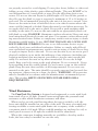
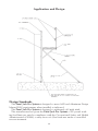
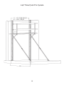
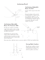
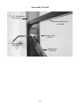
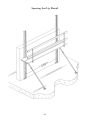
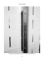
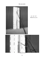
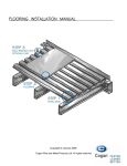
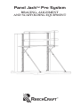
Panel JackTM Pro System
BRACING, ALIGNMENT
AND SCAFFOLDING EQUIPMENT
TABLE OF CONTENTS
Product Overview
3
Performance and Specific Requirements
3
Relevant Codes and Standards
3
Component Description
4
Preliminary Considerations of Use
5
Practical Use
5
Handling and Maintenance
6
Set-Up and Use Instructions Overview
6
Application and Design
8
96” Panel Jack ProSystem
9
144” Panel Jack ProSystem
10
Anchoring Detail
11
Assembly Detail
12
Spacing Set-Up Detail
13
Accessories
14,15
2
Product Overview
Panel Jack Pro System is a product designed for use in insulating concrete
form (ICF) wall forming applications.
The system provides support for builders at the required heights necessary to
construct and fill the ICF form cavity with concrete. It also braces the wall
unit until it has cured and provides the means to plumb and align the wall
before the concrete sets.
Utilizing the Panel Jack Pro System allows the contractor the means to build
ICF walls fast and straight, while ensuring a safe work environment and providing a professional job site appearance.
Performance and Specific Requirements
The Panel Jack Pro System is designed for use within an excavation or at
grade level to support people in winds up to 40 mph. Any other use is not recommended and is at the users own risk.
Requirements identified in this manual represent the minimum requirements,
the user is responsible to research and give precedence to federal, state and
local codes and special site conditions.
Spacing of the bracing product should be determined by the installing contractor in accordance with federal, state and local codes for wind bracing and
scaffold. The maximum spacing for each Panel Jack Pro System product is not
to exceed 7 feet (6’ recommended).
Scaffold planking and handrail materials should be:
American – Number 1 Southern Pine or Douglas Fir.
Approved laminated structural or manufactured planks and stages
are recommended.
Anchoring of components is paramount to the performance of the system,
specific to each site, and is the responsibility of the installing contractor to meet
the following minimum requirements of a safe working load. See engineering
requirements on page 8.
The duty rating for each Panel Jack Pro System is 300 lbs. each or 2 people
per span plus materials including forms and rebar sufficient for three courses.
Relevant Codes and Standards
The user is responsible to review and apply the requirements of federal, state
and local regulations for wind bracing and scaffolding as defined by the above
code agencies. The Panel Jack Pro System is designed to be in compliance
with all applicable OSHA scaffold standards.
This system is also engineered to meet the specific performance demands listed in this manual. All manufacturing processes are subjected to our in house
inspection policy to insure the delivery of quality products void of manufacturing defects.
3
Component Description
Careful consideration has been given to the variety of applications that job
site conditions and wall forming create to develop a product well suited for the
intended use.
The basic system is represented by the following fundamental components:
• Strongback – The main vertical component of the system is a 6005 T-5
extruded aluminum channel intended to be secured to the footing or slab at the
base of the wall and to the wall forms through the provided 1 ½ “ x 3/16” slots
at two points per course. Use #10 screws to fasten the strongback to the ICF
form. Through holes (21/32) drilled 12” on center provide the means for independently mounting the platform bracket and/or the diagonal turnbuckle brace
to the strongback channel through the use of the provided 9/16” x 6” zinc plated HR pin held in position with a clip. The base of the strongback consists of
two removable aluminum clips drilled for anchoring the strongback.
• Diagonal Turnbuckle Brace – The diagonal component of the system has
three fixed adjustment positions to accommodate the 96”, 108”, 120” and 144”
systems. These fixed adjustment positions place the platform bracket between
32” and 48” below the top of the wall. The diagonal turnbuckle brace can be
placed at different angles to accommodate irregular excavation elevations. In
addition, 6” of fine adjustment can be achieved twisting the turnbuckle brace.
Approximately 2” of the threaded portion of the screw should be visible to
ensure equal push and pull of the wall. A swivel foot assembly is mounted at
the base of the diagonal turnbuckle brace and provides 25 square inches of surface area to support the loads. The base plate is equipped with holes sufficient
to anchor the diagonal turnbuckle brace to soil or secure it to the footing, slab
or intermediate floors. There is one 7/8” diameter hole and four ¼” holes per
base plate.
• Platform Bracket – the platform bracket is a fixed position bracket designed
for strength and durability. The platform bracket incorporates a 9/16” diameter
hole to provide secure attachment of the platform bracket to the strongback
through the corresponding holes provided in the strongback. The platform
bracket is designed to accept two 2x10 scaffold planks and a 1-inch toeboard.
Use two #10 x 3” wood screws to secure the overlapping planks together. An
optional vertical handrail support accommodates 2 x 4 top rail, midrails and
toeboards. ¼” holes are provided in the support brackets to secure the
handrails in place. Handrails should be mounted in the inside of the scaffold
work surface.
• Mounting Hardware – All mounting hardware or fasteners supplied with
the system are SAE grade 2 and 9/16” HR zinc plated mild steel.
4
Preliminary Considerations of Use
• Review plans to determine the number of bracing units required for the
project by starting with a bracing unit in the corner.
• Maximum spacing of the brace is 7 feet (6” recommended).
• Do not reduce the number of bracing units relative to the door or window
openings. Instead, use additional bracing units to insure adequate support and
ability to control the wall in areas where voids may occur.
• The bracing unit locations should be centered relative to the overall length of
the wall, but offset relative to the changes in the direction of the wall. For
example, at outside corners the first bracing unit in each direction should be
located as close to the corner as form tie spacing will allow. Bracing on the
inside corners a distance of not less than 27” is required for the clearance of
platform bracket and planking.
• For longer and taller walls, bracing on both sides of the wall is recommended.
NOTE: WOOD BRACING FROM THE GROUND TO THE UNDERSIDE OF THE PLANKING WILL BE REQUIRED AT THE CORNERS
TO SUPPORT PLANKING OVERHANG.
Practical Use
Prepare the layout of the excavation, footings and wall form location in
accordance with the wall designer and ICF installation procedures.
Gather the bracing components within the perimeter of the wall. Ensure that
the diagonal turnbuckle braces are set to the fixed adjustment position relative
to the intended height of the wall and that the fine adjusters are set to allow
equal in and out adjustment of the wall after concrete is placed.
Install a minimum of three courses of ICF forms before erecting the bracing
system.
Locate the positions for the bracing units at the base of the wall and center
them on the form ties.
Stand the strongback in position and secure it to the footing.
Using two #10 pan head wood screws per course of block, secure the strongback to the ICF forms by screwing into the form ties through the slotted holes
in the back of the strongback. The screws should be located at the Top Of The
Slot. Tightened to allow full compression of the form interfaces, but not allowing the form to float upwards.
Fasten the top of the Diagonal turnbuckle brace and platform bracket by
using the 6” pin and keeper pin. Attach the brace and platform bracket assembly to the strongback at the appropriate height location relative to the height of
the wall being formed. Refer to the Panel Jack Pro System drawings in the
back of this user manual. Hold a level held parallel to the strongback at eyelevel and bring the strongback to within 1.5 degrees of plumb with the wall
leaning in towards the perimeter and anchor the base of the diagonal turnbuckle brace. During this process it may be necessary to adjust the angle of the
5
brace relative to the strongback or even to readjust the fixed position to suit
the excavation.
Once all of the strongback and platform bracket and diagonal brace assemblies have been erected, planking can be set in place to continue erection of the
wall.
As each consecutive course is set in place, ensure that a minimum of two
screws per course is used to secure the strongback to the form units.
As the form stacking approaches the intended wall height, the planking can
be moved up to the final position with the planking and handrails in accordance with all applicable codes, and the final course erection and preparations
to pour the walls can be completed.
OSHA requires scaffolding; handrails and toe board if the workers feet are 6’
or more off the ground. Once the erection is complete, do a final check of the
vertical condition of the wall. Ultimately, a slight inward tilt allows for the easiest plumb adjustment after the pour.
Once the wall has been poured, final plumb and alignment adjustments can
be made using the fine adjustment of the individual diagonal turnbuckle braces
in conjunction with alignment and plumbing measures taken during the
process.
Do not remove the bracing or backfill until the wall has reached sufficient
cure in accordance with the wall designer’s direction, and intermediate floor
and/or roof diaphram have been installed.
Handling and Maintenance
With and emphasis toward performance, value and ease of use, the materials
used in the Panel Jack Pro System are the strongest, most lightweight and user
friendly we could design. The painted parts of the product are finished by electrostatic coating to provide excellent durability and corrosion resistance.
Reasonable handling and maintenance will result in years of dependable service. Primary maintenance consists of periodic lubrication of the fine adjustment
threaded portion at the top of the Diagonal Turnbuckle Brace and at the swival
at the bottom of the Diagonal Turnbuckle Brace.
WARNING! FAILURE TO READ AND FOLLOW ALL INSTRUCTIONS MAY RESULT IN SERIOUS INJURY OR DEATH. INSPECTION: Inspect unit for damage before each use. Never use unit if parts are
missing, cracked, bent or after being exposed to any corrosive agent. Label the
unit “Dangerous – Do Not Use” and discard, or call manufacturer. Handle all
units with care. SET-UP AND USE: Do Not Exceed the duty rating of this
unit. The maximum safe weight load for each unit is 300 pounds. Over loading
could cause serious injury or death. Place the unit on a firm surface where footing is solid, rigid and capable of carrying the maximum intended load without
slipping. Do not place the unit on snow, ice, loose gravel, mud, leaves or other
slippery surfaces. Be sure the vertical strongback channel, foot and base clips
6
are properly secured to avoid slipping. Do not place boxes, ladders or other scaffolding on top of the plank to gain additional height. This unit IS NOT to be
used independent of a rated plank or stage. Be sure all locking devices are
secure. Do not use the unit beyond a plank height of 20 feet off the ground or
floor. Be sure the plank or stage is supported a minimum of 12 to 18 inches on
each end. The recommended spacing for the unit is 6 feet not to exceed 7 feet.
Never set the units in front of unlocked doors or in other locations where the
units could be bumped or kicked. Barricades must be used where necessary. Do
not apply side loads to the unit or plank. Never pull or push anything while
working on the units. Do not use the unit without an appropriately rated scaffold plank or stage. DANGER! Aluminum conducts electricity! Keep unit away
from uninsulated electrical circuits and wires. Use extreme caution when working near electrical wires. Failure to comply may result in serious injury or death.
Maximum scaffold height: 21 feet. SECURLY ENGAGE ALL LOCKS AND
BOLTS BEFORE CLIMBING. Be sure to use fall restraint devices as prescribed by local, state and federal authorities. Failure to comply with all local,
state and federal requirements may result in serious injury or death. Never drop
or apply an impact load to the unit. Do not use the unit if you are not in good
physical condition on are under the influence of any substance (including prescription medicine) that may impair your ability to use the unit properly and
safely. Do not leave the unit set up when unattended. Do not use in high
winds. Keep your body center in the work platform. Do not overreach. Never
hoist anything from the scaffold plank. Do not bounce or run on the scaffold
plank. Keep the unit clean and free of all foreign material. Do not store any
material on the unit. The units should be properly supported and secured during transport. Always store in a clean, dry place. WARNING: All accessories
must be installed in accordance with the manufacturers recommended procedure. This product MEETS OR EXCEEDS ESTABLISHED OSHA
REQUIREMENTS.
Wind Resistance
The Panel Jack Pro System is designed and engineered to resist wind loads
form winds of up to 40 mph. Normal construction limits the potential wind
resistance to that which foundation resistance will allow.
When used to provide wind bracing where the strut is staked to soil, the
brace unit shall be installed on two sides of the wall. The mass of normal strip
footings available to resist wind uplift limits safe occupancy of the scaffold to
concurrent winds of 40 mph. Where scaffold members are anchored to soil, at
wind speeds in excess of 40 mph the scaffold should be abandoned.
Where the competent founding materials are available to develop anchor
loads, the brace may be installed on one side only.
7
Application and Design
Design Standards
The Panel Jack Pro System is designed to meet ASD and Aluminum Design
Manual 2000 requirements when installed as indicated.
The Panel Jack Pro System is designed to withstand a 40 mph wind.
The manufacturer has given the Panel Jack Pro System a 300 pound working load limit per unit. In compliance with the Occupational Safety and Health
Administration (OSHA) a safety factor of 4 has been met under a controlled
test environment.
8
96” Panel Jack Pro System
9
144” Panel Jack Pro System
10
Anchoring Detail
Anchoring Adjustable
Brace To Soil
Prepare sill to support strut base
plate.
Except in dense soils, provide
bearing planks to support strut
loads. Planks shall be 2 x 10
(nominal) in cross section and
24” minimum in length supported on mud sills and securely
staked to ground.
Anchoring Adjustable
Brace To Concrete Slab
Provide two anchors at leading
edge. Each anchor to have a safe
working rated resistance of 400#
in pullout and shear.
Scaffold may be used to resist
wind on the scaffold side of the
wall. Provide two anchors at trailing edge when used to resist wind
in two directions.
Base must have sufficient mass to prevent uplift of 1000# and similar loads.
Strong Back Anchor
Provide two anchors at base.
Each anchor to have a safe
working rated resistance of
400# in pullout and shear.
11
Assembly Detail
3” x 4” Aluminum
Strongback
Platform Bracket
4009004
Hairpin Clip
23039
6” Platform Pin
405022
Turnbuckle
4000001
12
Spacing Set-Up Detail
13
Accessories
4003028 Strong Back Extension Coupler with Hardware
14
Accessories
16’, 20’, 24’
Tallwall System
5’ Midspan Brace
15
Corner Pin Assembly
8’, 10’, 12’ Outside or Inside Corner Brace
ReechCraft, Inc.
2001 1st Avenue North
Fargo, North Dakota 58102
1-888-600-6160
[email protected]
www.reechcraft.com