1
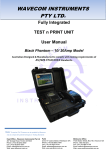
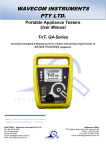
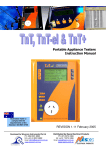
WAVECOM INSTRUMENTS Pty Ltd Portable Appliance Testers User Manual TnT RCD G4-Series Australian Designed & Manufactured to comply with testing requirements of AS/NZS 3760:2010 Standards. Note: TnT Firmware & TnT G4 series in general have the ability to be updated to comply with potential Changes in Testing Standards Head Office - Wavecom Instruments Pty Ltd 257 Grange Road, Findon SA 5023 Phone: (+61) 08 8243 3500 Fax: (+61) 08 8243 3501 Email: [email protected] Web: www.wavecom.com.au Perth Unit 2/17 Casino Street, Welshpool, WA Phone: (+61) 08 9353 1943 Fax: (+61) 08 9353 4319 Email: [email protected] Web: www.wavecom.com.au Melbourne Office 772A Station Street, Box Hill, Victoria 3128 Phone: 1300 793 301 Fax: (+61) 03 9897 4766 Email: [email protected] Web: www.wavecomrentals.com.au Wavecom Instruments Portable Appliance Testers Instruction Manual 2 Wavecom Instruments Portable Appliance Testers Instruction Manual Table of Contents Important Information Accessories Supplied Precautions Manufacturer recommendations Safety Warning TnT RCD Portable Appliance Tester (Diagram) Competent Person Disclaimer Limited warranty 4 4 4 4 5 6 6 6 Technical Information Class 1 (Earthed Appliance) Construction Class 2 (Double Insulated) Construction Testing of Electrical Equipment To Change Test Voltage 7 7 8 8 Integrated Tests Supply mains Test NCNT Test 9 9 First Test Visual Inspection test 10 TnT RCD – Series (Menu A) TnT RCD Test Function Flow Chart Class 1 – Earthed Appliance test – F1 Class 2 – Test Double Insulation test - F2 Lead Test (Ext lead Test) – F3 11 11 12 13 TnT RCD – Series (Leakage Test – Menu B) Test Function Flow Chart Leakage/Run Test Leakage Test Time Kill Switch 13 14 15 16 TnT RCD Test TnT RCD Test Diagram 1 TnT RCD Test Diagram 2 Trip Time Testing Changing RCD Type RCD Trip Current 17 18 19 20 21 TnT RCD Options Menu Introduction Optional Accessories Specifications 22 23 24 TnT RCD Features Meter Mode Meter Mode features 25 26 3 Wavecom Instruments Portable Appliance Testers Instruction Manual Important Information Accessories Supplied Portable Appliance Tester Instruction Manual st Manufacturer’s 1 Calibration Certificate – (Valid for 12 months) IEC test lead (500mm orange/red) Earth Lead with Alligator Clip (1800mm black) Soft Carry Case Locking IEC Power Cable (1800mm Blue) Precautions Unique Locking Power Cable: Please make sure yellow lever is pressed prior to removal of the locking power supply cable. Though the case of the G4 TnT is manufactured from impact resistant & flame retardant ABS, failure to do so, combined with excessive force may damage the rear panel. This revolutionary locking, removable cable is intended not to dislodge during any portable test procedure. Manufacturer Recommendations Calibration: The manufacturer recommends a routine calibration / verification of this unit to ensure the accuracy of readings on a 12 monthly basis, or as prescribed under any additional local Regulatory requirements. Note: Only Wavecom Instruments or its Authorised Service Agents are permitted to repair and Calibrate this Instrument. Failure to perform unauthorised service or repair may void all warranties and Calibration Status. Safety Warning th This 4 Generation TnT RCD series of products have been designed to meet stringent safety requirements, however no device can completely protect persons from the consequences of incorrect use. The testing of Electrical appliances requires that extra care and caution is taken at all times to ensure personal safety. The Manufacturer also advises that appliance testing should be conducted by a Competent and suitably trained person, as referred to under the current Standard AS3760:2010, as well as any additional legislation or rulings in different states. If in doubt, the manufacturer suggests the user contact their responsible Authority. For maximum safety, always ensure that the following advice is followed: The equipment being tested is in good repair. All user instructions are followed. Double check power supply connections. (note LED status) Always use specified fuses and protection devices. Do not use leads that require repair or are damaged. If you are unsure, call a licensed Engineer/Electrician. 4 * See P.5 AS/NZ 3760:2010 def. Wavecom Instruments Portable Appliance Testers Instruction Manual TnT RCD Portable Appliance Tester Instrument description Front Panel View 1. Carry Handle/Body 2 2. LCD Display Screen 1 3 3. Function Key F1 4 4. Function Key F2 5 6 5. Function Key F3 6. Return/Enter Key (Menu/Select) 7 7. Supply Status/Warning indicators 8 8. Main Appliance Test Socket 9. IEC Test Socket for Earth and Extension lead testing 9 View from Back Panel (10A) 2 1 0 Instrument Description 1. 2. IEC Blue Power Inlet (Lockable) incorporates Fuse Holder 10A rated Carry Handle 5 Wavecom Instruments Portable Appliance Testers Instruction Manual Competent Person To ensure that all electrical equipment or devices are inspected, tested and tagged correctly, regulations require that a ‘competent person’ such as a Licensed Electrician be employed to perform the required tests. Please refer to the above definition as described in the current AS/NZ-3760:2010 Standard and in addition, to any other local legislation or jurisdictions as may be relevant in your State. EXAMPLE: A person competent to undertake Inspection and Testing of electrical equipment must have: Knowledge and practical experience of electricity and its hazards. A clear understanding of precautions to avoid danger. The ability to recognise at all times whether or not it is safe for work to continue. The ability to carry out visual examinations of electrical equipment. The ability to distinguish between electrical equipment that is double insulated and equipment that is earthed as well as being able to identify the appropriate test for each type. The competency to safely carry out the Earthing Continuity, Insulation Resistance or Leakage Test and RCD tests on electrical equipment. The knowledge of how to use the relevant testing instruments, interpret and record the results for compliance with the Standard/Workplace requirements. The knowledge to be able to correctly recommend the frequency of testing required. Due to the potential hazards of electrical testing, due care must be taken at all times. Disclaimer Limited Warranty The Manufacturer warrants its products against defects in materials and workmanship for a period of 12 months from the date of purchase. During the warranty period, the manufacturer will repair (or at its option replace at no charge) the product that proves to be defective. This warranty does not apply if the product has been damaged by accident, abuse, misuse or as a result of service or modification by anyone other than manufacturer of the TnT RCD. The TnT RCD product range of devices or its manufacturer IS NOT RESPONSIBLE FOR INCIDENTAL OR CONSEQUENTIAL DAMAGES RESULTING FROM THE BREACH OF ANY EXPRESS OR IMPLIED WARRANTY, INCLUDING DAMAGE TO PROPERTY AND TO THE EXTENT PERMITTED BY LAW, and DAMAGES FOR PERSONAL INJURY. The Distributors of this product cannot assume liability or responsibility for any loss or damage resulting from the use of this device. The TnT RCD manufacturer reserves the right to discontinue models, change specification, price or design, at any time without notice or obligation. 6 Wavecom Instruments Portable Appliance Testers Instruction Manual Technical Information Class 1 (Earthed Appliance) Definition (Single basic insulated and protectively earth equipment) This type of product design provides two safety barriers between all live conductors at dangerous voltages and the equipment user. The provision of basic insulation between exposed metal parts and live parts is the first barrier to provide basic protection against electric shock. The second safety barrier is by the connection of exposed (accessible) conductive (metal) parts to the protective earthing conductor (earth wire) in the fixed wiring of the device/Installation. The protective earthing terminal of the equipment must be marked with the word "earth" or the symbol "E" or the symbol for Earth Terminal or Protective. To perform this test a continuous earth loop must be made between the exposed conductive material (metal) and the TnT RCD appliance tester. This is done by means of connecting the earth lead with the crocodile clip/probe attached to a GOOD earth point (paint & coatings will not provide effective connections) and the DUT (Device Under Test) plugged into the TnT RCD appliance testers’ DUT socket. The Maximum allowable limit is less than1.0 (ohm). Class 2 (Double Insulated) Definition (Double insulated equipment) This method of construction employs two safety barriers comprising two layers of insulation between dangerous voltages and the user of the equipment. The first layer of insulation is formed around the live conductor and is termed ‘the Functional Insulation’. The second layer of insulation is termed ‘the Supplementary Insulation’. In Class II equipment, protection against electric shock does not rely on basic insulation only, but has additional supplementary insulation such as double insulation or reinforced insulation provided, there being no reliance on precautions in the fixed wiring of installation. Class II equipment is marked with the words "DOUBLE INSULATION" or the symbol For double insulated under Safety Symbols: Note 1 – Double Insulation is insulation comprising both basic and supplementary insulation. Note 2 – Reinforced Insulation is a single insulation system with a degree of protection against electric shock, which is equivalent to double insulation. 7 Wavecom Instruments Portable Appliance Testers Instruction Manual Testing of Electrical Equipment Many testing personnel have some reservations in testing sensitive, electronic equipment using a 500V DC insulation test. There is a perceived fear of causing internal damage from over voltage. With the introduction on the TnT RCD Range of appliance testers, these concerns are alleviated. The TnT RCD Range of electrical portable appliance testers is safe to test electronic equipment as the tests are carried from Active-Neutral (shorted by a relay inside the tester) to Earth. No dangerous voltages pass through in this mode to the internal components of the DUT (Device Under Test). If these tests are done using an Insulation Tester only and the user tests Active to Neutral, this would be a cause of potential damage, this is why the TnT RCD product range is far safer to use. Some changes may be required in certain configurations where fitted surge protection devices (MOV's) in the DUT may cause a failed test result. Applying 500V in this these situations can cause the surge protection devices to trip, therefore conducting the applied voltage to earth, thus showing a failure of insulation. In these instances the test voltage should be changed to 250V then retest. If DUT still fails, check with the DUT Operators Manual or an electrician. [for details see - ‘Double Insulation Test’ 250/500VDC to change test voltage]. Under these circumstances, it would be difficult for any damage to occur to either the surge protection device or the DUT, as there is insufficient current generated by the TnT-el appliance tester. Leakage Test: If there are any doubts with insulation testing of the equipment, the standard (AS/NZ3760) allows for an alternative test method. A Leakage Test can be performed instead. (The TnT RCD – Series are designed to perform these tests). NOTE: 10Amps MAXIMUM Resistive Load only (Standard TNT RCD - Series units). A Leakage Test applies power to the Device Under Test (DUT) and measures the imbalance of leakage current from the DUT between the active and neutral conductors. The leakage is tested to the limits specified in the standard and a Pass/Fail result as well as a digital reading is provided to ensure that the user gains as much information as necessary. Earth Continuity Test: The TnT-RCD conducts earth continuity tests at Approx. 200mA. Continuity tests at higher currents are not required and are not recommended on certain equipment as this can cause severe damage or premature failure to the DUT under test (as per AS/NZ3760). 3 Phase Testing: * (Note Optional Adaptor is Required) 3 Phase appliances can be tested by the TnT RCD series appliance testers. This test is carried out by using the adaptor connection socket. As the insulation tests are from Phase to Earth, only a 500V insulation test is required. These adaptors can be made by your electrician or purchased as an accessory. [See ‘Optional Accessories’ for details - when ordering please state plug configuration of 3 phase plug.] Please note: (The TnT RCD cannot perform 3 Phase Leakage test. Contact Wavecom Instruments Pty Ltd for the appropriate tester). To Change Test Voltage To change the test voltages select the "change ins" from the options menu. Please refer to the (Special Functions) section of this manual. Please Note: The TnT RCD - Series will automatically default to 500VDC when restarted. 8 Wavecom Instruments Portable Appliance Testers Instruction Manual Integrated Tests Supply Mains Test The Supply Mains Test checks the polarity and connectivity of the mains supply by LED's. This test is also a part of all the testing functions of this unit. If the N-E (red) light is on and you need to conduct load/leakage tests DO NOT CONTINUE. If you are carrying out standard Insulation and Earth Bond tests, it is generally safe to continue. This light will glow if a voltage difference lies between the neutral and the earth, or if no earth is connected to the TnT- Series supply. (If working with a generator or inverter, this is most likely to occur and you may need to consult an electrician before proceeding). If both the A-E & A-N (green) lights are on but not the N-E (red), mains supply test is ok, continue to test. If both of the N-E (red) & A-E (green) lights are on, consult an Electrician, as there is a fault with the Mains Supply. NCNT Test (No Connection No Test) The TnT RCD – Series appliance testers ensure that the appliance is plugged in and switched on. This test is also a part of all of the testing functions of this unit. This test function ensures that the appliance is plugged into the TnT RCD appliance tester and that it is switched on. If the device is not plugged in and the TnT RCD appliance tester detects that no device is present, plug in to continue the test or confirm ‘QUIT’ to return to the main menu. If for some reason the NCNT circuit does not detect the device but it is actually plugged in and turned on, the operator will need to override the NCNT function. To do this Over Ride Press F3 (Done with user discretion) With an emphasis in the Standard AS/NZ3760 for carrying out the live testing the TnT RCD - Series appliance testers will indicate for you to check if the device is plugged in and switched on. If the device is not plugged in and/or recognised, it may require a live test therefore making it necessary for the operator to carry out a full functional Leakage Test (Available on all models of TnT RCD – Series). This function is to ensure that correct testing procedures are carried out in accordance with the Standard AS/NZ3760. *Optional Note: When using 3-Phase adaptors the NCNT function will need to be over ridden by pressing the ‘OK’ key prior to the TnT appliance tester performing the assigned test. Some single Phase appliances controlled by contactors will also require manual over ride. In some instances holding the ‘ON’ button will enable the NCNT function to work normally. 9 Wavecom Instruments Portable Appliance Testers Instruction Manual Visual Inspection (First Test) VISUAL INSPECTION IS TO OCCUR BEFORE ANY OTHER TEST IS CARRIED OUT BEFORE USING ANY OF THE RANGE OF TnT RCD APPLIANCE TESTERS (Theory has it that up to 90% of errors are detected just by doing a thorough complete visual inspection, this will also determine what specific type of test will be conducted on the inspected appliance.) Take your time and read information carefully, compliance plates or stickers attached to the appliances being inspected, have valuable information like volts, amps, power and symbols like the earth symbol and the double insulated symbol that will help you identify what test needs to be conducted with that appliance. (Explained in detail refer pg. There is no damage or component defects to the accessories, plugs, outlet sockets or connectors (physical). There are no cracks &/or abrasions. There are no exposed inner cores or conductors (flexible) and the supply cords are not twisted or distorted. Any Fuse / Over load protection components (if fitted) are checked. All labels, markings and warning indicators (of the maximum load to be connected to the device) are legible and intact. The insulation is not damaged in any way i.e. melted, cuts or abrasions. There are no iron filings in the insulation. There is no insulation tape on the lead. Any flexible cords and/or leads are effectively anchored (glands and grommets intact). All covers or guards are in place and secure as intended by the supplier/manufacturer. All safety devices and systems are in good working order. (i.e. overload latches & buttons). No dust &/or dirt obstructs any exhausts or ventilation outlets. All controls are working properly and are secure and aligned. Important: If result is a FAIL!! If any Equipment FAILS ANY of the above, it should be deemed to have FAILED the Visual Test, and therefore no other tests need be performed. If this is the case the Equipment should be tagged with a DANGER TAG and removed from service. It is recommended by the manufacturer and distributor of this product that it SHOULD NOT BE RETURNED TO SERVICE. To do so would be considered unsafe. The Wavecom series of appliance testers have been designed & manufactured to exceed and comply with the AS/NZ:3760 standard, and to aid the end user with simple everyday electrical symbols that they can identify with which will allow them to start the testing regime quickly and efficiently, without any complexity as illustrated below. 10 Wavecom Instruments Portable Appliance Testers Instruction Manual TNT RCD – Testing (Menu A) TEST Function Flow Chart Main Menu A Class 1 Earth Bond or Continuity Test Class 2 500V Double Insulation Test Extension Lead Test Class 1 - Earthed Appliance Test - F1 Please Note: A Visual Inspection test must be carried out before any others (refer to First Test Section) The Class 1- Earth Appliance Test completes the following sequences as part of its procedure: 1. Integrated Supply Mains Test Refer to Integrated Test section 2. Integrated NCNT Test Refer to Integrated Test section 3. Earth Bond Test (@ 200mA): 200mA test current, pass level less than 1Ω 4. Insulation Test (@ 250V or 500V): pass level greater than 1MΩ Please Note: 250V insulation testing applies to Class 1 appliances if selected (refer to Technical Information for details to change test voltage) In some situations if the DUT is labelled with “Surge Protection Fitted” or if it contains MOV’s (Metal Oxide Varistors), conduct a 250V-insulation test. *If unsure refer to the AS3760 Standard. Should it still fail, remove it from service. (Refer to the Technical Information section to change test voltage). 11 Wavecom Instruments Portable Appliance Testers Instruction Manual Procedure: 1. 2. 3. 4. 5. 6. Complete a Visual Inspection. Only proceed if test passed. Plug device into appliance socket. Connect earth clip to any exposed metal on the device. Press the F1 key and wait for results (ensure that device is powered on) Read and record results appropriately Unplug device 7. Tester will return to Main menu A automatically If the result was a pass - Tag with PASS tag showing "next test due" date and return the device to service. If the result was a fail - Tag the DUT with a DANGER tag and remove the device from service. Please Note: Ensure that the device is isolated from any ground loop. Class 2 Test - Double Insulation Test - F2 Please Note: A Visual Inspection test must be carried out before any others (refer to First Test Section) The Double Insulation Test completes the following test sequences as part of its procedure 1. Integrated Supply Mains Test Refer to Integrated Test section 2. Integrated NCNT Test Refer to Integrated Test section 3. Double Insulation Test (@250V or 500V): pass level greater than 1MΩ Procedure: 1. Complete a Visual Inspection (Note: Only proceed if test passed) 2. Plug the appliance into appliance test socket. 3. Connect earth clip to any exposed metal on the device (if any, or device can be wrapped in foil or use metal mesh braid, Part No: WCM-ES 500) 4. Press the F2 key and wait for results (ensure the device is powered on) 5. Read and record results appropriately 6. Unplug device 7. Tester will return to Main menu A automatically If the result was a pass - Tag with PASS tag showing "next test due" date and return the device to service. If the result was a fail - Tag with a DANGER tag and remove the device from service. In some situations if the device is labelled with “Surge Protection Fitted” or if it contains MOV’s (Metal Oxide Varistors), conduct a 250V-insulation test. (Hint always read the compliance plates during Visual Mainly on surge protected powerboards) *If unsure always refer to the AS3760:2010 Standard. Should it still fail, remove it from service. (Refer to the Technical Information section to change test voltage). 12 Wavecom Instruments Portable Appliance Testers Instruction Manual Lead Test (Ext Lead Test) - F3 Please Note: A Visual Inspection test must be carried out before any others (refer to First Test Section) The Lead TEST completes the following sequence as part of its comprehensive testing procedure: 1. Integrated Supply Mains Test Refer to Integrated Test section 2. Earth Bond Test (@ 200mA): 200mA test current, pass level less than 1Ω 3. Insulation Test (@ 250V or 500V): pass level greater than 1MΩ 4. Continuity and Polarity Test 240VAC @ 2mA Checks continuity & polarity of leads Procedure: 1. 2. 3. 4. 5. 6. Complete a Visual Inspection. Only proceed if test passed. Plug in supplied orange IEC adaptor lead supplied into front IEC socket. Plug male end of extension lead or power board in to TnT RCD – Series appliance socket. Press the F3 key and wait for results. Read and record results appropriately. Unplug extension lead/power board. 7. Tester will return to Main menu A automatically. If the result was a pass - Tag with PASS tag showing "next test due" date and return the device to service. If the result was a fail - Tag with a DANGER tag and remove the device from service. Please Note: Extension leads should always be uncoiled before using or testing. Please ensure that the IEC Adaptor & the IEC socket are inserted firmly or it may result in a continuity/polarity fail. TnT RCD Main Menu B- Leakage Test Function Flow Chart Main Menu B For RCD trip time or ramp test refer to page 17 Class 1 Leakage Class 2 Leakage RCD Leakage 13 Sub Menu Wavecom Instruments Portable Appliance Testers Instruction Manual Leakage / Run Test The Leakage Test is an alternate method to perform insulation resistance tests. Leakage testing is a major function of the TNT RCD - Series Please Note: A Visual Inspection test must be carried out before any others (refer to First Test Section) This test determines errors of leakage not otherwise detected in a normal insulation test. If there are any doubts with insulation testing of the equipment, the Standard (AS/NZS 3760 since 2001) allows for a leakage test to be carried out instead. The TNT RCD - Series appliance testers have been designed to perform these tests. The Leakage Test applies power to the Device Under Test and measures any imbalance or leakage current. The leakage is tested to the limits of the class types specified in the Standard AS/NZS 3760 i.e. Class 1 = > 5mA as Fail. The Limit of imbalance measured on the TnT-RCD, appliance tester will read well in excess of the limits set in mA. However, should the supply circuit be protected by an RCD this device will trip anywhere between 10 to 30mA and trip the mains supply switch OFF. Procedure: 1. Complete a Visual Inspection. For details refer to the First Test section. If the device passed the Visual Inspection, continue with the following instructions, if not, refer to the First Test section. 2. Press the return key to view Main menu B. 3. Press a function key (as follows) to start the test/s. Press either F1, F2 or F3 depending on the type of device you are testing). F1 = Earth Leakage, limit set to MAX then 5mA fail. F2 = D/insulated leakage and ext. leads, limit set to MAX then 5mA fail. F3 = RCD leakage. CONFIRM IF SAFE TO CONTINUE? OK/QUIT. IF OK, DEVICE WILL POWER SWITCH ON. ENSURE ITEM AND ENVIRONMENT FOR SAFE OPERATION! 4. Results are displayed, read and record appropriately. 5. Unplug DUT. 6. Press Enter until you return to the main menu. If the result was a pass - Tag with the appropriate tag including "next test due" date and "return to service". If the result was a fail - Tag with a DANGER TAG and remove from service. The Leakage Test allows the user to operate the appliance in normal operation conditions and measure its Operating Leakage current. The displayed parameter is mA. The mA Display Range 0.0 to 22.0 mA. A predefined value for individual class types is programmed into your TNT RCD - Series appliance testers. These limits are set according to the AS/NZ3760. Should these values change in future it can be simply altered in firmware. A Pass / Fail will also be displayed at the end of the test. The run time period can be adjusted (by 5sec increments). The value can be changed by selecting the leakage test time in the options menu. See the special functions section of the manual for more details. The factory default setting is 20sec. The value for the leakage runtime is also used for the power test (plus models only). Caution: Before operating ensure the equipment is firmly secured to eliminate the possibility of causing injury or damage. This function will power the Unit on, Please make sure the drills or any blades of any rotating devices have been removed prior to any testing and have clearance from body or object. Appliances may jump off benches and may need to be secured by clamping them, or they may cause serious damage if not secured properly. 14 Wavecom Instruments Portable Appliance Testers Instruction Manual Leakage Test Time The leakage test time is adjustable. You may need to adjust timing in this feature if the DUT has a long power up time or requires special power on procedure. Default time for Leakage Test is 20 seconds. From this menu you can change the test time from 5 seconds to 28800 seconds. Adjusting to any less than 5 seconds will put the test time to infinite. Press the key to increase the test time. Press the key to decrease the time. Press the key to set the new leakage / power test time. Press the key to escape out of the menu. No changes saved. Audio Option - All Enabling the audio option will make the TnT RCD use a sound to indicate a pass or a fail at the end of a test. If the TnT RCD unit has never been altered then the audio beep is disabled. Press the key to disable. Press the key to enable. Result hold time Press Enter and F2 to enable options then F2 until you get to result hold time this allows you to change the time that the results values are showed on the TnT RCD display screen Press the key to increase time. Press the key to decrease time. 15 Wavecom Instruments Portable Appliance Testers Instruction Manual KILL SWITCH To stop operation press the return/enter key at any time. The unit will power down after 20 seconds as factory default Caution: This test turns the Equipment ON. The power / leakage test can handle up to 10 Amp (Resistive) Load MAX. Exceeding this value will blow the external M205 ceramic fuse. Care should be taken when testing inductive loads (i.e. AC motors) with large start up currents. If 10A HBC fuse is blown the appliance will not operate in Leakage test modes. Replace fuse only with M20 10A HBC fuses. Any other fuse voids warranty and manufacturers design. Caution: DO NOT OPEN TnT RCD - Series case as there are no serviceable parts inside and you can void your Warranty 16 Wavecom Instruments Portable Appliance Testers Instruction Manual TnT RCD Test - Time Test / Ramp Test Main menu B Please Note: Where ANY TnT RCD testing, is to be carried out any circuit that is protected by an RCD in the main switchboard (upstream), it’s most likely to trip this upstream RCD. When performing RCD trip time or Ramp current tests on any (portable) RCD devices, the RCD in the switchboard may trip faster. This is due to increased upstream levels of leakage current from the additional circuits and devices connected to it. The fixed RCD’s can also have better connectivity, sensitivity and mechanical mechanisms. To avoid tripping large areas in the work place monitored by the switchboard RCD it is suggested that an RCD (Isolation Transformer) be used. These are designed specifically for the purposes of field RCD tripping. DO NOT use these Transformers for any other purpose. Ratings 240VAC in 240VAC Out @ 30VA Fuse protected Primary winding 500mA To perform RCD tests the TnT RCD supply lead needs to be plugged in to the RCD device to be trip tested. For tripping switchboard mounted (Fixed) RCDs Plug TnT RCD into GPO marked RCD protected or if known to be protected circuit. (Diagram 2) (Isolation Transformer Required) If testing portable RCD devices on power boards or extension leads plug TnT RCD into power board or lead (Isolation Transformer Required) Diagram 1 For Testing Portable RCD TnT RCD Power Lead Wall GPO Power Outlet TnT RCD Portable RCD 17 Wavecom Instruments Portable Appliance Testers Instruction Manual RCD Test - Main menu B Diagram 2 For Testing Fixed RCD TnT RCD Power Lead TnT RCD Wall GPO Main Switchboard with RCD To do this test select the second menu, press and release the Return/Enter button. This menu will now display 2 functions: Leakage Test RCD Test To enter the RCD menu press and release the F3 button. Press F1 to select the time test. Trip Time Testing: This principal is designed to trip RCD devices at a fixed current and to determine the trip time of the RCD device. This function is factory set to 30mA for fast testing the user can set the current to X0.5, X1.0, X 5 using the RCD Multiplier. I.E. (30mA X 0.5 =15mA) (30mA X 1.0 = 30mA max) 500mA output.) (this also is effective on any set test current of the RCD tester from 5mA to 30mA X 5.0 = 150mA 18 Wavecom Instruments Portable Appliance Testers Instruction Manual These tests should result in no-trip, trip & fast trip times respectively. F1 - 0 degree This is the positive half of the mains supply cycle. (50HZ Aust/NZ). Press F1 – The preset mA test current will then be used in the following test and begin the trip test from the positive half of the sine wave. F2 - 180 degree This is the negative half of the mains cycle, (50HZ Aus/NZ). Press F2 - The preset mA test will then be used in the following test and begin the trip test in the negative half of the sine wave. Performing a Time Test: The displayed trip time is in milliseconds. This is the time taken for the RCD device to trip once the injected fault current has been applied. The TnT RCD injects a true fault current value using a real time compensation calculation of the actual voltage at the time of test hence delivering a true and accurate trip current. RCD Test Options: F3 – Change to select tested: This allows the user to set the trip current level, 5mA to 500mA. The RCD type can also be select here depending whether the unit is a type I or type II. See the next section for explanation. From the options menu press F2 to change the current level and F3 to change the RCD type. Adjusting the current level: The TnT RCD displays and maintains the last, set trip current value. If the user wishes to change the value of the trip current the following steps enable the changes Press and release F2 from the options section to display test current. 19 Wavecom Instruments Portable Appliance Testers Instruction Manual Up - This button raises the trip current in 1mA increments to 500mA. Hold the button and the value will scroll faster the longer it is pressed. Once 500mA limit is reached the value will then loop over and start again from 0mA Down - This button decreases the trip current in 5mA increments. Hold the button and the value will scroll faster the longer it is pressed. Once 0mA limit is reached the value will then loop over and start again from 500mA. Set - This button sets the selected current for the next trip time test. The TnT RCD will then return to the current trip time test screen. Changing RCD Type: Depending on the RCD, the RCD type needs to be selected from the options menu. These options change the pass / fail values when performing RCD tests. Please make sure that you have the correct RCD type selected. The RCD types are: Type I: Has a trip time of < 40mS and a trip current of < 10mA. These types of RCD's are mainly used on sites containing medical equipment. These types of RCD's must be compliant with AS3551. (please refer to this AS3551 standard if unsure) Type II: Has a trip time of < 300mS and a trip current of < 30mA. Unless specified on the RCD device nearly all RCD will be this type. This is the default setting on all new units. Selects type I and saves to memory Selects type II and saves to memory RCD Timed Test (continued): Press the F1 key to select the 0 degree test and the F2 key to select the 180 degree test. Use the F1/F2 keys to scroll through the multipliers X0.5 X1.0 X5.0 of the set current. Maximum output current = 500mA. I.E if set test current were 100mA then 100 X 5.0 =500mA. If set test current = 200mA then maximum output 5 x 200mA =1A is out of range. Unit will not deliver this output current and display on Screen “OUT of RANGE”. Press F3 to start test. TnT RCD will display results for 5 seconds after mains supply is tripped. If the power is not reset by the time the unit loses power then the result will be displayed on power on. Caution: Pressing F3 at this point will cause tripping if RCD fitted to circuit RAMP CURRENT TEST. This testing principal is designed to trip RCD devices using a ramping up current value, to determine the trip current of the RCD device. This useful test allows the user to determine circuit leakage load/pre-loading of RCD circuit. This can assist in determining nuisance tripping issues (RCD is too sensitive) or determining RCD performance if suspected faulty or inconsistent in performance. The TnT RCD has a nominal leakage current of 2mA, which should be added to the result of test. E,G. if RCD tripped at 22mA + 2mA(TnT RCD)=24mA trip current. 20 Wavecom Instruments Portable Appliance Testers Instruction Manual RCD Trip Current. Press F2 to show the Trip current screen. Caution: Pressing F3 at the RCD ramp test screen will cause tripping if RCD fitted to circuit. F2 can be pressed to change the RCD type at this point. See "Changing the RCD type" for details. The Trip Current Test will ramp the mA current up until the RCD breaker trips. Current range 2.55 - 500mA. This test can go for up to 10 sec to scroll through full range if RCD faulty or not fitted. Repeated testing in this mode will cause heating of TnT RCD. Should over heating occur the internal temperature sensor will cause display to indicate “over temp allow to cool” This requires the TnT RCD device to be best left unplugged for several minutes allowing unit to cool. TnT RCD will display results for 5 seconds after mains supply is tripped. If the power is not reset by the time the unit loses power then the result will be displayed on power on. 21 Wavecom Instruments Portable Appliance Testers Instruction Manual TNT RCD Options Menu Introduction Here you can adjust the way the TnT RCD behaves under certain tests and other test functions. Some options are not available to some models. (Depends on firmware version) To Access TnT RCD Options Menu: . From either the Enter barcode screen or the main menu A screen hold down the return button. With this button held down press the F2 key you should now be in the TnT options screen. The screen displays 1 option at a time. You can select this option by pressing the return button. To select the next item press the F2 button. Pressing the F3 button escapes out of the TnT options menu. Change Insulation Voltage Some DUT contain MOV's (metal oxide varistor) or commonly known as spike protection devices. These limit the mains voltage to about 280VAC. If you attempt to perform a 500VDC insulation test on one of these devices you will get a failed result. To fix this problem select the 250V option. Press the key to select the 250V option. Press the key to select 500V option. You can also set the unit back to 500V by switching the mains power off and on again. The default insulation voltage is 500V. 22 Wavecom Instruments Portable Appliance Testers Instruction Manual Optional Accessories WinPATS LogBOOK Part No: WCM-WinPATS LogBOOK WinPATS LogBOOK PRINT Part No: WCM-WinPATS Log PRINT (Used with Wavecom Printer) Barcode Scanner Part No: WCM-1200 Scanner USB (With LogBOOK only) 500mm Earth Strap Part No: TnT-ES 500 WAVECOM Tag Printer Part No: WCM-Wavecom Printer (with LogBOOK only) 3-Phase Adaptor 20A Part No: WCM-3Phase-20A 3-Phase Adaptor 32A Part No: WCM-3Phase-32A 3-Phase Adaptor Multi (20A) (32A) Part No: WCM-3Phase-M HBC Fuse Part No: WCM-HBC10AM205 Test Probe Kit Part No: WCM-Probe-Kit Rugged Case (L) Part No: WCM-HTC-L Tag Remover Part No: WCM-Kutter Laminated Tags Part No: WCM-TT-Generic-Tags 23 Wavecom Instruments Portable Appliance Testers Instruction Manual SPECIFICATIONS TnT RCD ®G4- Series Mains Supply Test Checks Polarity and continuity of mains supply by LED indicators (A-N, A-E, and N-E). (Flashing-Test Fail indicator) CLASS 1 Earthed Appliance Appliance Check: Ensures appliance is plugged in and turned on. Earth Bond Test: 200mA test current. Pass level Less than 1.0 Ω. Measurement: 0.01Ω to 10 Ω. Insulation Test: 500VDC / 250VDC. Pass level Greater than 1M Ω. Measurement: 0.1Ω to 10MΩ. *See also Leakage Test CLASS 2 Double Insulated Appliance Appliance Check: Ensures appliance is plugged in and turned on. Earth Bond Test: 200mA test current. Pass level Less than 1.0Ω. Measurement: 0.1Ω to 10Ω. Insulation Test: 500VDC / 250VDC. Pass level greater than 1MΩ. Measurement: 0.1Ω to 10MΩ. *See also Leakage Test Extension Leads Earth Bond Test: 200mA test current. Pass level Less than 1Ω. Measurement: 0.01Ω to 10.0Ωs Insulation Test: 500VDC / 250VDC . Pass level Greater than 1MΩ. Measurement: 0.1Ω to 10.0MΩ. Continuity Test: 250VAC check continuity and polarity of leads. Displays Pass/Fail. Polarity Test: 250VAC check continuity and polarity of leads. Displays Pass/Fail. Leakage Test * Leakage Current: 0 to 30.0mA at 200 to 265V Earth Leakage Test: 240VAC Mains. Pass level 1, 2.5, 5.0 mA leakage test levels with up to 10Amp load operation. Note 1: Pass level for CLASS 1 is 5 mA Pass level for CLASS 2 is 1 mA Note 2: Leakage test may be performed if for any reason a standard CLASS 1 or CLASS 2 is not possible. RCD Test Trip current: 2 to 500mA in 1MA steps. User selectable. Trip time: 0 to 3,000ms at .001sec resolution. Current ramp Trip Test: 0 to 500mA in 1MA increments. Meter Mode® Load Current: 0.0 to 10Amp Voltage: 200 to 265VAC Apparent Power: 0 to 2400VA Power: 0 to 2400W 24 Wavecom Instruments Portable Appliance Testers Instruction Manual TnT RCD ®G4- Series Features Meter Mode ® - (Independent of all other Tests) Meter Mode Screen How to Activate Meter Mode Hold F3 from main screen display for 2 seconds Main Menu A Screen will change to show volts by default when socket is ( not powered ) Plug appliance into testers , test socket , Press F3 to go into power mode and will show (Warning device will be powered) Press F3 again to continue and (power the device). If you continue the A-N LED on the tester will flash green and device will power up. Otherwise press enter to exit. Warning Screen Volts Screen Amps Screen Watts Screen Volts/Amps Screen Press the enter key to stop the power mode and return to volts. Pressing F3 key will start power mode again. TnT stays in Meter Mode regardless of power on/off until you exit Pressing Return key will exit meter mode and return the main menu. If the TnT RCD is reset in meter mode it will return to meter mode when powered up again. Meter Mode Uses Meter Mode is a new and versatile function of the new Gen 4 tester that will allow you to display Electrical Parameters from a Power outlet source or from the appliance under test. Typical Applications Example.: Measuring the Power of a bar heater, or electric power drill check the ratings and compare them to that on the compliance plate etc. Quick test of Power outlet Voltages in rooms or locations split from multiple circuits. 25 Wavecom Instruments Portable Appliance Testers Instruction Manual Meter Mode Features – (Four Discrete Options) Electrical parameters are displayed as Volts, Amps, Watts, and Volt / Amps These electrical parameters will be displayed on the Testers main screen display. Select from the 4 Test available in Meter Mode. Meter Mode Measures and displays volts in AC, Current in Amps, Power Measurement in Watts and VA in Volt/AMPS Explanation of Electrical Parameters Volts A volt is the unit used to measure the energy available in the electrical current of a circuit. Voltage controls the available electrical power (wattage). Amperes An amp is the unit used to measure electrical current as it flows past a specified point. Watts A watt is the unit used to measure the amount of actual flowing electrical energy. Volt-Amps A volt-amp is the unit used to measure the apparent electrical power used by computing equipment. Mathematically, it is expressed as volts times amps (V*A). *Meter Mode ® is a unique function of all TnT RCD Gen 4 Models. Uses of Volt-Amp Measurement Because it represents the amount of energy computing systems may draw from a power grid, the VA is used to determine the kind of wiring and circuit breakers required to support the computing equipment in question. Watts and VA (Detailed Explanation) The power drawn by equipment is expressed in Watts or Volt-Amps (VA). The power in Watts is the real power drawn by the equipment. Volt-Amps are called the "apparent power" and are the product of the voltage applied to the equipment times the current drawn by the equipment. Both Watt and VA ratings have a use and purpose. The Watt rating determines the actual power purchased from the utility company and the heat loading generated by the equipment Safety Precautions Make sure you have a clear and safe area when powering any equipment, remove any drills bits etc before testing any equipment. Always read equipment compliance plates. Disclaimer Meter Mode is to be used for quick simple indicative electrical parameter measurements. Providing reasonably accurate readings without the need to carry any other instruments. It is not intended to replace specific, more accurate individual test equipment, nor is its purpose to replace prescribed testing requirements. It in doubt please consult a qualified electrician when unsure or perform proper test procedures. 26 Wavecom Instruments Portable Appliance Testers Instruction Manual Disclaimer – E&OE All specifications may be subject to be change by Wavecom Pty. Ltd. without prior notice. Updated Specifications & Model changes may be found on the Wavecom website:- www.wavecom.com.au At the time of developing this manual, all care and consideration for accuracy has been implemented. Wavecom accepts no responsibility for any errors or omissions in this document. This is partly based on the fact that Electronics & Electrical testing and specifications worldwide are constantly changing and that Local, State and National Regulatory Authorities may also have differing or additional requirements. It is strongly recommended the Purchaser check Local Regulatory Standards that may be applicable in your region. No part of this document may be Reproduced, Copied, Modified or Utilised in any way or form without the permission of Wavecom Instruments in writing. The TnT RCD G4 series is Designed and Manufactured by: Wavecom Instruments Pty. Ltd. Australia. Head Office: 257 Grange Road, Findon Adelaide, South Australia 5023. www.wavecom.com.au Tel.: +61 (0) 8 8243 3500 Fax.: +61 (0) 8 8243 3501 Email : Enquiries: [email protected] Product : [email protected] Technical: [email protected] 27 Wavecom Instruments Portable Appliance Testers Instruction Manual Portable Appliance Testers TnT® G4-Series www.wavecom.com.au V1742015 Note: TnT Firmware & TnT G4 series in general have the ability to be updated to comply with potential Changes in Testing Standards 28