1
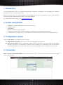
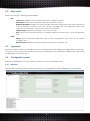
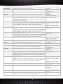
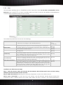
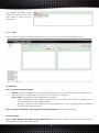
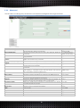
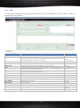
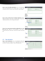
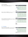
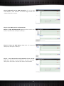
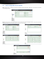
n-Core Configuration Tool 2.x User Manual Rev. 20150211 Configuration Tool 2.x User Manual Table of contents 1. Introduction ....................................................................................................................... 2 2. System requirements ........................................................................................................ 2 3. Configuration options ....................................................................................................... 2 4. Connection ....................................................................................................................... 2 5. Main Components ............................................................................................................ 3 5.1. Tree of nodes ................................................................................................................................................. 3 5.2. Main menu ..................................................................................................................................................... 4 5.3. Log panel ....................................................................................................................................................... 4 5.4. Configuration panel ..................................................................................................................................... 4 5.4.1. Network .................................................................................................................................................. 4 5.4.2. Behaviors ................................................................................................................................................ 6 5.4.3. Rules ........................................................................................................................................................ 9 5.4.4. Locating ............................................................................................................................................... 10 5.4.5. Data ...................................................................................................................................................... 11 5.4.6. Advanced ............................................................................................................................................ 12 5.4.7. OBD ....................................................................................................................................................... 13 5.5. 6. Context menu ............................................................................................................................................. 14 Backup ............................................................................................................................ 15 6.1. Network and locating parameters.......................................................................................................... 15 6.2. Save behaviors ............................................................................................................................................ 16 6.3. Save rules ...................................................................................................................................................... 17 6.4. Save OBD queries and OBD parameter................................................................................................. 18 6.5. Load a configuration from an xml file .................................................................................................... 20 7. Additional information ................................................................................................... 21 1 Configuration Tool 2.x User Manual 1. Introduction n-CoreConfiguration Tool is a software application that allows configuring and managing the different parameters of the n-Core Siriusdevices. Before using this tool, it is recommended to be familiarized with the functionalities of the n-Core platform and the technical characteristics of the n-Core Sirius devices. For further information, please, visit www.nebusens.com 2. System requirements 32/64-bit PC using MS Windows™ XP/Vista/7/8 or Linux. 5MB disk space. 128MB RAM. 800x600 or higher screen resolution. 1 USB host port (incl. USB-to-UART controller), 1 RS-232 port or a LAN/WAN connection. n-Core DLLs and a valid n-Core License File in the execution path of the n-Core Configuration Tool. 3. Configuration options There are two ways to configure the Sirius devices: 1) Via serial port or socket. Each device can be configured independently. 2) Over The Air (OTA). Allows configuring multiple devices wirelessly connected through the ZigBee network. In this case, it is necessary to connect the coordinator or a collecting node of the network to the USB, RS-232 or TCP/IP port. Sirius devices are preconfigured to join a specific setup network. 4. Connection Step 1: open the connection window. Click “File/Connect” (Ctrl + C) or the icon placed at the bottom right of the main window. 2 Configuration Tool 2.x User Manual Step 2: select the connection type: serial port (Sirius device connected via USB or RS-232) or socket (Sirius device connected via TCP/IP). Step 3 (optional): adjust the connection parameters. Parameter Alive Connection Period Description Maintains the connection alive with the node. Data Rate TimeOut Auto-reconnect Baud rate of the serial port. Timeout used for reconnections. Allows auto-reconnecting if the connection is lost (using the established timeout). Allows opening the port and then listening to the proxy until the real connection of the port is successfully performed. Maximum Transmission Unit associated to the port. Number of bits per character transmitted. Type of parity. Number of stop bits transmitted after each character. Enable/disable the software flow control. Enable/disable the hardware flow control. If true, the remote address is resolved in each autoreconnection. Deferred Open MTU Bits per Char Parity Stop Bits XonXoff RtsCts Refresh Address Default values (Units) 60 (seconds) (0 = do not maintain the connection alive) 38400 (bauds) 5 (seconds) True (Boolean) False (Boolean) 84 (Bytes) 8 (bits) NONE(NONE/ODD/EVEN/MARK/SPACE) 1 (bits) False (Boolean) False (Boolean) True (Boolean) 5. Main Components The n-Core Configuration Tool has five main components, which are described as follows. 5.1. Tree of nodes It shows the active nodes in the ZigBee network. Double click on the nodes to retrieve their information. 3 Configuration Tool 2.x 5.2. User Manual Main menu Allows accessing the following functionalities: File: Help: 5.3. Connect. Establishes the connection with the n-CoreSirius device. Disconnect. Closes the connection with the n-CoreSirius device. Register Messages. Registers an event handler (subroutine that receives the events produced in the interface) to receive and show all the messages that are generated after each execution of a behavior or rule in the nodes in the network. Show backup: Displays the backup of the tree of nodes. Exit. Closes the connection with the n-CoreSirius device and closes the n-Core Configuration Tool. About. Shows information related to the n-Core Configuration Tool, such as the version, copyright, etc. Release Notes. Displays information about new features, bug fixes, etc. Log panel Shows information related to operations that are internally performed during the configuration process (e.g., the state of sent and received commands, errors and warnings in the parameters configuration, errors when establishing a connection, etc.). 5.4. Configuration panel Allows the configuration of the n-CoreSirius devices. Its tabs are described next. 5.4.1. Network This tab allows modifying the parameters related to the management and configuration of the network. 4 Configuration Tool 2.x Parameter Device Work Mode Application Device Type Node ID User Manual Description Logical address of the destination node whose parameters are polled or modified Operation mode of the Sirius device. Device type at the n-Core application level(coordinator, router, collecting nodeortag). Logical address of the device (for example, for changing it). Default values (units) Coordinator: 0 Routers / collecting nodes: 1 - 47103 Tags: 49152 – 65527 (16-bit decimal address) Work mode(Setup Mode/Work Mode) (COORDINATOR/ROUTER/TAG/COLLECTOR) Coordinator: 0 Routers / collecting nodes: 1 - 47103 Tags: 49152 – 65527 (16-bit decimal address) 2.4GHz: +3 (from -17 to +3 dBm) 900MHz: +5 (from -10 to +10 dBm) Coordinator: 0 Routers / collecting nodes: 1 - 47103 (16-bit decimal address) 10000 (milliseconds) 0 (milliseconds) (0 = do not sleep) 0 (milliseconds) (0 = do not keep awake) 0 (milliseconds) (0 = do not send broadcast) -100 dBm (from -100 to +3 dBm) Transmission Power Transmission power. Node ID of the Collecting Node Logical address of the node to which the Sirius device sends its frames. Alive Message Period Sleep Period Period in which the “node alive” messages are sent. Period in which the Sirius device is sleeping (Tags only). Awake Period Period in which the Sirius device stays awake before going to sleep again (Tags only). Broadcast Period Period in which the Sirius device sends its broadcast. Minimum RSSI Value X Coord Minimum RSSI value with which a device must be detected by a router to include the device in its Tags Table. Device's X-coordinate. Y Coord Device's Y-coordinate. UNDEFINED (centimeters) Z Coord Device's Z-coordinate. UNDEFINED (centimeters) Maximum Join Network The number of attempts the Sirius device performs to join the network during the network start/join phase, before reporting an internal failure. Period in which the Sirius device stays asleep before trying to join the ZigBee network again. 4 (attempts) Attempts Join Network Sleep Period Type of Antenna Type of antenna (hardware) used for transmitting and receiving data over the air. Network PAN ID Network identifier. All nodes in the ZigBee network must have the same value. Extended network identifier. All nodes in the ZigBee network must have the same value. Extended PAN ID Channel Page Channel Mask Static Addressing Mode PAN ID Predefined by the User Type of modulation used by the device. This parameter depends on the devices' working frequency. It represents the channels bitmask supported by the device depending on the frequency band (900MHz or 2.4GHz). Allows selecting between static or dynamic addressing. Dynamicaddressingautomatically assignsa different addressto each node connected to the ZigBee network. Allows selecting between thePAN IDdefinedby the user or not. There are two ways to get the network parameters: 1) Double-click on the target node. 2) Selectthe nodein the tree nodes andpress “Get Params”. 5 UNDEFINED (centimeters) 0 (milliseconds) (0 = do not sleep) INTERNAL (INTERNAL/EXTERNAL) 1234 (16-bit hexadecimal) 1122334455667788 (64-bit hexadecimal) 2.4GHz: (0 = QPSK) 900MHz: (0 = BPSK; 2 = QPSK) 10000 (32-bit hexadecimal) true (Boolean) (true means static; false means dynamic) true (Boolean) Configuration Tool 2.x User Manual The parametersare automatically receivedfromthe selected deviceandthe corresponding fields are autocompleted.If a parameteris not successfully received, the corresponding fieldis not filled, and this fail is reported viathelogpanel. Before changingany of them, it is necessary to obtaintheseparameters, eitherby double-clickingthe device or pressing“Get Params”. To store the new parameter values in the device, it is necessary to press “Set Params”. The information is automatically sent to the device, which sends back a command response that is stored in thelogpanel. 5.4.2. Behaviors This tab allows definingbehaviorson the different ports of each Siriusdevice. A behavior isthe action of reading from or writing toa specific port onaSiriusdevice (e.g., I2C or GPIO), either by a polling mechanism or in an autonomous way (periodic or under interrupt). Parameter Port Type Description Sirius device port type. Address Address of the porton which the behavior is established (e.g., the GPO pin, the I2C bus address, the ADC channel, etc.). Port Number Identifierof the port (e.g.,ADC1, if there are two ADC chipsets). I2C Int. Address Internal address when using theI2Cbus. Notify Src Node If messages will besent from thedestination node (where behavior is configured)to the source nodethat hassetthe behavior. Notify Collector If messages will besent from thedestination node (where behavior is configured)to its collecting node. Data Write Datato be written to the chosen port in theSiriusdevice. Data Read Length Length of datato be read from the chosen port in the Sirius device. Frequency Cycles persecond in thePWMport. Percentage Percentage ofduty cycle in the PWMport. 6 Examples (units) e.g., I2C_PORT (GPO, GPI, I2C, PWM, ADC, IRQ, BAT, EEPROM, RSSI) e.g., 4A (8-bit hexadecimal) e.g., 0 (8-bit decimal) e.g., AB (0-3 hexadecimal bytes) e.g., false (Boolean) e.g., true (Boolean) e.g., AABB (array of hexadecimal bytes) e.g., 3 (8-bit decimal) e.g., 100 (Hz) e.g., 50 Configuration Tool 2.x User Manual IRQ Guard Time Minimum interval between two consecutive IRQs. GPI PullUp Enabled Indicates if the GPI internal pull-up is enabled. Initial Node The initial node with respect to which the RSSI measurement is performed. Final Node The “final node” with respect to which the RSSI measurement is performed. If the “initial node” is the same than the “final node”, then the measurement is performed only in such node. If the “final node” is higher than the “initial node”, then the measurement is performed over a range of nodes. Type of token tobeparsed from within the total data buffer to be read. For example, ifa5 bytes total buffer is received [0xAA 0xBB0xCC0xDD0xEE] using as parameters “Type = UINT16”, “Size =2”, “Begin = 1”, thedatato be parsed is [0xBB 0xCC], representing a “48076” 16-bit unsigned integer. Type Size Sample Rate Indicates the lengthof the token to beparsed from within the total data buffer to be read. For example, ifa5 bytes total buffer is received [0xAA 0xBB0xCC0xDD0xEE] using as parameters “Type = UINT16”, “Size =2”, “Begin = 1”, thedatato be parsed is [0xBB 0xCC], representing a “48076” 16-bit unsigned integer. Indicates the beginning position of the token to beparsed from within the total data buffer to be read. For example, ifa5 bytes total buffer is received [0xAA 0xBB0xCC0xDD0xEE] using as parameters “Type = UINT16”, “Size =2”, “Begin = 1”, thedatato be parsed is [0xBB 0xCC], representing a “48076” 16-bit unsigned integer. Sampling frequencythrough anADCport. Bits Per Sample Number of bitsper sample inanADCport. Bit Rate Bit rate (number of bits transmittedper time unit) through the I2C port. BehaviorId Behavior identifier. 0 = NEW behavior (n-Core assigns a unique identifier perbehavior). Polling Time Behavior'ssampling period (i.e., how often the behavior is performed). Condition It represents the conditionthat must be metso that the behavior can be performed.In reading ports, thiscondition may bedifferent from “ALWAYS” or “NEVER”. Compared toa certain reference value,the result of evaluatingthis comparisonmust be trueso that the behavior sends messages to the collecting node, to the source node, or to provoke a second behavior in a rule to be performed. Type of the datato be compared with the read token in order to satisfy the behavior's condition. The type of the value to be compared must match the type of the read tokenfor “==”, “!=”, “>=” and “<=” conditions; or must be DUMMY for “ALWAYS” and “NEVER” conditions (including write-only behaviors). Begin Type Comp Value Comp Value to be compared in order to satisfy the condition. IRQ Condition Type Condition that triggers an interrupt (only for IRQ ports). MSB If the read token is in MSB (Most Significant Byte) order or not Persistence Defines if the behavioris storedinEEPROMor not. If enabled, the behavior will remainstoredon the Sirius device after being reset or switched off. 7 (%) e.g., 2000 (ms) (by default 1500) e.g., true (Boolean) e.g., 50000 (16-bit decimal address) e.g., 50100 (16-bit decimal address) (UINT8, UINT16, UINT32, UINT64, INT8, INT16, INT32, INT64, BUFFER, DUMMY) (DUMMY = no data should be read) e.g., 2 (8-bit decimal) e.g., 0 (8-bit decimal) e.g., 9600 (4800, 9600, 19200, 39000 or 77000 samples per second) e.g., 8 (8 or 10 bits per sample) e.g., 62000 (62000, 125000 or 250000 bps) e.g., 1 (0, 1-10) (0 = new behavior) e.g., 2000 (milliseconds) e.g., ALWAYS (ALWAYS, NEVER, ==, !=, >=, <=) e.g., INT16 (UINT8, UINT16, UINT32, UINT64, INT8, INT16, INT32, INT64, BUFFER, DUMMY) (DUMMY = no data should be read/compared) e.g., 271A (hexadecimal) e.g., LOW_LEVEL (LOW_LEVEL, HIGH_LEVEL, ANY_EDGE, FALLING_EDGE,RISING_EDGE) e.g., true (Boolean) e.g., true (Boolean) Configuration Tool 2.x User Manual To define a behavior follow the next steps: Step 1: select the port type or the Sensor Driver. Some controls will be enabled/disabled or autofilled. All text boxes include tool tips with information about the type of data to be entered. For example, uint8_t data type allows values from 0 to (28- 1). Step 2: select if the behavior is persistent or periodic and press“Set Params”. In the logpanel it is shown therecord of the information about the sending. The new behavior appears in the tree of nodes inside the device and under the port type on which the behavior has been defined To modify a behavior please the next steps: Step 1: double click on the behavior identifier. The application will automatically fill the fields in the configurationpanelwith the data storedon that behavior. Step 2: set the new parameters and press “Set Params”. It is not necessary to modify the Device (destination device) and BehaviorId (behavior identifier) fields. To delete a behavior, right click on the node and select “Remove Behavior”. Tip:it is recommended to use nonzero behavior identifiers for large ZigBee networks. This will prevent to create multiple behaviors due to network retries. 8 Configuration Tool 2.x User Manual 5.4.3. Rules This tab allows defining rules on thedifferent portsof each Sirius device.A rule isthe concatenation of two behaviors (e.g., read the I2C of node 1 and then write on a GPO of node 2). The definition ofeachbehavior is doneexactly asexplained inthe previous section. The additional parameters for rules are the following. Parameter Rule ID Description Identifierof the rule. 0 = NEW rule (n-Core assigns a unique identifier perdevice). Persistence Defines if the rule is storedinEEPROMor not. If enabled, the rule will remainstoredon the Sirius device (or devices) after being reset or switched off. Notify Src Node If messages will besent from thedestination node (where rule is configured)to the source nodethat hassetthe behavior. Notify Collector If messages will besent from thedestination node (where rule is configured)to its collecting node. Behavior Already Exists If the first behavior in the rule existed previously or not. That is, if the first behavior was previously defined in the node or nodes that take part in the rule or if the user is defining at the same time the rule is being defined. If true, it is only required to enterthe DeviceIdand the BehaviorId. If the second behavior in the rule existed previously or not. That is, if the second behavior was previously defined in the node or nodes that take part in the rule or if the user is defining at the same time the rule is being defined. If true, it is only required to enterthe DeviceIdand the BehaviorId. This parameter indicates if the data read by the first behavior will be used as the data to be written by the second behavior. To carry out successfully the transferring data between the two behaviors it is strictly necessary that the first behavior must be a behavior that allows reading data from its port and the second one must be a behavior that allows writing data to its port (e.g., read the temperature and store the value in the EEPROM in other node). (First Behavior) Behavior Already Exists (Second Behavior) Transfer Between Behaviors Examples (units) e.g., 1 (0, 1-5) (0 = new rule) e.g., true (Boolean) e.g., false (Boolean) e.g., true (Boolean) e.g., false (Boolean) e.g., false (Boolean) e.g., false (Boolean) To define a rule follow the next steps: Step 1: select the device where will execute the first behavior that will take part in the rule that is being defined. This device will also host the rule itself. Step 2: define the behaviors following the instructions depicted in section 5.4.2 ofthis manual. Step 3: press “Set Params” to store the rule in the device. The first behavior will be always created the moment the rule is defined (and in the same node where the rule is stored). If the second behavior is 9 Configuration Tool 2.x User Manual defined in the same node as the rule, then this behavior will be created the moment the rule is defined.However, if the second behavior is defined in a different node from the rule’s one, then this behavior will be created after the first behavior is executed.The identifier of the rule appears inthe tree of nodes.Double click to get the rule information. To delete a rule, right click on the node and select “Remove Rule”. WARNING: The behaviorsthat make upa ruleare automatically deletedwhen you deletethe rule. However, it is highly recommended to clean all the possible behaviors that might have been created within the rule. 5.4.4. Locating This tab allows defining the parameters related to the n-Core Locating Engine. Parameter Period Empty Tags Table Description Period with which a router sends its tags table when this table is empty of devices. Num. Broadcast Sent Number ofbroadcastbursts to be sent. Tags Table Period Time period used by routers whensendingthetags tableto the corresponding collecting node. Period Between Broadcast Burst Elapsed time between sending a broadcast burst and sending the next one, if the number of broadcast bursts is higher than 1 Send LQI If a reader will send LQI information in tags table responses and messages or not. Indicates the type of RTLS device. The user only will be able to change the type of RTLS device when the device is a router or mobile router: ROUTERROUTER_MOBILE Other values: Read-Only parameter. Type of Router Examples (units) e.g., 10000 (milliseconds) (0 = send only nonempty tables) e.g., 1 (bursts) e.g., 1000 (milliseconds) e.g., 100 (milliseconds) e.g., false (Boolean) e.g., ROUTER (COORDINATOR, ROUTER, COLLECTOR, ROUTER_MOBILE, TAG, END_DEVICE) Once the parameters have been entered or modified, press “Set Params” to save the data in the Sirius device. The log panel shows the status. 10 Configuration Tool 2.x User Manual The "Register Messages" option displays information about the Tags Tables of each router in the network. 5.4.5. Data This tab allows sending and receiving frames between two Sirius devices within a ZigBee network. To send data: Step 1: select the operation mode: Normal. Data packaged into the data messages received over-the-air by the device will be sent to the USART as the normal way.No escape char is needed (unused byte). By esc char: This operation mode will behave as follows: Data packaged into the data messages received over-the-air by the device will be sent to the USART without n-Core encapsulation. Received data from the USART will be packaged into a data message when the defined escape character is received. Step 2: select the destination node and choose the data format (hexadecimal or ASCII). To receive data: Step 1: select "Register Messages" and the data format (hexadecimal or ASCII). The data format must be the same when sending and receiving data. 11 Configuration Tool 2.x User Manual 5.4.6. Advanced This tab allows modifying the parameters involvedwhen sendingand receivingcommands. Parameter Hardware Device Type Description Defines the node at hardware level: Sirius A, Sirius B/D or Sirius Quantum/RadIOn. Read-only parameter. Unique IDentification This UID is the device MAC and it is tied to the hardware. Read-only parameter. Maximum Number of Children Maximum amount of children that each Sirius device can have. Readonly parameter. Maximum number of routers that can be children of a node in the ZigBee network. Read-only parameter. Maximum Number of Router Children Maximum Depth (in hops) of the Network Neighbors Table Size Examples (units) e.g., Sirius B/D (A, B/D or Q/R) e.g., 882100000001D5 (64-bit hexadecimal) e.g., 7 e.g., 7 Maximum depth of the ZigBee network (expressed in hops). e.g., 8 e.g., 8 Retries Maximum number of neighbors that a node can have in the ZigBee network. Read-only parameter. The version of the firmware running in the Sirius device. Read-only parameter. Maximum time the configuration tool waits for a command response after sending a command request. After this timeout, the tool may retry if the retries parameter is higher than 0. Number of retrieswhen sendinga command. Time To Leave Maximum numberof hopsallowed for aframe in the ZigBee network. e.g., 5 (hops) Descriptor e.g., 0 (0-15) Data Rate General purpose identifier. It is used to discriminatedifferent applications. Defines the USART channel on the n-Core Sirius device. By default, use channel 0 for Sirius Quantum/RadIOn and 1 for Sirius A/B/D. Selects the USART mode (synchronous orasynchronous). By default, use false (asynchronous mode). Baud rate of the serial com port. Bits per Char Number of bits per character transmitted. e.g., 8 Parity Type of parity. e.g., NONE Stop Bits Number of stop bits transmitted after each character. e.g., 1 XonXoff Enables/disablesthe software flow control. e.g., false Rtscts Enables/disables the hardware flow control. e.g., true Firmware Version Timeout Channel Synchronous Mode 12 e.g., 2.0.0.11 e.g., 5000 (milliseconds) e.g., 3 (retries) e.g., 0 e.g., false e.g., 38400 Configuration Tool 2.x User Manual 5.4.7. OBD This tab allows sending and receiving frames between an-Core Sirius OBDdevice and the vehicle’s OBD (On Board Diagnostic) interface. Parameter Description Examples (units) e.g., 5 Device Destination node identifier. Query ID Identifierof the query. 0 = NEW query (n-Core assigns a unique identifier perdevice). The query will be stored in the EEPROM of the n-Core Sirius device. Header Defines the header of the query that is sent. e.g., 1 (0, 1-5) (0 = new query) e.g., 781 Code Defines the code of the query that is sent. e.g., 2101 Escape Char It will be send at the end of the last character of the query field. e.g., 0d Query General purpose field.It allows sending a request to the OBD interface as a query (header + code),AT command, etc. OBD Messages Routine enabled Displays the query message received periodically when the user has configured previously a query in an-Core Siriusdevice. Enables/disables OBD routine. e.g., 7812101, atd, atz. e.g., Spaces enabled Enables/disables spaces. e.g., false Headers enabled Enables/disables headers. e.g., true Echo enabled Enables/disables echo. e.g., true Set to Defaults Sets the device to defaults. e.g., true Reset Devices Resets the device. e.g., true OBD Protocol Selects the protocol used by the OBD interface. e.g., 0 - Automatic Period Defines the period for executing the OBD routine. MSB Most Significant Byte order (true) or not (false for LSB). e.g., 2000 (Uint32) e.g., true 13 e.g., true Configuration Tool 2.x 5.5. User Manual Context menu Provides a listing of commands to configure and access several functionalities over the Sirius devices. In order to show it, right click on a node in the tree of nodes. This menu provides access to the following commands: Ping. Checks the status ofa certain devicein the network.The “Destination Node” can be set withthe logical address ofany Sirius device in the ZigBee network. Reset Node. Performs areset in theselected Sirius device.There are two options: Reset RAM. Restores allvalues saved in the RAM of the n-CoreSirius device. Reset to Default Params. Restores all parameters to the default values. Reset Network.Makes the node to leave and rejoin the ZigBee network.This commandallows the followingparameters: Rejoin. Indicates if the device will rejoin to the ZigBee network or not. Guard Time.Time to wait until the device tries to rejoin the ZigBee network. Get Neighbors.Obtains the neighborsof the selected n-CoreSirius device. It shows the logical address ofeach one of them, the relationshipbetween the two devices(Parent,Child,Sibling, None_of_Above) as well as the RSSIandLQI values between the two n-CoreSiriusdevices. Get Children.Gets thechildren of theselected n-CoreSirius device. It showsthe logical address ofeach one of them. Get TagsTable. Gets the Tags Table of the selected n-CoreSirius device (Router only). Get/Set Param.Allowsgetting and settingall Networkand parameters andfields are displayed ina pop-up window. 14 Locatingparameters manually.The Configuration Tool 2.x User Manual Get Active Behaviors.Gets theactive behaviorsdefinedin the n-CoreSirius device. Remove All Behaviors.Deletes allbehaviors definedin the n-CoreSirius device.There are different types of deletion: Non Persistent. Removes all non-persistent behaviors stored in the node. Persistent. Removes all persistent behaviors stored in the node. Both Persistent & Non Persistent. Removes all behaviors, both persistent and non-persistent. Get Active Rules.Gets theactive rulesdefinedin the n-CoreSirius device. Remove All Rules.This option removes all the rules definedin the n-CoreSirius device. Get Active OBD Queries: Gets the active OBD queries defined in the n-CoreSirius device. Remove All OBD Queries: Deletes all OBD queries defined in the n-CoreSirius device. Execute Active Queries: Executes all active queries, regardless of their period. Get RSSI of every node: Gets the RSSI of node alive frames received from each node. This option is enabled only if the selected node is the parent node of the tree. Backup: Network and locating parameters:Stores all network and locating parameters. If any of the controls is empty, then the parameter of that tab will not be saved. Behaviors:Stores all behaviors shown in tree of nodes. Rules:Stores all rules shown in tree of nodes. OBD queries and parameter: Stores all OBD queries shown in tree of nodes and all parameters in the OBD tab. 6. Backup This feature allows you to save, in an xml file, the network and locating configuration, behaviors, rules and OBD queries previously defined.It also allows loading froman xml backup file all information to configure the n-Core Siriusdevices. 6.1. Network and locating parameters Step1: Get all network parameters. Go to the network tab and double-click on the target node, or select the node in the tree of active nodes, and press “Get Params”. 15 Configuration Tool 2.x User Manual Step 2: Get all locating parameters. Go to the locating tab and double-click in the target node, or select the node in the tree of active nodes, and press “Get Params”. Step 3: Copy network and/or locating Parameters. Rightclick the node in the tree of active nodes. Then press “Backup/Network and locating parameters” Step 4: Save network and locating configuration in an xml file. Right-click “Backup” in the backup of the tree of nodes. Then press “Save xml” and set the name of the xml file. 6.2. Save behaviors Step 1: Get all behaviors. Go to the behaviors tab and double-click on the target node, or right-click the node in the tree of nodes and select “Get Active Behaviors” 16 Configuration Tool 2.x User Manual Step 2: Copy behaviors. Step 2.1: Copy all behaviors. Right-click the node in the tree of nodes and press “Backup/Behaviors”. Step 2.2: Copy one behavior. Right-click the selected behavior in the tree of nodes and press “Backup”. Step 3: Save behaviors in an xml file. Right-click “Backup” in the backup of the tree of nodes. Then press “Save xml” and set the name of the xml file. 6.3. Save rules Step 1: Get all rules of a node. Go to the rules tab and double-click on the target node, or right-click the node in the tree of active nodes and select “Get Active Rules”. 17 Configuration Tool 2.x User Manual Step 2: Copy rules. Step 2.1: Copy all rules. Right-click the node in the tree of nodes andpress “Backup/Rules” Step 2.2: Copy one rule. Right-click the selected rule in the tree of nodes and press “Backup”” Step 3: Save rules in an xml file. Right-click “Backup” in the backup of the tree of nodes. Then press “Save xml” and set the name of the xml file. 6.4. Save OBD queries and OBD parameter To save the OBD configuration of ZigBee devices in xml file follow the next steps: Step 1: Get all OBD queries of a node.Go to the OBD tab and double-click on the target node, or right-click the node in the tree of active nodes and select “Get Active OBD Queries”. 18 Configuration Tool 2.x User Manual Step 2 (Optional): Get an OBD parameter. Go to the OBD tab andpress “Get Params” at bottom right inside the “OBD Parameter” section. Step 3: Copy OBD queries and parameter. Step 3.1: Copy all OBD queries.Right-click the node in the tree of active nodes and press “Backup” Step 3.2: Copy one OBD Query. Right-click the selected OBD query and press “Backup” Step 4: Save OBD queries and parameter in an xml file. Right-click “Backup” in the backup of the tree of nodes. Then press “Save xml” and set the name of the xml file. 19 Configuration Tool 2.x 6.5. User Manual Load a configuration from an xml file Step 1: Right-click on “Backup” in the tree of backup nodes and select “Open xml”. Then select the xml file in the dialog window. Step 2: Double-click in the node, behavior, rule or query in the tree of backup nodes on any tab. All controls of that tab will be automatically loaded. Then press “Set Params”. 20 Configuration Tool 2.x User Manual 7. Additional information Disclaimer Nebusens believes that all information is correct and accurate at the time of issue. Nebusens reserves the right to make changes to this product without prior notice. Please visit the Nebusens website (www.nebusens.com) for the latest available version. Nebusens does not assume any responsibility for the use of the described product or convey any license under its patent rights. Nebusenswarrants performanceof its products tothe specificationsapplicable at thetime of sale in accordance with the sale and use conditions of n-Core. You can checkthese conditionson the Nebusens website (www.nebusens.com). Trademarks n-Core and related naming and logos are trademarks of Nebusens, S.L. All other product names, trade names, trademarks, logos or service names are the property of their respective owners. Technical Support Technical support is provided by Nebusens, S.L. on demand and in accordance to sale and use conditions agreed. You can checkthese conditionson the Nebusens website (www.nebusens.com). We provide you with asupport forum (support.nebusens.com) for any question related tothe n-Core platform. 21