1
4
Connector Operation
NOTE:
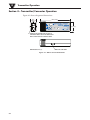
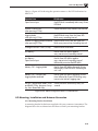
TIP: Use the plate as a template to mark the location of the mounting holes you
need to drill before installing the mounting kit onto the connector transmitter.
MOUNTING
BRACKET
MOUNTING
SCREW
SPACER
MWTC UNIT
TC
+
WIR
EL
TY
ES
PE
ST
HE
RM
M
TX
LO
BA W
TT
P
R
ES
SE
TUS
P
OC
OU
W PLE CON
TC NECTO
R
PR
ES
I/0
S
Figure 4-13. Mounting Bracket Installation
4.2.2 Mounting
When mounting your connector/transmitter, care should be taken to make sure
it is as far away from any metal objects. If nearby metal gets too close to your
connector/transmitter, it has the potential to interfere with the way the unit
radiates and may cause signal lose or possibly even the inability to communicate
at all with your receiver.
4.2.3 Installation
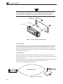
When installing your connector/transmitter it is important to position your
device in such a way as to optimize the antenna location within what’s known as
the “Fresnel Zone”.
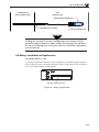
The Fresnel Zone can be thought of as a football-shaped invisible tunnel between
two locations that provides a path for RF signals between your
connector/transmitter and your receiver.
WIRELESS THERMOCOUPLE CONNECTOR
–
MWTC
TYPE
TC
TX
+
LOW
BATT
PRESS
PRESS
SETUP
I/O
®
FRESNEL ZONE
Figure 4-14. Fresnel Zone
4-11
RECEIVER
ANTENNA