1
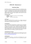
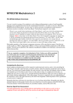
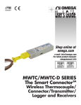
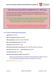
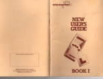
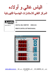
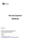
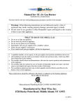
School of Aerospace, Mechanical and Mechatronic Engineering Mechatronics Laboratory Notes on Facilities These notes describe the facilities available to authorised users of the Mechatronics Laboratory, Room 330 in the Link Building. The present notes should be read in conjunction with a companion document, “Mechatronics Laboratory – Introduction.doc”. This document is available in Adobe PDF form on the Lab website, http://www.aeromech.usyd.edu.au/MTRXLAB/. Lab facilities are divided into two categories, termed “open facilities” and “closed facilities” in these notes. Open facilities are those that you can use as soon as you are within the Lab, such as the Lab Workstations. Closed Facilities are held in locked cupboards to prevent damage or theft when the Lab is unattended. You will need to surrender a form of identification to a member of academic or tutoring staff before you can use any of the closed facilities. The equipment will be signed out to you, and your card returned when you return the equipment in good condition. 1 Open Facilities: Lab Workstations The Mechatronics Laboratory is equipped with eighteen Lab Workstations. Each Workstation is designed for computer software and electronics development, and is equipped with A networked IBM-compatible computer; A Tektronix TDS 1002 two-channel digital storage oscilloscope; A power supply with two sections: a regulated supply for powering computers and electronics, and an unregulated supply for powering motors. This equipment is described in more detail below. Note that each Lab Workstation is numbered, and that you may be assigned to work at a particular Workstation. 1.1 Computers Each black computer has a Intel Core 2 Duo processor, 80 GB hard disk and 2 GB RAM. The computers are dual-boot, so that you will be prompted to select the Windows XP operating system, QNX Neutrino If no selection is made, the machine will boot into Windows XP by default. Each hard disk is formatted with 2 logical partitions. 1.1.1 MxLab Domain The computers in the Mechatronics Laboratory are members of a Windows 2003 domain called mxlab.acfr.usyd.edu.au. 1.1.2 User Windows Accounts and File Space A separate Windows account will be set up for each student enrolled in the subjects that use the Mechatronics Lab. NOTE that your Mechatronics Lab account is not the same account as your Unikey1 account or your account in the AMME PC Labs, even though they have the same names. 1 The Unikey username is also the same as a student’s literal email account name. For example, if the email address of a student named Annette Student is [email protected], Annette’s username in the Mechatronics Lab will be astu3141. 1 of 11 The account details are as follows: Username: ccccnnnn, where ‘ccccnnnn’ are the four characters and four numerals of the student’s Unikey username. Domain: mxlab Password: will be notified individually. Note that both username and password are case sensitive. You will be required to change your password the first time you log on to the system. To change your password at any subsequent time, press [Ctrl], [Alt] and [Del] simultaneously and then select [Change Password]. You must enter your old password and then the new password twice to make a successful change. Windows will confirm that the password has been changed. When selecting a password, do not use a word that can be found in any dictionary but do not choose something you can’t remember or you will be locked out. One idea is to choose a phrase that you can remember easily, such as “I went to the Mechatronics Lab today at 12 noon” and construct a password based on the first letters of each word, in this case IwttMLta12n. This password is easy to remember, but very difficult to guess (or read over your shoulder as you type it!) Once a user has logged into Windows, they will be able to run a number of applications programs, and to write files to certain protected directories (folders). These directories are located on the lab server. Table 1 summarises the locations to which Students have access. Table 1: File Locations and Shortcuts Location Data Type(s) Shortcut(s) \\mxlabserver\Users\2 An individual user’s files \\mxlabserver\Groups\3 Files shared between multiple users \\mxlabserver\Courses\ \\mxlabserver\Farnell\ C:\Documents and Settings\%USERNAME%\ Course specific information Semiconductor datasheets Windows Profile information (desktop settings, background etc.) U: My Documents (shortcut on desktop) V: (shortcut on desktop) (shortcut on desktop) Accessed via application none As an example, Annette Student’s machine configuration will be in a directory (folder) named c:\Documents and Settings\astu3141 on the local computer, while her files will be stored in U:\astu3141 on the server. The default permissions on these directories (and their subdirectories) will prevent any other user from viewing, copying or deleting the files. You should not change the permissions on these directories or any other folder or file within it – this may interfere with the correct operation of Windows. Several of the applications used in the Mechatronics Laboratory do not support UNC (Universal Naming Convention) filenames (e.g. \\mxlabserver\Users), and so drive mappings are provided to the locations where data is to be stored. Please try to remember to use U: and V: preferentially over their UNC versions to avoid these problems. 1.1.3 Access to User Accounts Before you can be granted access to the computer account created for your use in the Mechatronics Laboratory you will be required to complete a short OH&S induction for the Lab. 2 Individual users cannot create folders in this location and have access only to their own folder. Each student is provided a folder with the same name as their login name, eg. \\mxlabserver\Users\astu3141 for Annette Student. 3 Users can create folders here and set permission to allow others to access the files. See details later in this document. 2 of 11 You must also agree to comply with the Conditions of Use of the University’s ‘Policy on the Use of University Information and Communication Technology Resources (ICT Resources).’ This document is available on the Internet at http://www.usyd.edu.au/hr/policydev/ict_resources_policy.pdf 1.1.4 Security Settings and “Shares” In addition to their “private” file space, students can create folders designed for storing group work files. Any student can create new folders within the (\\mxlabserver\Groups) folder (the V: drive) on the lab server. The default permissions for any folders created in this directory will allow the user who created the folder to have full control over the folder and all the files and folders within it. In this context, “full control” means the ability to permit or deny access by any other user. Before they can access a particular group work folder, other students will need to be added to the permissions for that folder. The creator of the folder is the only user who can change the permissions of other users. The permissions for the user who created the folder do not have to be modified to allow them to use the files correctly. To change those users who have access to a folder of file, right click on the directory or file and select [Properties]. Navigate to the [Security] tab: this will display the current permissions set for the item. In the left part of Figure 1, for example, the folder V:\FarrellyBros initially allows access by the user (dumb) who created the item, by CREATOR OWNER (the user who created the folder), and the machine Administrators. To view the specific access rights of different users, click on their user name and see which boxes have been ticked. Special permissions can be set, and can only be seen if you click on the [Advanced] button. Figure 1: Permissions dialogues - before changes (left) and after changes (right) To allow another user to access the folder, click on the [Add] button, enter the user name into the box and click [OK]. They will be added to the list and will, by default, be given enough rights to read the files and folders, but not to edit them or to create others. Tick the boxes for the rights you wish to give the user. If you want the new user to be able to work on the files with the same permissions as the creator, you must tick all the available boxes to give them full control over the folder. The right part of Figure 1 shows the permissions after the user dumber has been added with full control. 3 of 11 1.1.5 File Transfer and Remote Login 1.1.5.1 From Within the Laboratory From within the laboratory all files will be available on the fileserver in the share locations outlined above. As no files should be stored locally, there is no need to access the files on another lab machine. 1.1.5.2 From Outside the Laboratory but Within the University (includes VPN) The mxlabserver file shares can be accessed from any computer within the University by using a “fully-qualified” machine name for the location. For example, whereas within the Lab you could access the Groups folder on the server using \\mxlabserver\Groups as the location, to access it from outside the lab you need to use \\mxlabserver.mxlab.acfr.usyd.edu.au\Groups. This tells the computer to look for the machine mxlabserver in the correct place. The fullyqualified folder location can either be typed into the top of an Explorer window or used as the location for a mapped network drive. 1.1.5.3 From Outside the University The mxlab domain exists as a private part of the University’s network and so cannot be accessed from outside the University except by 1. Connecting to the University’s VPN server – or – 2. Connecting to the University’s Wireless Network, and hence the VPN server. If you live on campus you will be connected to a network inside the University. Given these conditions, you can access the Windows shares on either the server or on individual computers as outlined below. If you connect to the Internet from home, try using the University’s VPN server. Apart from that, the only method for transferring files between the Lab and an outside computer is via your student email account, or on a USB drive. Windows 1. Use Windows Explorer to connect by using a UNC name in the Explorer address window: \\mxlabserver.mxlab.acfr.usyd.edu.au 2. Enter your username as mxlab\Username and password when prompted. Linux (thanks Rob) 1. The cleanest way to access Windows shares in the mxlab from Linux is to mount the remote share, so that you can access the files on the remote system using your normal GUI file browser. You must be root to do this on most systems. Type the following on one line mount -t smbfs -o username=Username,workgroup=mxlab //mxlabserver.mxlab.acfr.usyd.edu.au/groups /mnt/mymount/ 2. The alternative is to access the remote system using smbclient. Once you have run the smbclient command with the appropriate options you will have ftp-like access to the Windows share. Type the following on one line: smbclient //mxlabserver.mxlab.acfr.usyd.edu.au/groups -W mxlab -U Username Of course, you will replace Username with your actual mxlab Username, won’t you… Macintosh We don’t know, as no one here uses a Mac. If anyone does know, please tell us. 4 of 11 1.1.6 Virus Protection Each PC is protected by Symantec Antivirus, which is configured to intercept and quarantine viruses. Virus definitions are automatically updated as they become available from Symantec, and each machine is scanned daily. 1.1.7 Windows Updates and Patches Each machine in the laboratory is connected to an automatic updating service. This means that operating system patches are automatically installed. Together with the automated virus updating and scanning, this represents current “best practice” for avoiding virus or other attacks. 1.1.8 Printing There are no printers in the Mechatronics Lab. Undergraduate students who have accounts in the domain uglab.aeromech.usyd.edu.au can print to the printers hosted in that domain. The printers are physically located in Rooms S322 and S345 in the Mechanical Engineering Building. 1.1.9 Running DOS Application Software Some of the applications programs run from a command line prompt within a DOS shell4. Each of these DOS application is run by a batch file that is in the subdirectory C:\Bat of each machine. This directory is in the Windows PATH variable of every user, so that each console application can be executed from any user directory. Each batch file does a number of things: SETs any environment variables required by the particular application; sets a PATH suitable for the application; runs the application, and then; resets PATH to the value it had before the batch file was run; clears any environment variables that were SET. 1.1.10 Personal Batch Files If you want to create and use your own batch files, your batch files must do at least the following two things before they terminate, even if they terminate with errors: 1. clear any environment variables that are SET by the batch file; 2. reset PATH to its value before the batch file. 1.1.11 Computer and Network Maintenance The computers and network in the Mechatronics Lab are configured and maintained by staff from the Australian Centre for Field Robotics. If you discover computer or network faults, please report them by email to [email protected]. 4 They are “console applications” 5 of 11 1.2 Oscilloscopes Each Lab Workstation is equipped with Tektronix TDS 1002 two-channel digital storage oscilloscope, shown in Figure 2. These oscilloscopes have a bandwidth of 60MHz, and a sampling rate of 1 GS/sec. They are excellent (and expensive) tools. Please note that the scope probes (leads) are never left in the Lab. When you need to use a scope, you will have to check out one or two scope probes. Figure 2: Front panel of a Tektronix TDS 1002 oscilloscope. It is most important for you to learn to use a scope properly, and to get into the habit of using a scope to monitor signals. The amount of information that you can obtain from a scope is far greater than that available from a DMM5. You are expected to learn how to use a scope proficiently. If you can't use a scope effectively, read the Shortish Guide to Using an Oscilloscope, available in PDF form from the Lab website, http://www.aeromech.usyd.edu.au/MTRXLAB/. In fact, we insist that you read it anyway, before using the scope. The full TDS 1002 oscilloscope manual is also available in PDF form from the Lab web site. 1.3 Power Supplies Each Lab Workstation is equipped with a power supply having two independent sections. The front panel of the power supply is shown in Figure 3. Each unit has two independent supplies: a regulated supply for powering computers and electronics, and an unregulated supply for powering motors. The ratings of the two supplies are given in Table 2. Figure 3: Front panel of the Mechatronics Lab bench power supplies. 5 Digital multimeter. 6 of 11 Table 2: Lab power supplies - terminals and their ratings. Unregulated Supply (to the left) Black Terminals: +0V DC White Terminals: +12V DC, 1.5 A Yellow Terminals: –12V DC, 1.5 A Regulated Supply (to the right) Black Terminals: +0V DC Red Terminals: +5V DC, 2 A White Terminals: +12V DC, 200mA Yellow Terminals: –12V DC, 200mA There are two important things to note about the power supplies: The +0V DC terminals of the regulated supply and the unregulated supply will be at different potentials unless you connect them together. All outputs of the two supplies are protected by Polyfuses. A polyfuse is a resistive element with a positive temperature coefficient. When it heats up (due to internal I2R losses in an over-current state) its resistance increases by several orders of magnitude in a few hundred milliseconds, limiting current flow. If a power supply output voltage should go to zero, turn off the power supply and wait for a minute or two. The Polyfuse should reset automatically. 2 Closed Facilities – Hand Tools and Test Instruments A number of hand tools and electronic test instruments are available for you to use as required. This section contains notes on the function, and safe usage of most of the instruments. Please read carefully, and if in doubt, ask. Operating manuals are available for all of the instruments, and must be read before operating any instrument that you are unfamiliar with. 2.1 Loan Procedure To use any of the Lab’s “closed facilities” you must first borrow them. To borrow any of the resources, approach a course Tutor or Lecturer, and ask. If the resource is available for loan, it will be exchanged for some form of identification provided by you. Any additional resources that you borrow will also be associated with your identification. When you have returned all of the resources on loan to you in good condition, you may have your identification back. 2.2 Oscilloscope Probes These are good quality scope probes which will cost you $218.00 (each probe) to replace if you lose or damage them through either misuse or misbehaviour. They are to be used only for probing circuits. Please be careful and treat them gently. 2.3 Toolkits Toolkits may be available for loan to students, but may not be taken out of the Lab. A better idea is to buy your own small took kit. Each Lab toolkit contains: Digital multimeter with 2 probes (see notes in section 2.4) Wire cutters: for cutting copper wire only, up to 0.8 mm diameter. Do not use to cut steel wire, such as paperclips. With a little practice, these can also be used to strip insulation from wires quickly. Wire strippers: designed for stripping plastic insulation from wires. Flat jaw pliers: for bending and forming component leads, and holding stuff. Small flat screwdriver: for screw terminals on some boards, and for lifting ICs from sockets and solderless breadboard. IC extraction tool: don’t lift ICs out of solderless breadboard with your fingers – you will end up with a row of holes in your thumb, and bent IC leads! Test leads (1 set): for connecting to PCB headers or sockets. Power leads (1 set), or Plug pack, depending on the work that you are doing. 7 of 11 A tool kit will generally be loaned for one lab session only. Any tools missing or damaged through misuse when the tool kit is returned must be replaced at the expense of the student who borrowed the toolkit. 2.4 Digital Multimeter (in toolkits) The digital multimeter, or DMM, is a versatile multi-purpose test instrument that can measure DC and AC voltage, current, resistance, etc. To use, turn on; set function (volts, ohms, etc.) to the highest range, to minimise the risk of damage. Touch probes to circuit under test; reduce range as appropriate. Turn the meter off when you have finished with it, to conserve batteries. DANGER! The multimeters that are provided in the Lab toolkits are inexpensive models that are not designed for industrial use. Never use them for measuring 240V AC mains electrical circuits. Some cautions about using DMMs: A DMM is a static instrument – it shows only a stationary or time-averaged reading, and cannot show a signal changes with time. For this reason, DMM readings can often be misleading. Take a little time to learn to use an oscilloscope correctly – it is quite simple. The principal use of a DMM is measuring quantities that are known to be constant in time – checking component values, setting DC voltages, etc. Measure voltage differences with the meter in parallel to the circuit to be measured, and current with the meter in series with the circuit. A DMM measures resistance by injecting a small, known, current into the circuit under test. You must therefore be cautious when attempting to measure the resistance of a device that is in a circuit, and when interpreting the “resistance” reading displayed by the meter. You may need to remove (one leg of) the device from the circuit to measure the resistance. Never measure a voltage with the DMM set on Ohms – this will destroy the DMM. For example, never try to measure the resistance of a battery!!! Never measure the “resistance” of an IC – it just doesn’t make sense… The integrity of a diode can be tested using a DMM set to the lowest resistance range. Recall that a diode conducts when forward biased, and not when reverse biased, so that the “resistance” of a diode should be very large in one direction and very small in the other. Otherwise, it’s not really a diode… A BJT is really just two diodes in one package with three leads… 2.5 Solderless Breadboards These are used for rapidly prototyping circuits. Reasonable results can be achieved, although the significant capacitance of the breadboard itself, and the (often long) wires used in prototyping mean that breadboards are not useful for high-speed or low-noise circuits. They also cannot be used for power circuitry. 2.5.1 Rules for Breadboard Use Use only single-core insulated wire, with a core diameter of 0.7 mm ("bell wire"). If multistranded wire is used, strands break off inside the breadboard, causing short circuits and trouble for us all. Never force oversize component pins (e.g. wire-wrap sockets) into the sockets. This permanently damages the sockets, and each breadboard costs about $85 (!!). Never breadboard circuits that contain discrete or IC power components such as power transistors, regulators, etc. The breadboard will be damaged by the heat generated by the I2R losses where the component leads are inserted. 8 of 11 2.5.2 Breadboarding a Circuit First, draw a circuit diagram showing all components, signal names and pin numbers. A good circuit diagram will simplify the wiring, and help immensely with troubleshooting. Think about the placement of all components before you start to build the circuit, then place all components. Place the ICs with pin 1 oriented in the same direction (usually the top left corner). Do not forget to place any mass termination connector(s) required. Place connectors and trim pots near the outside of the breadboard for ease of access. Establish power supply buses (+0V, +5V, plus 12V if required) by connecting the long lines on the sides of the breadboard to the binding posts. In the Lab we use the colour code Red: + 5V DC White: +12V DC Black: + 0V DC Yellow: –12V DC. Establish power supply to all devices. This will help your orientation in the circuit, and will ensure that you do not forget to power a device. Use the same wire colours as above. Do not forget to add sufficient bypass capacitors (0.01 to 0.1 μF tantalum chip capacitors). Connect the other signals: data, address, I/O lines. Use different colours to help in tracing and troubleshooting the circuit. For example, data bit 0 is blue, bit 1 is green, etc. Check the whole circuit. 2.5.3 Initial Power-up Check the whole circuit again. Set any trim pots to sensible starting values, usually mid-range if the circuit design is sensible. Power the circuit up, ensuring that all voltages (+0V, +5V, 12V if required) are applied simultaneously. Carefully touch the component packages (not the leads) to check that none of the chips are overheating. Switch off immediately if any temperatures seem excessive. If everything is OK so far, check all the power supply pins with an oscilloscope to make sure that power is available everywhere it should be. Use the scope so that you can see timevarying signals (e.g. noise) if they are present! Check to see if clock pulses are present everywhere that they should be. Finally, apply valid input signals, and start to check that everything is working properly. 2.6 Crimp Tool We use the AMP “Modu” type crimp contacts and contact carriers for some semi-permanent project work in the Lab. Several hand-operated crimp tools are available to make these connectors. You will need a small amount of instruction on the easiest way to use this tooling. 2.7 Logic Probe A logic probe is a simple test instrument that senses the logic state of a circuit node. CAUTION! Power up the circuit first! Logic probes have a (small) potential that can damage the circuit under test if the circuit is not powered up during testing. To use a logic probe, first connect the black lead to +0V DC, then the red lead to +5V DC power source. Touch the probe to a point in the powered-up TTL logic circuit: the LEDs & audiable tone indicate the logic state (high, low, or pulsing) at that point in the circuit. 2.8 Logic Pulser A logic pulser is a test instrument that senses the logic state (high or low) at a circuit node, and injects a pulse of the opposite logical state into the circuit. The pulse injected can be either a single 9 of 11 pulse, or a 5 Hz pulse train. A logic pulser is useful for injecting exactly one pulse into a circuit (no switch bounce) or for tracing a signal through a board. To use, first connect black lead to +0V DC, and the red lead to +5V DC power source. Touch the probe tip to a powered-up TTL logic circuit, and press the button. 2.9 Function Generator We have several Hung Chang model 8205A Sweep Function Generators. These can generate frequency-swept or stationary square, sine or triangle waves at frequencies up to 2MHz. They are useful for generating quick-and-dirty signals, but are not stable enough to act as clocks, etc. 2.10 Frequency Counter We have a Yokagawa FC-863 Frequency Counter. 2.11 Ango EPROM Eraser This device consists of an ultraviolet tube mounted above a small sliding tray. To erase a (UV) EPROM, remove any label from the quartz window and place the EPROM in the tray, with its legs pushed into the conductive foam. Turn on the eraser. The eraser will erase (set all bits to 1) a few EPROMs in about 40 minutes. Some cautions: Don't look at the UV radiation – it can permanently damage the eye; Turn the eraser off at the power when finished. 3 Electronic Components We keep a small stock of passives (resistors, capacitors, etc.), analogue (so-called “linear”) devices (transistors, op-amps, timers, comparators), digital ICs (particularly 74LSxx, 74HCxx, 74ACxx, and some 74xx family ICs), optoelectronics (LEDs, 7-segment displays), and some hardware (push buttons, switches, etc.). Most of the components that we keep are listed on the Lab web site, along with links to data sheets in PDF format. If you need to use components, identify what you will need, then speak to a Tutor or Lecturer. You may be asked to justify your selection with a circuit diagram and/or design calculations. When using components from our stock, please: If you find that you don’t need to use something, give it to a Tutor or Lecturer to go back in the component bins straight away. Otherwise, it will get kicked around on the bench and, eventually, thrown out. When you blow something up, own up!! Don’t worry – we’ve done it too... If the chip is testable (TTL logic gates, RAM), test it! If the chip is dead, fold its legs over and throw it away. Never allow a dead component to be put back into the component bins – you may be the unfortunate person who takes it out to use!! 3.1 Static and Component Handling Precautions Some ICs are static-sensitive, and can be destroyed through careless handling. Even worse, static damage is cumulative – damage that occurs in handling may not be enough to destroy the device, but a small amount of additional damage may end the device’s life. This scenario is particularly disastrous if it occurs in the field during the warranty period… You should be particularly careful with analogue CMOS – A/D converters are especially prone to damage. Before handling a staticsensitive device, you should touch your hand to ground, or at least to a large capacitance, to discharge any accumulated static. Once the device is in a circuit and powered, no special precautions need be taken. 10 of 11 Aside: Actually, one should use a conductive wrist strap earthed through a 1M resistor, together with conductive tools & work surface. This is done in production. Also, while we are talking about production, be aware that static damage is cumulative. If the proper anti-static precautions are not taken, a chip can get “zapped” during assembly, but still function well enough to pass testing. It gets delivered in a product, and then fails in the field. Ouch. 3.2 Importance of Power Supply Another way that a chip may be destroyed is to apply an input (analogue or digital) before the chip’s power supply is established. In particular, if you apply an input to an op-amp before both (+ and –) power supplies are connected, or if the supply voltages are unequal, the op-amp may be destroyed when the input voltage exceeds either of the op-amp’s power supply rail voltages. This is one good reason for always connecting the power supply first when bread boarding a circuit. 4 Components Data Sheets and Reference Manuals When working with electronics, the only reliable reference is the device manufacturer's data sheets, and even then you need to be careful. All component manufacturers provide data sheets on their web sites, invariably in Adobe portable document format (PDF). We have tried to provide links on the Lab web site to data sheets for each device that you are likely to use. You will have to become very familiar with reading these data sheets. Some other resources include: PDF data sheets held on the Lab file server. These can be accessed through the Programs menu on each Lab computer. Component reseller's catalogues (and web sites) – Farnell Components, RS Components, Jaycar Electronics, Altronics, Dick Smith Electronics. These have a lot of useful information in them. See in particular the information in the back of the Dick Smith catalogue. Component manufacturer’s web sites – these are linked from the Mechatronics Lab web site, http://www.aeromech.usyd.edu.au/MTRXLAB/. 5 Document Improvement Should you discover errors, omissions or unclear information in this document, please report these deficiencies by email to [email protected] so that this document can be improved. David Rye, Richard Grover, Steve Scheding, Bella Wong July 2002 Revised March 2012 11 of 11