1
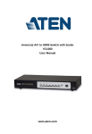
2/4-Port DVI Dual Link Splitter with Audio VS172 / VS174 User Manual www.aten.com VS172 / VS174 User Manual FCC Information Warning: This is a class A product. In a domestic environment this product may cause radio interference in which case the user may be required to take adequate measures. FEDERAL COMMUNICATIONS COMMISSION INTERFERENCE STATEMENT This equipment has been tested and found to comply with the limits for a Class A digital device, pursuant to Part 15 of the FCC Rules. These limits are designed to provide reasonable protection against harmful interference when the equipment is operated in a commercial environment. This equipment generates, uses, and can radiate radio frequency energy and, if not installed and used in accordance with the instruction manual, may cause harmful interference to radio communications. Operation of this equipment in a residential area is likely to cause harmful interference in which case the user will be required to correct the interference at his own expense. FCC Caution: Any changes or modifications not expressly approved by the party responsible for compliance could void the user's authority to operate this equipment. RoHS This product is RoHS compliant. SJ/T 11364-2006 The following contains information that relates to China. ii VS172 / VS174 User Manual User Information Online Registration Be sure to register your product at our online support center: International http://eservice.aten.com Telephone Support For telephone support, call this number: International 886-2-8692-6959 China 86-10-5255-0110 Japan 81-3-5615-5811 Korea 82-2-467-6789 North America 1-888-999-ATEN ext 4988 United Kingdom 44-8-4481-58923 User Notice All information, documentation, and specifications contained in this manual are subject to change without prior notification by the manufacturer. The manufacturer makes no representations or warranties, either expressed or implied, with respect to the contents hereof and specifically disclaims any warranties as to merchantability or fitness for any particular purpose. Any of the manufacturer's software described in this manual is sold or licensed as is. Should the programs prove defective following their purchase, the buyer (and not the manufacturer, its distributor, or its dealer), assumes the entire cost of all necessary servicing, repair and any incidental or consequential damages resulting from any defect in the software. The manufacturer of this system is not responsible for any radio and/or TV interference caused by unauthorized modifications to this device. It is the responsibility of the user to correct such interference. The manufacturer is not responsible for any damage incurred in the operation of this system if the correct operational voltage setting was not selected prior to operation. PLEASE VERIFY THAT THE VOLTAGE SETTING IS CORRECT BEFORE USE. iii VS172 / VS174 User Manual Package Contents The VS172 / VS174 2/4-Port DVI Dual Link Splitter with Audio package consists of: 1 VS172 / VS174 2/4-Port DVI Dual Link Splitter with Audio 1 Power Adapter 1 User Instructions* Check to make sure that all the components are present and that nothing got damaged in shipping. If you encounter a problem, contact your dealer. Read this manual thoroughly and follow the installation and operation procedures carefully to prevent any damage to the unit, and/or any of the devices connected to it. * Features may have been added to the VS172 / VS174 since this manual was printed. Please visit our website to download the most up-to-date version. © Copyright 2012–2013 ATEN® International Co., Ltd. Manual Date: 2013-07-03 ATEN and the ATEN logo are registered trademarks of ATEN International Co., Ltd. All rights reserved. All other brand names and trademarks are the registered property of their respective owners. iv VS172 / VS174 User Manual Contents FCC Information . . . . . . . . . . . . . . . . . . . . . . . . . . . . . . . . . . . . . . . . . . . . . ii SJ/T 11364-2006. . . . . . . . . . . . . . . . . . . . . . . . . . . . . . . . . . . . . . . . . . . . . ii User Information . . . . . . . . . . . . . . . . . . . . . . . . . . . . . . . . . . . . . . . . . . . . .iii Online Registration . . . . . . . . . . . . . . . . . . . . . . . . . . . . . . . . . . . . . . . .iii Telephone Support . . . . . . . . . . . . . . . . . . . . . . . . . . . . . . . . . . . . . . . .iii User Notice . . . . . . . . . . . . . . . . . . . . . . . . . . . . . . . . . . . . . . . . . . . . . .iii Package Contents. . . . . . . . . . . . . . . . . . . . . . . . . . . . . . . . . . . . . . . . . . . iv Contents . . . . . . . . . . . . . . . . . . . . . . . . . . . . . . . . . . . . . . . . . . . . . . . . . . . v About this Manual . . . . . . . . . . . . . . . . . . . . . . . . . . . . . . . . . . . . . . . . . . . vi Conventions . . . . . . . . . . . . . . . . . . . . . . . . . . . . . . . . . . . . . . . . . . . . . . . vii Product Information. . . . . . . . . . . . . . . . . . . . . . . . . . . . . . . . . . . . . . . . . . vii 1. Introduction Overview . . . . . . . . . . . . . . . . . . . . . . . . . . . . . . . . . . . . . . . . . . . . . . . . . . . 1 Features . . . . . . . . . . . . . . . . . . . . . . . . . . . . . . . . . . . . . . . . . . . . . . . . . . . 2 Requirements . . . . . . . . . . . . . . . . . . . . . . . . . . . . . . . . . . . . . . . . . . . . . . . 3 Consoles . . . . . . . . . . . . . . . . . . . . . . . . . . . . . . . . . . . . . . . . . . . . . . . . 3 Computers . . . . . . . . . . . . . . . . . . . . . . . . . . . . . . . . . . . . . . . . . . . . . . . 3 Cables . . . . . . . . . . . . . . . . . . . . . . . . . . . . . . . . . . . . . . . . . . . . . . . . . . 3 Components . . . . . . . . . . . . . . . . . . . . . . . . . . . . . . . . . . . . . . . . . . . . . . . . 4 Front View . . . . . . . . . . . . . . . . . . . . . . . . . . . . . . . . . . . . . . . . . . . . . . . 4 Rear View . . . . . . . . . . . . . . . . . . . . . . . . . . . . . . . . . . . . . . . . . . . . . . . 5 . . . . . . . . . . . . . . . . . . . . . . . . . . . . . . . . . . . . . . . . . . . . . . . . . . . . . . .5 2. Hardware Setup Grounding . . . . . . . . . . . . . . . . . . . . . . . . . . . . . . . . . . . . . . . . . . . . . . . . . . 7 Single Stage Installation . . . . . . . . . . . . . . . . . . . . . . . . . . . . . . . . . . . . . . . 8 Cascading . . . . . . . . . . . . . . . . . . . . . . . . . . . . . . . . . . . . . . . . . . . . . . . . . . 9 3. Operation Overview . . . . . . . . . . . . . . . . . . . . . . . . . . . . . . . . . . . . . . . . . . . . . . . . . . 11 RS-232 Serial Interface. . . . . . . . . . . . . . . . . . . . . . . . . . . . . . . . . . . . . . . 11 Configuring the Serial Port . . . . . . . . . . . . . . . . . . . . . . . . . . . . . . . . . 11 Reset Commands . . . . . . . . . . . . . . . . . . . . . . . . . . . . . . . . . . . . . 18 Verification. . . . . . . . . . . . . . . . . . . . . . . . . . . . . . . . . . . . . . . . . . . . . . 18 Appendix Safety Instructions. . . . . . . . . . . . . . . . . . . . . . . . . . . . . . . . . . . . . . . . . . . 19 General . . . . . . . . . . . . . . . . . . . . . . . . . . . . . . . . . . . . . . . . . . . . . . . . 19 Technical Support . . . . . . . . . . . . . . . . . . . . . . . . . . . . . . . . . . . . . . . . . . . 21 International. . . . . . . . . . . . . . . . . . . . . . . . . . . . . . . . . . . . . . . . . . . . . 21 North America . . . . . . . . . . . . . . . . . . . . . . . . . . . . . . . . . . . . . . . . . . . 21 Specifications . . . . . . . . . . . . . . . . . . . . . . . . . . . . . . . . . . . . . . . . . . . . . . 22 Limited Warranty . . . . . . . . . . . . . . . . . . . . . . . . . . . . . . . . . . . . . . . . . . . . 22 v VS172 / VS174 User Manual About this Manual This User Manual is provided to help you get the most from your VS172 / VS174 system. It covers all aspects of installation, configuration and operation. An overview of the information found in the manual is provided below. Introduction, introduces you to the VS172 / VS174 system. Its purpose, features and benefits are presented, and its front and back panel components are described. Hardware Setup, describes how to set up your VS172 / VS174 installation. The necessary steps are provided. Operation, explains the fundamental concepts involved in operating the VS172 / VS174 through the RS-232 serial interface. An Appendix, provides specifications and other technical information regarding the VS172 / VS174. vi VS172 / VS174 User Manual Conventions This manual uses the following conventions: Monospaced Indicates text that you should key in. [] Indicates keys you should press. For example, [Enter] means to press the Enter key. If keys need to be chorded, they appear together in the same bracket with a plus sign between them: [Ctrl+Alt]. 1. Numbered lists represent procedures with sequential steps. ♦ Bullet lists provide information, but do not involve sequential steps. → Indicates selecting the option (on a menu or dialog box, for example), that comes next. For example, Start → Run means to open the Start menu, and then select Run. Indicates critical information. Product Information For information about all ATEN products and how they can help you connect without limits, visit ATEN on the Web or contact an ATEN Authorized Reseller. Visit ATEN on the Web for a list of locations and telephone numbers: International http://www.aten.com North America http://www.aten-usa.com vii VS172 / VS174 User Manual This Page Intentionally Left Blank viii Chapter 1 Introduction Overview Various industry sectors have come to rely on audio-visual displays to broadcast real-time information, advertise products or conduct trainings. To further extend the reach of these video systems, there is a need for splitters that can multiply the number of screens without affecting video quality. The 2/4-Port DVI Dual Link Splitter with Audio charts a new direction in multimedia functionality by combining DVI quality video and audio. They take the signals from an audio/video source and replicate them to two (VS172) / four (VS174) audio/video outputs. This 2-port / 4-port video splitter uses dual link technology, which offers high bandwidth capacity for added transmission power and faster refresh rates, thereby providing better video quality of viewing resolutions up to 2560 x 1600. The built-in bi-directional RS-232 port on the rear panel allows the splitter to be controlled through a Control Unit, PC, and/or home automation/home theater software package for complete system integration. In addition, you can switch ports, enable/disable EDID mode, mute the audio or upgrade the firmware version locally from one console. The VS172 / VS174 is easy to operate and can be cascaded to three levels and handle up to 8 (VS172) / 64 monitors (VS174), which makes them the ideal solution for situations such as: a) Broadcasting video information to the public (news headlines, stock prices, airline and train schedules, etc.) b) Company training facilities c) Classroom instruction The VS172 / VS174 provides the best audio-visual solution for a range of scenarios, from informal situations to corporate presentations. 1 VS172 / VS174 User Manual Features Displays DVI audio/video to multiple DVI-compatible monitors or projectors Superior video quality – up to 2560 x 1600 @ 60Hz, and 1080P Cascadable to 3 levels – provides up to 8/64 video signals Audio enabled Features RS-232 serial port for command controls RS-232 Chain Control – use RS-232 commands to control cascaded devices via a DVI cable EDID Expert – selects the optimum EDID settings via RS-232 Note: The VS172 / VS174 AP and GUI operation instructions can be downloaded from the ATEN website (www.aten.com). 2 1. Introduction Requirements The following equipment is required for a complete VS172 / VS174 installation: Consoles A DVI display that matches the computer’s DVI display card that is capable of the highest resolution that you will be using on the DVI output. Speakers for audio output (optional) Computers The following equipment must be installed on any computer that acts as a source of DVI content: A DVI-I or DVI-D display port Note: The quality of the display is affected by the quality of the DVI display card. For best results, we recommend you purchase a high quality product. An audio out port (optional – for audio accompaniment to the display) Cables Two (VS172) or four (VS174) sets of DVI cable are required to properly operate this DVI Switch (not included). Note: 1. Cables are not included in this package. Since the quality of the display is affected by the quality and the length of the cables, we strongly recommend that you purchase high quality cables. Contact your dealer to purchase the correct cable sets for your switch. 2. There are three types of DVI signals. The cable type must match the type of signal being used by the DVI source and the DVI display. 3 VS172 / VS174 User Manual Components Front View 1 No. Component 2 3 Description 1 Power/Standby button Use this button to turn on the unit or wake it from standby mode. 2 Power LED Lights green to indicate that the VS172 / VS174 is receiving power and is up and running. Lights orange to indicate that the VS172 / VS174 is in standby mode. 3 Activity LED Lights to indicate that there is a working DVI connection to the computer Note: The VS174’s front panel is shown on this page. It is similar to the front panel of VS172. 4 1. Introduction Rear View VS172 4 5 1 2 3 VS174 4 5 1 No. 2 Component 3 Description 1 Power Jack The power adapter cable plugs in here. 2 A/V Input Section The cables from your source device’s DVI video and speaker ports plug in here. 3 A/V Output Section The cables from your DVI monitors and speakers plug in here. 4 Grounding The grounding wire (used to ground the unit) attaches here. Note: The grounding wire is not included in this package. Contact your dealer for more information. 5 RS-232 Serial Port This is the serial remote port for output source selection and high-end system control, including firmware upgrade. 5 VS172 / VS174 User Manual This Page Intentionally Left Blank 6 Chapter 2 Hardware Setup 1. Important safety information regarding the placement of this device is provided on page 19. Please review it before proceeding. 2. Make sure that the power to all devices connected to the installation are turned off. 3. Make sure that all devices you will be installing are properly grounded. Grounding To prevent damage to your installation it is important that all devices are properly grounded. 1. Use a grounding wire to ground the VS172 / VS174 by connecting one end of the wire to the grounding terminal, and the other end of the wire to a suitable grounded object. 2. Make sure that the computer(s)/device(s) that the VS172 / VS174 connects to are properly grounded. Note: The grounding wire is not included in the package. Please contact your dealer for the appropriate cable. 7 VS172 / VS174 User Manual Single Stage Installation Refer to the installation diagram (the numbers in the diagram correspond to the numbers of the steps) and do the following: 1. Use a male-to-male DVI cable to connect your source device’s DVI port to the VS172 / VS174’s Video In port. 2. Use a male-to-male audio cable to connect your source device’s speaker port to the VS172 / VS174’s Audio In port. 3. Plug your DVI monitors and speakers into the A/V Out ports. 4. (Optional) To edit the VS172 / VS174 system settings through the RS-232 port, connect the hardware / software controller here. 5. Plug the power adapter that came with your switch into an AC power source, then plug the power adapter cable into the switch’s Power Jack 3 4 5 1 2 or Note: The 4-port VS174 panel images are used for illustrations throughout this manual. 8 2. Hardware Setup Cascading To provide even more audio/video display, additional units can be cascaded from the VS172 / VS174’s A/V Out ports. Simply use additional male to male DVI and audio cables to connect an A/V Out port on the parent splitter to the A/V In port of the child splitter. Recommended distances between devices in all cascade levels/stages for transmitting a high resolution signal are as follows: Source to VS172 / VS174: 1.8 m VS172 / VS174 to VS172 / VS174: 5 m VS172 / VS174 to display: 5 m First stage unit Second stage unit/s Third stage unit/s 9 VS172 / VS174 User Manual This Page Intentionally Left Blank 10 Chapter 3 Operation Overview The 2/4-Port DVI Dual Link Splitter with Audio offers easy and flexible source device selection through the RS-232 serial interface. RS-232 Serial Interface The VS172 / VS174’s built-in bi-directional RS-232 serial interface allows system control through a high-end controller, such as a PC or home automation/home theater software. Configuring the Serial Port The controller’s serial port should be configured as follows: Baud Rate 19200 Data Bits 8 Parity None Stop Bits 1 Flow Control None 11 VS172 / VS174 User Manual Switch Port Commands The formula for Switch Port commands are as follows: Switch Command + Output + Port + Control [Enter] For example, to switch output port to port 02, type the following: sw o02 on [Enter] The following tables show the possible values and formats for the Output command, Port number and Control: Command Description sw Switch command Output Description o Output command Port Description yy 01-04 port (default is 01) * All output ports Control Description on Turn on the VS172 / VS174 off Turn off the VS172 / VS174 Note: Each command string can be separated with a space. The Port command string can be skipped and the default value will be used. The following table shows the available command list: Command Output Port Control Enter Description sw o yy on [Enter] Turn on (Display out) for output port sw o yy off [Enter] Turn off (No output) for output port sw o * on [Enter] Turn on (Display out) for all ports sw o * off [Enter] Turn off (No output) for all ports 12 3. Operation Command for Cascaded Splitters Serial port commands for cascaded splitters require identifying the chain of ports to which the target device is connected. The formula for Switch Port commands are as follows: Switch Command + Output + Port + Port at first stage + Port at second stage + Control [Enter] First stage unit Second stage unit/s Third stage unit/s Target output For the example above, the command for switching to the target output Port 1 of the splitter connected to Port 1 at the second stage of the cascade, which, in turn, is connected to output Port 2 at the first stage unit, is as follows: sw o01-02-01 on [Enter] This cascade command format is applied to Mute Commands, page 15, Read Commands, page 17, and Reset Commands, page 18. However, this is not applicable to EDID commands, which apply only to the first stage unit splitter, as well as the Firmware commands. 13 VS172 / VS174 User Manual EDID Commands Extended Display Identification Data (EDID) is a data format that contains a display's basic information and is used to communicate with the video source/ system. You can set up which EDID mode the VS172 / VS174 uses with the following command: EDID Command + Control [Enter] The EDID commands work only for the first stage unit when cascading VS172 / VS174 units. The following tables show the possible values and formats for the Control command: Command Description edid Enable EDID selection Control Description port1 Implement the EDID of the connected display to Port 1, and pass it to the video source (default) auto Implement the EDID of all connected displays. The VS172 / VS174 uses the best resolution for all displays default Implement ATEN’s default EDID The following table shows the available command list: Command 14 Control Enter Description edid port1 [Enter] The EDID from Port 1 is passed to the video source edid auto [Enter] The VS172 / VS174 implements the EDID of all connected displays and uses the best resolution for all displays (default) edid default [Enter] ATEN’s default EDID is passed to the video source 3. Operation Mute Commands Enable or disable audio coming from the output port(s) using the following command: Mute Command + Output + Port + Control [Enter] The following tables show the possible values and formats for the Output, Port and Control commands: Command Description mute Enable / Disable audio of output port(s) Output Description o Output command Port Description yy Identify the output port to which the mute command applies. * All output ports Control Description on Mute on; audio from output port is disabled off Mute off; audio output enabled (default) Note: Each command string can be separated with a space. The following table shows the available command list: Command Output Port Control Enter Description mute o yy on [Enter] No audio from port mute o * on [Enter] No audio from all ports mute o yy off [Enter] Audio enabled for port mute o * off [Enter] Audio enabled for all ports 15 VS172 / VS174 User Manual Firmware Commands Upgrade the firmware by using this command: Upgrade Command + Control [Enter] The firmware upgrade command works only for the unit connected to the local PC or hardware / software controller. In order to upgrade the firmware of other VS172 / VS174 units in the cascade, manually connect them, one by one, to the local PC. The following tables show the possible values and formats for the Control command: Command Description upgrade Starts the firmware upgrade process The following table shows the available command list: 16 Command Enter Description upgrade [Enter] Firmware upgrade process starts 3. Operation Read Commands View information from the device using the following command: Read Command + Port + Control [Enter] The following tables show the possible values and formats for the Port and Control commands: Command Description read Reads and displays information from the VS172 / VS174 o Output port Port Description yy Displays the status of the port * Displays status of all ports Control Description version Displays the firmware version of the VS172 / VS174 edid Displays the EDID mode setting of device 01 video Displays the video status (on/off) audio Displays the audio status (on/off) Note: Each command string can be separated with a space. The following table shows the available command list: Command Output Port Control Enter Description Displays firmware version read o yy version [Enter] read o * version [Enter] Displays firmware version of all ports read o yy edid [Enter] Displays EDID mode read o * edid [Enter] Displays EDID mode of all ports read o yy video [Enter] Displays video status read o * video [Enter] Displays video status of all ports read o yy audio [Enter] Displays audio status read o * audio [Enter] Displays audio status of all ports 17 VS172 / VS174 User Manual Reset Commands Reset the VS172 / VS174 to default factory settings using the following command: Reset Command + Output + Port [Enter] The following tables show the possible values and formats for the Output and Port commands: Command Description reset Resets to factory default settings Output Description o Output port Port Description yy Identify the output port to which the reset command applies * All output ports Note: Each command string can be separated with a space. The following table shows the available command list: Command Output Port Enter Description reset o yy [Enter] Resets the port reset o * [Enter] Resets all ports Verification After entering a command, a verification message appears at the end of the command line as follows: command ok - indicates that the command is correct and successfully performed by the VS172 / VS174. command incorrect - indicates that the command has the wrong format and/or values. 18 Appendix Safety Instructions General Read all of these instructions. Save them for future reference. Follow all warnings and instructions marked on the device. Do not place the device on any unstable surface (cart, stand, table, etc.). If the device falls, serious damage will result. Do not use the device near water. Do not place the device near, or over, radiators or heat registers. The device cabinet is provided with slots and openings to allow for adequate ventilation. To ensure reliable operation, and to protect against overheating, these openings must never be blocked or covered. The device should never be placed on a soft surface (bed, sofa, rug, etc.) as this will block its ventilation openings. Likewise, the device should not be placed in a built in enclosure unless adequate ventilation has been provided. Never spill liquid of any kind on the device. Unplug the device from the wall outlet before cleaning. Do not use liquid or aerosol cleaners. Use a damp cloth for cleaning. The device should be operated from the type of power source indicated on the marking label. If you are not sure of the type of power available, consult your dealer or local power company. The device is designed for IT power distribution systems with 230V phase-to-phase voltage. To prevent damage to your installation it is important that all devices are properly grounded. The device is equipped with a DC adapter. This is a safety feature. To help protect your system from sudden, transient increases and decreases in electrical power, use a surge suppressor, line conditioner, or un-interruptible power supply (UPS). Position system cables and power cables carefully; Be sure that nothing rests on any cables. 19 VC1080 User Manual Never push objects of any kind into or through cabinet slots. They may touch dangerous voltage points or short out parts resulting in a risk of fire or electrical shock. Do not attempt to service the device yourself. Refer all servicing to qualified service personnel. If the following conditions occur, unplug the device from the wall outlet and bring it to qualified service personnel for repair. Liquid has been spilled into the device. The device has been exposed to rain or water. The device has been dropped, or the cabinet has been damaged. The device exhibits a distinct change in performance, indicating a need for service. The device does not operate normally when the operating instructions are followed. Only adjust those controls that are covered in the operating instructions. Improper adjustment of other controls may result in damage that will require extensive work by a qualified technician to repair. 20 Appendix Technical Support International For online technical support – including troubleshooting, documentation, and software updates: http://eservice.aten.com For telephone support, see Telephone Support, page iii: North America Email Support Online Technical Support [email protected] Troubleshooting Documentation Software Updates Telephone Support http://www.aten-usa.com/support 1-888-999-ATEN ext 4988 When you contact us, please have the following information ready beforehand: Product model number, serial number, and date of purchase. Your computer configuration, including operating system, revision level, expansion cards, and software. Any error messages displayed at the time the error occurred. The sequence of operations that led up to the error. Any other information you feel may be of help. 21 VC1080 User Manual Specifications Function VS172 VS174 Computer Connections 2 4 Connectors Video In 1 x DVI-D female (White) Audio In 1 x Mini stereo jack (Green) RS-232 1 x DB-9 Female (Black) Video Out 2 x DVI-D F (White) 4 x DVI-D F (White) Audio Out 2 x Mini stereo jacks (Green) 4 x Mini stereo jacks (Green) Power LEDs 1 x DC jack Link 1 (Green) Power 1 (Green + Orange) Resolution Power Consumption 2560 x 1600 @ 60Hz, and 1080P DC5.3V, 3.1W (Max) DC5.3V, 5.6W (Max) Signal Range 5 m (15 ft) Environment Operating Temp. 0–50ºC Physical Properties Storage Temp. -20–60ºC Humidity 0–80% RH, Non-condensing Housing Weight Dimensions (L x W x H) Metal 0.68 kg 0.73 kg 21.00 x 8.80 x 5.55 cm Limited Warranty IN NO EVENT SHALL THE DIRECT VENDOR'S LIABILITY EXCEED THE PRICE PAID FOR THE PRODUCT FROM DIRECT, INDIRECT, SPECIAL, INCIDENTAL, OR CONSEQUENTIAL DAMAGES RESULTING FROM THE USE OF THE PRODUCT, DISK, OR ITS DOCUMENTATION. The direct vendor makes no warranty or representation, expressed, implied, or statutory with respect to the contents or use of this documentation, and especially disclaims its quality, performance, merchantability, or fitness for any particular purpose. The direct vendor also reserves the right to revise or update the device or documentation without obligation to notify any individual or entity of such revisions, or update. For further inquiries, please contact your direct vendor. 22