1
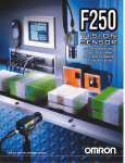
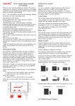
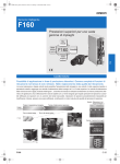
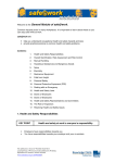
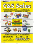
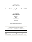
SLAC-SL Solar street light controller
User Manual
LED
Thank you very much for choosing our product. This product manual
provides important information and advices for product installation, use
and troubleshooting. Before using this product, please read carefully and
thoroughly.
Yellow LED 2(M) on
Battery power medium
Yellow LED 3(H) on
Battery power high
Off
Normal operation
Flash
Overload or Short-circuit of load
Red
LED
SLAC-SL is specially designed for solar street light with high cost
performance. It has a number of outstanding features:
Error Description
Indication
The controller adjusts itself automatically to 12V or 24V system voltage.
Sophisticated programmable nightlight function.
Clear readable LED display of the state of charge.
3 stage charging(boost, equalization, float) for flooded battery, 2 stage
charging(boost, float) for sealed battery.
.
Enclosed by aluminum shell and potted by epoxy with high thermal
conductivity. Protection grade reaches IP67.
Loads are not
supplied.
Safety recommendations
Recommend a wire diameter: SLAC - SL10A: 1.5 mm²; SLAC SL20A: 2.5 mm ²,ensure the battery and the controller between the
cable length as short as possible, to prevent controller misjudge battery
voltage.
Cause
Corrective action
Battery is
low(Red LED
on)
Load will reconnect as
soon as battery is
recharged
Over current /
Short circuit of
loads(Red LED
flashing)
Switch off all loads.
Remove short circuit.
Controller will switch on
load automatically after
max 1 minute.
Battery voltage
too high
(>15.5 / 31.0 V)
Check if other sources
overcharge the battery. If
not, controller is damaged
Battery wires or
Check battery wires, fuses
battery fuse
and battery. Remove
damaged, battery
faults.
has high
resistance
Connect the controller by following steps to avoid installation faults.
1. Connect the wire to the controller, then to the battery.
2. Connect the wire to the controller, then to the photovoltaic modules.
3.Connect the wire to the load, then to the controller.
4.Disconnect controller in the reverse order.
Battery is low
after short
time.
Battery has low
capacity(Red
LED on)
Replace the battery.
Battery is not
being charged
during
daytime.
Solar array faulty
or wrong
polarity(Green
LED off)
Check solar array and
wiring. Remove faults.
Nightlight Function
(3)
The controller comes with a sophisticated nightlight function. It controls
the load output at night and is widely programmable. Two modes are
available: Dusk to Dawn and Evening timing.
(1) (2)
Starting up the controller:
Self Test
Light on
As soon as the controller is supplied with power either from the battery or
the solar array, it starts a self test routine. Then the display changes to
normal operation.
Light off
Light on
System Voltage
The controller recognizes day and night based on the solar array open
circuit voltage (Factory setting is 5.0V for 12V system, 10.0V for 24V
system). In Programming Main Menu 3 this day/night threshold can be
modified according to the requirements of the local conditions and the
solar array used.
SLAC-SL Controller has five LEDs. One green LED is for charge
display, three yellow LEDs are for the state of charge display, and one
red LED is for the status of load display.
Normal operation Description
Green
LED
Yellow
Function
On
Normal charge during daytime
Slow flash
Float charge
Fast flash
Equalization charge
Off
Controller connected to battery, night
detected.
Yellow LED 1(L) on
Battery power low
Light off
The mode can be selected in Programming Main Menu 1. If Evening
timing mode is selected. Programming Menu 2 allows choosing the
Evening timing hours.
LED Status and Display
Status
Evening timing
Hours after dusk
The controller adjusts itself automatically to 12V or 24 V system
voltages. As soon as the voltage at the time of start-up exceeds 20.0V,
the controller assumes a 24V system. If the battery voltage is not
within the normal operation range at start-up, a status display according
to the section ERROR DESCRIPTION occurs.
LED
Dust to Dawn
To find the right value, we recommend measuring the solar array open
circuit voltage at the time when twilight has reached the level when the
controller should switch on/off. This value can then be set according to the
description in the programming section.
Mind that the load output is switched off as soon as the battery has
reached the Low Voltage Disconnect threshold, the Low Voltage
Disconnect had priority above the nightlight function.
Both state changes require several minutes of continuous transition values
before making the change. These restrictions avoid false transitions due to
dark storm clouds or lightning.
1
You can enter the programming mode with 2 seconds push on the button.
The programming menu structure is described on the follow page. Mind
that once you have entered the programming menu you can exit it at the
last item only. Exit with a short push < 1 second. All programming
settings are stored in a non-volatile memory and remain stored even if the
controller was disconnected from the battery.
Rated battery charging current
Programming your Solar Controller
Float charge
The button switch has three push modes:
1)Short push Shorter than 1 seconds
2)Long push 2 to 8 seconds
3)Lock out push 8 seconds or longer
Deep discharge protection,
Cut-off voltage
Reconnect level
Under voltage protection
Overvoltage protection
Max. charge current
Max. load current
10A
20A
14.5V / 29V
(25 °C)
14.8V/29.6V
(25 °C)
13.8V / 27.6V
(25 °C)
11V – 12 V/
22V – 24 V
12.8V/25.6V
10.8V/21.6V
15.5V/31.0 V
20A
20A
Max. panel voltage
Temperature compensation
Grounding
14.5V / 29V
(25 °C)
14.8V/29.6V
(25 °C)
13.8V / 27.6V
(25 °C)
11V – 12 V/
22V – 24 V
12.8V/25.6V
10.8V/21.6V
15.5V/31.0 V
10A
10A
4mA-5mA(12V)
6mA-8mA(24V)
50V
-4mV/Cell*K
Positive grounding
Battery type*
Evening hours
Ambient temperature
Dimensions
Wire Length/size
Ambient temperature
IP grade
Max. altitude
Weight
Lead acid (GEL, AGM, flooded)
0 – 12 h
-40°C-+60°C
50mm*56.6mm*20mm
150mm/2.5m²
-40°C-+60°C
IP67
4000m
125g
Main charge
Equalization voltage
By pushing the button for 8 sec in normal operation mode the
programming lock-out is activated to prevent any accidental settings
change. Another 8 sec push releases the lock-out.
Self consumption
With a long push(2s-8s) , you can enter the programming mode. The
programming menu structure is described in the back page. A wide red
arrow means a long push (2s-8s), a narrow dotted line arrow means a
short push (<1sec).
Testing Function
During the daytime the testing function of SLAC-SL can help the user to
verify correct installation or for troubleshooting a system problem. Short
pushing the button will light up the lamp which is connected to the load
terminals. The lights will be on in the day for 3 minutes intervals. Within
3 minutes the lights can be turned off via pushing button. The lights can
turned on repeatedly with pushing button besides when the system is in
LVD (load disconnect/red LED on). In LVD this testing function is not
valid. If pressing the button cause a load disconnects (LVD) the light will
turn off.
*) This version is recommended for flooded batteries only, for sealed
batteries use our different SLAC-SL version
Safety Features
PV terminals
Battery terminals
Load
terminals
Reverse
polarity
24V system: no
12V system: yes
Protected
Protected
Short circuit
Protected
Protected (with fuse
on battery) (3)
Protected
Over current
Protected
Protected
Switches off
with
a delay (3)
Reverse
charge
Protected
No effect
No effect
Over voltage
Max. 55V
Max. 55V
Switches off
with a
delay
Under voltage
No effect
No effect
Switches off
above
15.5/31.0 V
Subject to change without notice.
Version: 20140530
Made in China
www.upnetech.com
When over temperature occurs, the controller will
reduce the charging current. If the temperature of
controller reaches a high level, the load will
automatically be switched off.
(1) Controller can protect itself, but load might be damaged.
(2) We strongly recommend that add a fuse between battery and
controller. The battery may be permanent damaged when short circuit
occurs.
(3) > 200% rated current: Load will be switched off with 3s delay.
Over
temperature
Warning: Two or more error conditions at the same time may cause
damage to the controller. Always remove the present fault condition
before next operation
SLAC-SL Technical Characteristics
Model
SLAC-SL 10A
SLAC-SL 20A
Rated System voltage
12V/24V auto
recognition
12V/24V auto
recognition
2
SLAC-SL Solar Street Light Controller Programming Manual
Normal Operation
Green
LED
Red LED
Yellow
LED2
Yellow
Yellow
LED1
LED3
LED on
LED off
LED Slow
Flash
LED Flash
LED Fast
Flash
Button
Long Push > 2 Second
Enter
Programming
Main Menu
with long push > 2 sec
(Green LED slow flash)
Display Menu(Green
LED Flash)
Short Push < 1 Second
Programming Menu(LED
Fast Flash)
Dusk to Dawn (factory setting)
Evening timing
Main Menu 1
Nightlight off
(Nightlight Mode Selection)
Short push < 1 sec
1h
2h
3h
4h
5h
6h
Main Menu 2
7h
(Evening Timing Hours)
8h
9h
Short push < 1 sec
Exit Programming with short push < 1 sec
0h(factory setting)
10h
11
12h
1.5V/3.0V
2.0V/4.0V
2.5V/5.0V
3.0V/6.0V
3.5V/7.0V
4.0V/8.0V
4.5V/9.0V
5.0V/10.0V(factory setting)
Main Menu 3
(Day / Night Threshold)
5.5V/11.0
6.0V/12.0V
6.5V/13.0V
7.0V/14.0V
7.5V/15.0V