1
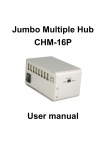
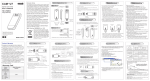
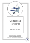
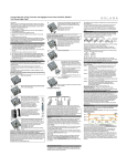
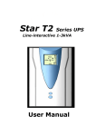
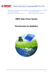
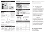
Starting up the controller:
SLAC-I Solar charge controller
User Manual
Self Test
Thank you very much for choosing our product. This product
manual provides important information and advices for product
installation, use and troubleshooting. Before using this product,
please read carefully and thoroughly.
As soon as controller is supplied with power either from the
battery or solar array, it starts a self test routine, this is
indicated first by ruining LCD bars for approx. 0.5 seconds,
then every coded symbol will display for about a second. Then
the display changes to normal operation.
SLAC -I was developed by the latest solar technology standard,
this product has many outstanding feature:
System Voltage
Multi-functional LCD display.
Programmable battery low voltage disconnect with new
ALVD(Adaptive low disconnect).
Selectable battery type – Lead acid battery with liquid
electrolyte, lead-acid battery with solid electrolyte(Gel type or
AGM type). We can adjust the controller by programming
according to battery type.
Sophisticated programmable nightlight function. Can be
programmed to two lighting periods during the night.
The charging characteristics include automatic adaption to the
ambient temperature.
Max .16 mm² connector binding posts. Max safety current can
reach 91A.
Built-in one year date logger.
The controller has a built-in voltage drop compensation which
automatically compensates battery wire voltage drops of up to
250mV.
Complete electronic protection such as over temperature, over
charge, over discharge, over current, short circuit, reverse
polarity.
The controller adjusts itself automatically to 12V or 24V
system voltage, As soon as the voltage as the time of start up
exceeds 20V, the controller assumes a 24V system.
Wiring and grounding:
System conditions are displayed as follows:
The controller is intended for indoor use only or installed in
distribution box. Protect it from direct sunlight and rain. If
installed in distribution box, should avoid the position of
condensed water drip. The controller measures the ambient
temperature to adapt the charging voltage. To ensure the startup of controller, battery voltage should exceed 10V if the
system voltage is 12V, and battery voltage should exceed 20V
if the system voltage is 24V.
The percentage corresponds to the available energy until Low
Voltage Disconnect in relation to a fully charged battery.
If the battery voltage is not within the normal operation
range(approx.12V to 15.5V or approx.24V to 31V) as start
up,a status display according to the section ERROR
DESCRIPTION occurs.
Battery Type
The controller is preset to operate with lead acid batteries with
liquid electrolyte. If you intend to use a VRLA battery(GEL
type) you can adjust the controller in Programming Meau1.The
equalization charge is deactivated then. In case of any doubts,
please consult your dealer.
Display Functions
In normal operation mode the controller displays the state of
charge (available energy) of battery. Any change of the state of
charge (SOC) to a lower status is additionally signaled
acoustically.
As long as the solar array supplies enough voltage to charge the
battery, this is indicated by up moving bars alternately to the
state of charge display.
In normal operation the loads can be switched on and off by
pushing the button. This is indicated in the display:
If the battery voltage is not within the normal operation range
at start-up, a status display according to the section ERROR
DESCRIPTION occurs.
Connect the controller by following steps to avoid installation
faults.
1. Connect the wire to the controller, then to the battery.
2. Connect the wire to the controller, then to the
photovoltaic modules.
3. Connect the wire to the load, then to the controller.
>80%
60-80%
35-60%
10-35%
<10%
Flashes
load off
Follow the reverse procedure when uninstalling to avoid any
damage.
Pushing button within one second, load will manually on or off.
Load manually on
(2)
(1)
Load manually off
Low Voltage Disconnect Function
(3)
1
The controller has 5 different modes to protect the battery from
being deeply discharged. The controller is preset to Mode 1
from the factory, Use Programming Menu 2.to change the
setting( see back page).
Nightlight Function
Mode1: Disconnect at 11.4V/22.8V (at nominal load current)
up to 11.9V/23.8V(at no load current). Normal operation mode
for good battery protection.
Dusk to Dawn and Evening/Morning. The mode can be
selected in Programming Menu 3.
The controller comes with a sophisticated nightlight function. It
controls the load output at night and is widely programmable.
Two modes are available:
Mode2: Disconnect at 11.0V/22.0V (at nominal load current)
up to 11.75V/23.5V(at no load current). Mode with lower
disconnection point. Battery is cycled deeper, this can shorten
battery lifetime.
Mode 3: Disconnect at 11.0V/22.0V to 12.2V/24.4V depending
on load current and previous charging cycles. This adaptive
mode leads to longer lifetime of the battery because it allows
recovery of the battery by full recharge. Maximum battery life.
If Evening/Morning mode is selected, Programming Menu 4
allows choosing the Evening timing behaviors, and
Programming Menu 5 allows choosing the Morning timing
behaviors.
Mode4: Disconnect at 11.5V/23V fixed setting. Appropriate if
bypass loads draw current directly from battery.
Mind that the load output is switched off as soon as the battery
has reached the Low Voltage Disconnect threshold, the Low
Voltage Disconnect had priority above the nightlight function.
Mode5: Disconnect at 11.0V/22.0V fixed setting .Appropriate
if bypass loads draw current directly form battery. Mode with
lower disconnection point. Battery is cycled deeper, this can
shorten battery lifetime.
Mid of night is detected automatically as the middle between
dusk and dawn, no real time setting is required. It may take
some days until the controller has “learnt” midnight. This
method can cause some inaccuracy but avoids any clock
readjustment. The controller’s Mid of night can be different
from the real time midnight depending on your location.
Safety Features
PV terminals
Reverse
polarity
Battery
terminals
Protected
24V system: no
(buzzer alarm
12V system: yes
warning)
Load terminals
The controller recognizes day and night based on the solar
array open circuit voltage. In Programming Menu 6 this
day/night threshold can be modified according to the
requirements of the local conditions and the solar array used.
Protected (1)
Protected(3)
Switches off
(with fuse on
immediately(2)
battery)
Short
circuit
Protected (2)
Over
current
Controller will
reduce the
current.
Protected
Switches off
with
a delay (4)
Reverse
charge
Protected
No effect
No effect
Over
voltage
Max. 55V
Max. 55V
Switches off
above
15.5/31.0 V
Under
voltage
No effect
Switches off
load
Switches off.
The two voltage levels before/after the slash are valid for 12V
and 24V systems respectively.
To find the right value, we recommend measuring the solar
array open circuit voltage at the time when twilight has
reached the level when the controller should switch on/off. This
value can then be set according the description in the
programming section.
When over temperature occurs, the controller
Over
will reduce the charging current. If the
temperature temperature of controller reaches a high level,
the load will automatically be switched off.
(1) Controller can protect itself, but load might be damaged.
(2) Short circuit current: >4x—6x nominal current, <400 A.
(3) We strongly recommend that add a fuse between battery and
controller. The battery may be permanent damaged when short
circuit occurs.
(4) > 200% rated current: Load will be switched off with 3s
delay.
Error Description
Error
Warning: Two or more error conditions at the same time may
cause damage to the controller. Always remove the present
fault condition before next operation
Indication
flashes
2
Cause
Corrective
action
Battery is
low
Load will
reconnect as
soon as battery is
recharged.
Over current
/ Short
circuit of
loads
Switch off all
loads. Remove
short circuit.
Controller will
switch on load
the symbols under “Settings menu” are flashing.
automatically
after max 1
minute.
When you exit the configuration menu, the controller displays
the state of charge (available energy) of the battery and the
status of the load.
Controller is
thermally
Cool down the
overloaded controller. Load
and has
will be switched
disconnected on automatically.
the loads.
Battery
voltage too
high
(>15.5 / 31.0
V)
Loads are not
supplied
Mind that once you have entered the configuration menu you
can exit it at the last item only. We therefore recommend that
you first note down your required settings and then do the configuration in one go.
All configuration settings are stored in a non-volatile memory
and remain stored even if the controller was disconnected from
the battery.
Check if other
sources
overcharge the
battery. If not,
controller is
damaged.
If you want to reset the controller to the factory to the factory
settings, choose Programming Menu 9.
SLAC-I Technical Characteristics
Battery wires
or battery
Check battery
fuse damwires, fuses and
aged, battery
battery.
has high
resistance
Battery
power is low
after a short
time.
Battery has
low capacity
Battery
wrong
polarity
Battery is
connected
with
reverse
polarity.
Change polarity.
Solar array
faulty or
wrong
polarity
Check Solar
array and wiring.
Remove faulty.
Permanent
sound
Battery is not
being
No upcharged
moving bars
during
daytime.
Controller
limits solar
current.
flashes
Model
Rated System voltage
Rated System current
Boost charge
Replace the
battery.
Equalization
Float charge
Deep discharge protection,
cut-off voltage
Reconnect level
Overvoltage protection
Max. charge current
Max. load current
Self consumption
Max. Panel/ Battery
voltage
Temperature
compensation
Grounding
Battery type
Dimensions (WxHxD)
Max. wire size
Ambient temperature
IP grade
Altitude
Net weight
Controller is
thermally
Mount controller
Overloaded
at a location with
or solar array
better ventilation
exceeds
or check solar
nominal curarray current.
rent of
controller.
Programming your Solar Controller
The button switch has three push modes:
1)Short push Shorter than 1 seconds
2)Long push 2 to 8 seconds
3)Lock push 8 seconds or longer
SLAC-I 20A/30A/40A/50A/60A
12V/24V auto recognition
20A 30A 40A 50A 60A
14.5V / 29V(25 °C) 2 h
Activation:
battery voltage < 12.3/24.6 V
14.8V/29.6(25 °C) 2 h
Activation:
battery voltage < 12.1/24.2 V
(at least one time every 30 days)
13.8V / 27.6V(25 °C)
11 – 12 V / 22 – 24 V depending
on setting
12.8V/25.6V
15.5V/31.0 V
20A 30A 40A 50A 60A
20A 30A 40A 50A 60A
4mA
55V
-4.5mV/cell*k
Positive grounding
Lead acid (GEL, AGM, flooded)
140mm*96mm*40mm
16 mm²
-40°C-+60°C
IP22
≤4000m
356g
Subject to change without notice.
Version: 20140530
Made in China
www.upnetech.com
By pushing the button for 8 sec in normal operation mode the
programming lock-out is activated to prevent any accidental
settings change. Another 8 sec push releases the lock-out.
With a long push, you can enter the programming mode. The
programming menu structure is described in the back page. A
black wide arrow means a long push (2s-8s), a gray narrow arrow means a short push (<1sec). The dotted lines under “Setting” mean you see the actual selection there. During selection
3
SLAC-I Solar charge controller programming manual
States of Charge
Mail menu
Mail Menu 1
(Battey Type)
Display Menu
Long push >2 Second
Short push <1 Second
Programming
Menu(Flash)
Liquid Electrolyte Battery Type(factory setting)
GEL(VRLA) Battery Type
Mail Menu 2
(Low Voltage Disconnect)
Low Voltage Disconnect Current
Compensated 11.4V-11.9V
Low Voltage Disconnect Current
Compensated 11.0V-11.75V
Low Voltage Disconnect Current
Compensated/Adaptive 11.0V-12.2V
Low Voltage Disconnect 11.5V
Low Voltage Disconnect 11.0V
Mail Menu 3
(Nightlight Function)
Nightlight Function Off(factory setting)
Nightlight Function Dusk to Dawn
Nightlight Function Evening /Morning
Mail Menu 4
(Nightlight Fuction
Evening Hours)
Nightlight Fuction Evening Off(factory setting)
Nightlight Fuction Evening 1HR
Nightlight Fuction Evening 1HRS
Nightlight Fuction Evening 3HRS
Nightlight Fuction Evening 4HRS
Nightlight Fuction Evening 5HRS
Nightlight Fuction Evening To 4HRS
Before Mid Of Night
Nightlight Fuction Evening To 3HRS
Before Mid Of Night
Nightlight Fuction Evening To 2HRS
Before Mid Of Night
Nightlight Fuction Evening To 1HRS
Before Mid Of Night
Nightlight Fuction Evening To Mid Of Night
Mail Menu 5
(Nightlight Fuction
Morning Hours)
Nightlight Fuction Morning Off(factory setting)
Nightlight Fuction Morning 1HR
Nightlight Fuction Morning 2HRS
Nightlight Fuction Morning 3HRS
Nightlight Fuction Morning 4HRS
Nightlight Fuction Morning 5HRS
Nightlight Function Morning From 2HRS
After Mid of Night
Nightlight Function Morning From 3HRS
After Mid of Night
Nightlight Function Morning From 4HRS
After Mid of Night
Nightlight Function Morning From 5HRS
After Mid of Night
Nightlight Function Morning From 6HRS
After Mid of Night
Mail Menu 6
(Day /Night Threshold)
Day /Night Threshold
1.0V/2.0V Solar Voltage
Day /Night Threshold
1.63V/3.1V Solar Voltage
Day /Night Threshold
2.1V/4.2V Solar Voltage
Day /Night Threshold
2.7V/5.4V Solar Voltage
Day /Night Threshold
3.2V/6.5V Solar Voltage
Day /Night Threshold
3.6V/7.8V Solar Voltage
Day /Night Threshold
4.4V/8.08V Solar Voltage
Day /Night Threshold 4.9V/9.8V
Solar Voltage(factory setting )
Day /Night Threshold 5.5V/11.0V
Solar Voltage
Day /Night Threshold
6.0V/12.1V Solar Voltage
Day /Night Threshold
6.6V/13.2V Solar Voltage
Day /Night Threshold
7.2V/14.3V Solar Voltage
Day /Night Threshold
7.7V/15.4V Solar Voltage
Mail Menu 7
(Buzzer)
Buzzer on(factory setting)
Buzzer off
Mail Menu 8
(Interface Excess)
USB Interface Excess
Energy&Current date
USB Interface Excess
Energy&Datalogger
USB Interface Bidirectional No
Excess Energy(factory setting)
Mail Menu 9
(Keep Settings or Reset)
Keep individual settings
Reset to factory preset