1
page 1 of 75
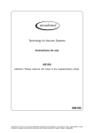
Technology for Vacuum Systems
Instructions for use
MZ 2C EX
MD 4C EX
MV 10C EX
MZ 2C EX + AK + EK
MZ 2C EX + IK + EK
MD 4C EX + AK + EK
MV 10C EX + AK + EK
Chemistry diaphragm pumps
with
ATEX conformity
Documents are only to be used and distributed completely and unchanged. It is strictly the users´ responsibility to check carefully
the validity of this document with respect to his product. manual-no.: 999128 / 29/04/2014
page 2 of 75
Dear customer,
Your VACUUBRAND diaphragm pump shall support you at your work for a long time without any trouble
and with full load output. Thanks to our large practical experience we attained much information how you
could add to an efficient application and to personal safety. Please read these instructions for use prior
to the initial start-up of your pump.
VACUUBRAND diaphragm pumps are the result of many years of experience in construction and practical operation of these pumps combined with the latest results in material and manufacturing technology.
Our quality maxim is the ”zero fault principle”:
Every delivered diaphragm pump is tested extensively including an endurance run of 14 hours. Due to
this endurance run, also faults, which occur rarely, are reported an can be corrected. Every single diaphragm pump is tested on achievement of the specification after the endurance run.
Every VACUUBRAND pump leaving our factory achieves the specification. We feel obliged to
this high quality standard.
We are aware that the vacuum pump should not draw a part of the real work and we hope to contribute
with our products to an effective and trouble-free realisation of your work.
Yours
VACUUBRAND GMBH + CO KG
After sales service: Contact your local dealer or call +49 9342 808-5500.
Attention: This manual is not available in all languages of the
EU. The user must not operate the device if he does not understand this manual. In this case a technically correct translation
of the complete manual has to be available. The manual must
be completely read and understood before operation of the device and all required measures must be applied.
Trademark index:
VACUU•LAN® (US-Reg.No 3,704,401), VACUU•BUS®, VACUU•CONTROLTM, chemistry-HYBRIDTM,
Peltronic®, TURBO•MODETM, VARIO® (US-Reg.No 3,833,788), VARIO-SPTM, VACUUBRAND® (USReg.No 3,733,388) and also the shown company logos are trademarks of VACUUBRAND GMBH + CO
KG in Germany and/or other countries.
Documents are only to be used and distributed completely and unchanged. It is strictly the users´ responsibility to check carefully
the validity of this document with respect to his product. manual-no.: 999128 / 29/04/2014
page 3 of 75
Documents are only to be used and distributed completely and unchanged. It is strictly the users´ responsibility to check carefully
the validity of this document with respect to his product. manual-no.: 999128 / 29/04/2014
page 4 of 75
Documents are only to be used and distributed completely and unchanged. It is strictly the users´ responsibility to check carefully
the validity of this document with respect to his product. manual-no.: 999128 / 29/04/2014
page 5 of 75
Contents
Safety information!......................................................................................................6
General information.............................................................................................................................6
Intended use........................................................................................................................................6
Setting up and installing the equipment..............................................................................................6
Ambient conditions............................................................................................................................10
Operating conditions.........................................................................................................................10
Safety during operation.....................................................................................................................12
Maintenance and repair.....................................................................................................................13
Notes regarding devices with ATEX conformity.....................................................14
Technical data............................................................................................................16
Wetted parts.....................................................................................................................................18
Pump parts.......................................................................................................................................18
Use and operation.....................................................................................................23
Installing in a vacuum system...........................................................................................................23
During operation................................................................................................................................28
Shutdown..........................................................................................................................................30
Troubleshooting........................................................................................................31
Replacing diaphragms and valves..........................................................................32
Inspecting the overpressure safety valve ..............................................................51
Notes on return to the factory..................................................................................53
Health and safety clearance form............................................................................54
EC Declaration of Conformity of the Machinery ........................................................71
➨ DANGER indicates a hazardous situation which, if not avoided, will result in death or serious injury.
☞ WARNING indicates a hazardous situation which, if not avoided, could
result in death or serious injury.
• CAUTION indicates a hazardous situation which, if not avoided, could
result in minor or moderate injury.
NOTICE
NOTICE is used to address practices not related to personal injury.
Caution! Hot surface!
Isolate equipment from mains before removing the cover.
Documents are only to be used and distributed completely and unchanged. It is strictly the users´ responsibility to check carefully
the validity of this document with respect to his product. manual-no.: 999128 / 29/04/2014
page 6 of 75
Safety information!
General information
NOTICE
☞ Read and comply with this manual before installing or operating the equipment.
☞ Transport the pump at the provided handle.
Remove all packing material, remove the product from its packing-box, remove the
protective covers from the inlet and outlet ports and keep, inspect the equipment.
If the equipment is damaged, notify the supplier and the carrier in writing within three
days; state the item number of the product together with the order number and the
supplier’s invoice number. Retain all packing material for inspection.
Do not use the equipment if it is damaged.
If the equipment is not used immediately, replace the protective covers. Store the
equipment in suitable conditions.
Intended use
☞ Use the equipment for the intended use only according to the ATEX conformity, e.
g. for pumping gas atmosphere without aerosol in a range form 0.1 to 1000 mbar
and a maximum inlet pressure (dynamic pressure) and outlet pressure of 1100
mbar (absolute).
☞ The pump and all system parts must not be used on humans or animals.
☞ Prevent any part of the human body from coming into contact with vacuum.
☞ Ensure that the individual components are only connected, combined and operated according to their design and as indicated in the instructions for use.
☞Comply with notes on correct vacuum and electrical connections, see section
”Use and operation”.
The pumps are marked with ”X” (according to EN 13463-1), i. e. restrictions of the
operation conditions:
• The pumps are designated for a low degree of mechanical stress and have to be
installed in a way so that they can not be damaged from outside.
Pumping units have to be installed protected against shocks from the outside and
against glass splinters in the event of breaking (implosion).
• The pumps are designated for an ambient and gas inlet temperature during operation of +10 to +40°C. Never exceed these ambient and gas inlet temperatures.
NOTICE
Use the equipment for the intended use only, i.e. for generation of vacuum in vessels designed for that purpose.
Setting up and installing the equipment
NOTICE
Before system start-up of the pump or the complete system the user has to evaluate
in its entirety the explosion risks and takes adequate measures in application of the
principle of risk assessment.
The evaluation and the measures have to be laid down in an explosion protection
document before system start-up.
The pump/system must not be operated until operation without danger in explosive
atmosphere is ensured. Provide suitable control, protection and warning systems
even in the event of failure.
Documents are only to be used and distributed completely and unchanged. It is strictly the users´ responsibility to check carefully
the validity of this document with respect to his product. manual-no.: 999128 / 29/04/2014
page 7 of 75
The inner (pumped media) and outer part of the pump have to be evaluated
separately because of their different conformity (see also section ”Technical
data” and ”Notes regarding devices with ATEX conformity”).
The pumps are not suitable for pumping dust and have no approval for operation
below ground.
The pumps are not suitable for pumping self inflammable substances, for substances which are inflammable without air and explosive substances.
☞ Electrical and vacuum components might require a separate approval.
☞ Include the components in the recurrent tests of tightness for pressure vessels, in
the case of hits and beats an intermediate leak test is required.
☞ Due to the high compression ratio of the pumps, pressure at the outlet port might
be generated being higher than the max. permitted pressure compatible with the
mechanical stability of the system.
☞ Always provide a free and pressureless exhaust pipeline.
☞Do not permit any uncontrolled pressurizing (e.g. make sure that the exhaust
pipeline cannot become blocked). If there is an exhaust isolation valve, make sure
that you cannot operate the equipment with the valve closed. Risk of bursting!
• Secure coolant hoses at the hose nozzles (e.g. with hose clip) to prevent their
accidental slipping.
• Comply with maximum permissible pressures at inlet and outlet and pressure
differences, see section ”Technical data”. Do not operate the pump with overpressure at the inlet.
• Attention: Flexible elements tend to shrink when evacuated.
NOTICE
Provide a firm level platform for the equipment and check that the system to be
evacuated is mechanically stable and that all fittings are secure. Ensure a stable position of the pump without any mechanical contact except of the pump feet. Comply
with all applicable safety regulations.
Pumping units (pumps with vapour condenser) have to be installed protected
against hits from outside and protected against splinters (against implosion).
Adopt suitable measures prior to the first use.
Obey all relevant requirements (regulations and guidelines) and adopt suitable safety measures.
☞ Pay attention to the max. permitted ambient temperature and make sure
ventilation is adequate especially if pump is installed in a housing or if
ambient temperature is elevated, install an external automatic ventilation
system if necessary.
If pumping hot process gases make sure that the maximum permitted gas inlet
temperature is not exceeded.
☞If the equipment is brought from cold environment into a room for operation,
allow the equipment to warm up (pay attention to water condensation on cold
surfaces).
☞ The work clothing of the user must not lead to electrostatic discharge which may
ignite the explosive atmosphere.
Documents are only to be used and distributed completely and unchanged. It is strictly the users´ responsibility to check carefully
the validity of this document with respect to his product. manual-no.: 999128 / 29/04/2014
page 8 of 75
Inlet
+ Connection lines at the pump inlet have to be performed conductive grounded
and gas tight (designation of the pump connections see figures).
+ The diameter of the inlet pipeline should be at the least as large as the diameter
of the pump connection pipelines.
+ Obey max. inlet pressure (see ”Technical data”).
+ If there is a risk of ignition of gases or gas mixtures before or behind the pump the
user has to provide suitable safety devices against incoming of flames according
to EN 12874. The user must ensure the suitability concerning gas flow, chemical
resistance and safeness against clogging prior to use.
Outlet
+ Connection lines at the pump outlet (small flange) have to be performed conductive grounded and gas tight (designation of the pump connections see figures).
+ The diameter of the inlet pipeline should be at the least as large as the diameter
of the pump connection pipelines.
+ Obey max. inlet pressure (see ”Technical data”).
Due to the high compression ratio of the pumps, pressure at the outlet port might
be generated being higher than the max. permitted pressure compatible with the
mechanical stability of the system.
+ Obey maximum permitted pressures and pressure differences, see section ”Technical data”. Do not operate the pump with overpressure at the inlet.
+ Do not permit any uncontrolled pressurizing (e. g. make sure that the exhaust
pipeline cannot become blocked). If you have an exhaust-isolation valve, make
sure that you cannot operate the equipment with the valve closed. Risk of bursting!
+Ensure that the system design does not allow the exhaust pipeline to become
blocked. Lead away exhaust gas or condensate at the outlet of the pump and the
overpressure safety valve under consideration of all applicable safety measures.
Avoid backflow of gases or condensate definitely.
+ Ensure that the system design does not allow the coolant outlet pipeline to become blocked.
+ Escaped and/or intentional or unintentional released inflammable gases or vapours which may lead to danger of explosion have to be lead away safely or lead
to an appropriate place. If not possible enclose the gasses, vapours or mist safely
or dispose in an other way. In case of mixtures or different gases the measures
must consider the highest risk.
+ If there is a risk of ignition of gases or gas mixtures before or behind the pump the
user has to provide suitable safety devices against incoming of flames according
to EN 12874. The user must ensure the suitability concerning gas flow, chemical
resistance and safeness against clogging prior to use.
Check the overpressure safety valve at the outlet regularly.
+ Attention: If the exhaust pipeline is blocked the pumped gases may escape into
the environment through the overpressure safety valve. If necessary take appropriate measures.
If pumping dangerous gases install a second completely independent exhaust
pipeline instead of the overpressure safety valve. If necessary assemble a hose
nozzle instead of the overpressure safety valve to lead away the gases through
a second exhaust pipeline. Attention: Never combine the exhaust pipelines, i. e.
provide a sperate line for each exhaust.
Documents are only to be used and distributed completely and unchanged. It is strictly the users´ responsibility to check carefully
the validity of this document with respect to his product. manual-no.: 999128 / 29/04/2014
page 9 of 75
Inert gas purge
+ The user must take suitable precautions to prevent any formation of explosive
mixtures in the expansion chamber using inert gas to purge the housing. Otherwise in case of a diaphragm crack, mechanically generated sparks, hot surfaces
or static electricity may ignite these mixtures.
+Inert gas connection lines (inlet and outlet) have to be performed conductive
grounded and gas tight (designation of the pump connections see figures).
+ Connect the inert gas connections at the crankcase not serial but parallel.
+ We recommend an inert gas purge of ≥ 1 l per minute.
+ Provide an external pressure limitation to a pressure of 1.1 bar absolute if inert
gas is connected to the pump or at an air admittance valve. The inert gas has
to be dry and pure. It could be recommendable to provide an appropriate control
system to supervise the inert gas flow which switches off the pump in case of
failure (e. g. absence of inert gas) if necessary.
+To control the faultless function of the diaphragm it could be recommendable
install a gas specific detector at the outlet of the inert gas purge. A signal from
the detector indicates a diaphragm crack. Switch off the pump immediately and
check diaphragms.
+ It is possible to leave out the inert gas purge if the surrounding of the pump is
zone 2 or not an explosive atmosphere.
+ Without inert gas purge the pump outer part has the specification II 3G IIB T4 X.
Gas ballast
+ Use only inert gas for gas ballast.
+ We recommend the use of gas ballast when pumping condensable media.
+ Gas ballast connection lines (inlet and outlet) have to be performed conductive
grounded and gas tight (designation of the pump connections see figures).
+ Connect the inert gas connections at the gas ballast and the crankcase not serial
but parallel.
+ Provide an external pressure limitation to a pressure of 1.1 bar absolute if inert
gas is connected to the pump or at an air admittance valve. The inert gas has
to be dry and pure. It could be recommendable to provide an appropriate control
system to supervise the inert gas flow which switches off the pump in case of
failure (e. g. absence of inert gas) if necessary.
Pumping at high inlet pressure may lead to overpressure at the gas ballast valve.
+ Pumped gases or condensate might be pushed out in case the valve is open.
☞ The inert gas lines have to be chemical resistent due to possible backflow.
Electrical connection
+ Electrical connection of the pump must be performed only by a suitable trained
and supervised personnel.
+ The motor cable for pumps in 230V version contains wires colour coded as follows: green or green and yellow: earth; blue or white: neutral; brown or black:
live.
+ Provide a fuse for the mains cable (L and N) according to the current draw of the
motor, see ”Technical data”.
+ The earth connection of the device (potential equalization) has to be performed
only using the green or green/yellow earth connection wire. Connect the earth
connection wire of the device to the earth connection of the power supply line and
the potential equalization point of the environment of the device.
+ When using pumps with two motors absolutely connect both motors as described
above. Ensure that always both motors are running.
Documents are only to be used and distributed completely and unchanged. It is strictly the users´ responsibility to check carefully
the validity of this document with respect to his product. manual-no.: 999128 / 29/04/2014
page 10 of 75
Attention: Never use the antistatic connection at the housing of the device to
connect the device to ground, use only the green or green and yellow connection
wire of the motor. Use the antistatic connection at the housing only to perform an
antistatic connection of other non-electronic devices and components, e. g. inlet
and outlet vacuum hoses or something similar. Never lead away short-circuit currents using this connection. External electric devices have to be connected at the
potential equalization point of the environment separately and independent of this
device.
+ Equipment must be connected only to a suitable fused and protected electrical
supply and a suitable earth point by suitable trained personnel. Failure to connect
the motor to ground may result in deadly electrical shock.
+Check that mains voltage and current conform with the equipment (see rating
plate).
+ Obey notes regarding the motor in section ”Instructions manual: Explosion
proof motors”, see below.
The motor is protected by a thermal cutout with manual reset combined with an
overcurrent protection.
+ Avoid reliable high heat supply (e. g. due to hot process gases). Maximum permitted gas and ambient temperature se ”Technical data”.
+ Make sure ventilation is adequate especially if pump is installed in a housing or if
ambient temperature is elevated, install an external automatic ventilation system
if necessary.
+ Ensure that in case of pumps with two motors both motors are switched on at
the same time, if not possible switch on the motor of the pump at the outlet first.
Ambient conditions
To the best of our knowledge the equipment is in compliance with the requirements
of the applicable EC-directives and harmonized standards (see ”Declaration of conformity”) with regard to design, type and model, especially directive EN 61010-1.
This directive gives in detail conditions, under which the equipment can be operated
safely (see also IP degree of protection).
Adopt suitable measures in case of differences, e. g. using the equipment outdoors,
installation in altitudes of more than 1000 m above mean sea level, conductive pollution or dewiness.
Pay attention to the permissible maximum ambient and gas inlet temperatures
(see ”Technical data”).
Operating conditions
The pumps have a conformity according to their specification to be installed in areas
and to pump out of areas which contain under normal operation conditions occasionally a potential explosive atmosphere as a mixture of air with inflammable gases or
vapours (category 2). Class of ignition and temperature see ”Technical data”.
The specification for category 2 for the outer part of the pump is only valid when purging the crankcase with inert gas. Without inert gas purging the
pump has the specification II 3G IIB T4 X for the outer part.
Ensure that the materials of the wetted parts are compatible with the pumped substances, see section ”Technical data”.
Documents are only to be used and distributed completely and unchanged. It is strictly the users´ responsibility to check carefully
the validity of this document with respect to his product. manual-no.: 999128 / 29/04/2014
page 11 of 75
+ Adopt suitable measures to prevent the release of dangerous, explosive, corrosive or polluting fluids.
+ If pumping different substances, it is recommended to purge the pump with air
or inert gas prior to changing the pumped media in order to pump out residues
and to avoid reactions of the pumped substances with each other and with the
pump materials.
Take into consideration interactions and chemical reactions of the pumped
media. Ensure that the materials of the wetted parts are compatible with the
pumped substances, see section ”Technical data”.
+The valves and the diaphragms are wear parts. Replace the diaphragms and
valves at the latest at 90% of the typical lifetime or immediately at higher noise
level. The typical lifetime of a diaphragm is 15000 operation hours when pumping
non-corrosive or non-condensable gases, if necessary provide an operation time
counter.
+ Check the overpressure safety valve between the pump stages (only pumps with
four cylinders) regularly and replace at the latest at 90% of the typical lifetime
(typical lifetime: 15000 operation hours).
+ Take adequate precautions to protect people from the effects of dangerous substances (chemicals, thermal decomposition products of fluoroelastomers), wear
appropriate safety-clothing and safety glasses.
+ Obey applicable regulations when disposing of chemicals. Take into consideration that chemicals may be polluted.
+ Adopt suitable measures to prevent contamination of the pumped substances or
the environment.
Electronic equipment is never 100% fail-safe. This may lead to an indefinite status of
the equipment. Provide protective measures against malfunction and failure.
+ Operating the pump, stand still of the pump or operating the air admittance valve
must not lead to a critical dangerous situation under any circumstances.
Ensure that in case of failure the pump and the vacuum system always will turn into
a safe status.
+ In case of leaks in the manifold or diaphragm cracks pumped substances might
be released into the environment or into the pump housing. To reduce the risk of
leaks, ask for a diaphragm pump with additional safety diaphragm.
+ Obey especially notes on operation and use and maintenance.
+ Failure of the pump (e. g. by power failure) or connected components, parts of
the supply (e. g. coolant) or change of parameters (e. g. increase of pressure
in the coolant system) must not lead to a critical dangerous situation under any
circumstances.
Documents are only to be used and distributed completely and unchanged. It is strictly the users´ responsibility to check carefully
the validity of this document with respect to his product. manual-no.: 999128 / 29/04/2014
page 12 of 75
Safety during operation
➨ Adopt suitable measures to prevent the release of dangerous, toxic, explosive,
corrosive, noxious or polluting fluids, vapours and gases. In case install an appropriate collecting and disposal system and take protective action for pump and
environment.
➨ Prevent any part of the human body from coming into contact with vacuum.
➨ Potentially explosive mixtures at the outlet of the pump have to be drained appropriately, sucked off or diluted with inert gas to non-explosive mixtures.
☞ Pay attention to the symbol ”hot surfaces” on the equipment. Adopt suitable
measures to prevent any danger arising from the formation of hot surfaces or
electric sparks. Provide a suitable protection against contact if necessary.
☞ Always provide free and pressureless exhaust pipelines.
+Ensure that the coolant outlet pipeline is always free and that it cannot get
blocked.
Check liquid level in both catchpots regularly and drain condensate in time.
☞ Pumping at high inlet pressure may lead to overpressure at the gas ballast
valve. Pumped gases or condensate might be pushed out in case the valve is
open. If an inert gas supply is connected, ensure that the inlet pipeline is not contaminated.
• Comply with applicable regulations when disposing of chemicals. Take into consideration that chemicals may be polluted.
Take adequate precautions to protect people from the effects of dangerous substances (chemicals, thermal decomposition products of fluoroelastomers), wear
appropriate safety-clothing and safety glasses.
Use only genuine spare parts and accessories.
+ Otherwise safety and performance of the equipment as well as the electromagnetic compatibility of the equipment might be reduced.
+ If not using genuine spare parts the ATEX conformity becomes invalid.
Do not start the pump if the pressure difference between inlet and outlet port exceeds 1.1 bar at maximum.
Prevent the backpressure of gases and the backflow of condensates.
Never suck liquids or dust into the pump.
Ensure that in case of failure the pump and the vacuum system always will turn into
a safe status.
Provide appropriate protective measures (i.e. precautions which allow for the requirements of the respective application) even for the case of failure and malfunction.
Failure of the pump (e.g. due to power failure) or of connected components, parts
of the supply or change of parameters must not lead to a critical dangerous situation under any circumstances. In case of diaphragm cracks or leaks in the manifold
pumped substances might be released into the environment or into the pump housing or motor. Comply especially with notes on operation and use and maintenance.
• Due to the residual leak rate of the equipment, there might be an exchange of
gas, albeit extremely slight, between the environment and the vacuum system.
Adopt suitable measures to prevent contamination of the pumped substances or
the environment.
Documents are only to be used and distributed completely and unchanged. It is strictly the users´ responsibility to check carefully
the validity of this document with respect to his product. manual-no.: 999128 / 29/04/2014
page 13 of 75
Maintenance and repair
Wear parts have to be replaced regularly. In normal use, the lifetime of the diaphragms and valves is typically 15,000 operating hours. Bearings have a typical durability of 40000 h.
• The motor capacitors have to be replaced after 200000 start/stop cycles at the
latest. If an overaged motor capacitor fails it might get hot and even melt and may
cause a flame to form which could be dangerous for persons and equipment
in the vicinity. The capacitors have to be replaced only at the factory.
Use only genuine spare parts and accessories.
+ Otherwise safety and performance of the equipment as well as the electromagnetic compatibility of the equipment might be reduced.
+ If not using genuine spare parts the ATEX conformity becomes invalid.
Ensure that maintenance is done only by suitable trained and supervised technicians.
➨ Isolate equipment from mains and wait two minutes before starting maintenance to allow the capacitors to discharge.
• Before starting maintenance vent the pump, isolate the pump and other components from the vacuum system. Allow sufficient cooling of the pump. Drain condensate, if applicable.
☞ Ensure that the pump cannot be operated accidentally. Never operate the
pump if covers or other parts of the pump are disassembled. Never operate
a defective or damaged pump.
☞ Attention: The pump might be contaminated with process chemicals which have
been pumped during operation. Ensure that the pump is decontaminated before
maintenance and take adequate precautions to protect people from the effects of
dangerous substances if contamination has occurred.
+ Take adequate precautions to protect people from the effects of dangerous substances (chemicals, thermal decomposition products of fluoroelastomers), wear
appropriate safety-clothing and safety glasses.
+ To avoid danger due to electrostatic ignition wipe the device or parts of the device only with a humid cloth.
In order to comply with law (occupational, health and safety regulations, safety at
work law and regulations for environmental protection) vacuum pumps, components
and measuring instruments returned to the manufacturer can be repaired only when
certain procedures (see section ”Notes on return to the factory”) are followed.
Documents are only to be used and distributed completely and unchanged. It is strictly the users´ responsibility to check carefully
the validity of this document with respect to his product. manual-no.: 999128 / 29/04/2014
page 14 of 75
Notes regarding devices with ATEX conformity
This information sheet does not replace the instructions for use!
In directive 89/391/EWG the European Union has defined requirements for safety at work, which later
have been detailed for explosive atmospheres in the directive 1999/92/EG.
The requirements to equipment for operation in explosive atmospheres have been defined in the directive 94/9/EG (also known as ATEX 100a or ATEX 95). In 1996 this directive was implemented into German law (11. Geräteschutzverordnung).
Concerning technology these directives only state general requirements. Technical details and test procedures are „recommended“ in European standards (e.g. for equipment with ATEX conformity: EN 1127,
E50014ff, EN 60079, EN 13463ff.).
Since July 1st 2003 equipment intended for use in potentially explosive atmospheres shall only be sold
if the equipment is in accordance with directive 94/9/EG (ATEX). This applies only to new equipment.
The repair of equipment sold prior to July 1st, 2003 is not affected. Pumps of prior design (pumps with
Ex-approved motor only) must not be brought to the market anymore.
Requirements to user and manufacturer of equipment according to ATEX:
The user of a system according to ATEX has to analyse the overall explosion risks according to directive 1999/92/EC and has to take adequate measures by means of a risk assessment. The evaluation
and validation of measures has to be documented in an explosion protection document, specifying
among other things the areas classified as potentially explosive (see below). The inner part of the pump
(pumped gases) and the environment of the pump (outer explosion protection) have to be evaluated
separately. Often the requirements will be different.
The responsibility for the classification of areas with potentially explosive atmospheres into
zones and for the specification of requirements to the equipment (category of equipment, class
of ignition, temperature class etc.) is accountable strictly to the operator of the system.
The equipment used has to comply with these requirements. VACUUBRAND does not advise
customers concerning requirements to the equipment under the specific aspects of the customers applications.
Equipment with ATEX-conformity is to be used by appropriately instructed personnel only.
ATEX marking, intended use:
The marking of the equipment corresponding with the standards (see above) gives the areas in which
the equipment may be used according to its intended use.
Technical data, safety notes and intended use:
See instructions for use!
The equipment must only be used if the instructions for use are read, fully understood and
obeyed.
Clean, check and maintain equipment regularly.
Do never operate a defective equipment.
Documents are only to be used and distributed completely and unchanged. It is strictly the users´ responsibility to check carefully
the validity of this document with respect to his product. manual-no.: 999128 / 29/04/2014
page 15 of 75
Electrical connection:
VACUUBRAND diaphragm pumps with ATEX-conformity are equipped with a 230 V / 50 Hz singlephase motor and are protected by a thermal cutout with manual reset combined with an overcurrent
protection.
See instructions for use concerning notes on electrical connection
Where applicable the motors can be connected directly to an appropriate power supply by suitably
trained and authorised personnel (electrician). It is the responsibility of the user to meet the requirements of explosion protection in the power supply and connection area.
Vacuum and outlet connections:
See instructions for use: Make sure that all mechanical connections
are always gas tight and electrically conducting.
The exhaust pipeline must be designed in a way that it cannot become blocked.
If the exhaust pipeline becomes blocked, the overpressure safety device at the pump releases potentially dangerous gases into the environment. Take appropriate safety measures (see instructions for
use).
Evaluate the risk of explosion for the release of pumped gases at the outlet of the pump.
Use and connection of inert gas supply:
For external ATEX equipment category 2G (e.g. for use in Ex-zone 1) the crank case of the pump has to
be flushed with inert gas (e.g. nitrogen). A flow of approx. 1 l/min (at atmospheric pressure) is sufficient.
If necessary the flow should be monitored using a flow meter. Without inert gas purge the pump has
external equipment category 3G. This means the pump has to be used in this case only in a surrounding
with Ex - zone 2 (or no Ex-zone).
It is recommended to install a gas detector (specific to the pumped gas) at the outlet of the inert gas tubing. The maximum permitted overpressure at the inert gas outlet is 0.1 bar (Check the flow rate through
the gas detector!). A positive signal from the detector indicates a diaphragm failure. In this event switch
off the pump immediately and check the pump.
In the case of pumping condensable vapours, use gas ballast. Connect inert gas with maximum
overpressure of 0.1 bar to the gas ballast inlet (see instructions for use).
Inlet of air into the gas ballast must never lead to formation of an explosive mixture inside the
pump or at the outlet of the pump!
Documents are only to be used and distributed completely and unchanged. It is strictly the users´ responsibility to check carefully
the validity of this document with respect to his product. manual-no.: 999128 / 29/04/2014
page 16 of 75
Technical data
MZ 2C EX
MZ 2C EX
+ AK + EK
MZ 2C EX
+ IK + EK
Type
ATEX approval
Inner part (pumped gases)
Outer part
Surrounding of the pump with inert gas purge
Surrounding of the pump without inert gas purge
Motor
MD 4C EX MV 10C EX
MD 4C EX MV 10C EX
+ AK + EK + AK + EK
II 2G IIC T3 X
II 2G IIB T4 X
II 3G IIB T4 X
see motor rating plate
Max. pumping speed* according to
ISO 21360
m3/h
1.9
3.7
8.1
Ultimate vacuum* (absolute) without
gas ballast
mbar
12
3
2
Ultimate vacuum* (absolute) with
gas ballast
mbar
18
10
10
Max. permitted pressure at the inlet
and the outlet (absolute)
bar
1.1
Max. permitted pressure difference
between inlet and outlet
bar
1.1
Max. permitted pressure at inert gas
connection (absolute)
bar
1.1
Max. permitted ambient temperature
during operation
°C
+10 to +40
Max. permitted ambient temperature
during storage
°C
-10 to +60
Permitted gas inlet temperature
°C
+10 to +40
Max. surface temperature of the
pump (outer part)
°C
110
Max. permitted atmospheric moisture
during operation
(no condensation)
%
30 to 85
Degree of protection of the pump IEC 529
Pump
Pump + AK + EK / Pump + IK + EK
Nominal current draw
A
Maximum start-up current /
Start-up duration
Max. permitted range of voltage supply / frequency
Integral leak rate
*
**
IP 54**
IP 52**
IP 54**
IP 54**
IP 54**
IP 54**
1.2
2
2x2
5.5 A /
125 ms
10.2 A /
125 ms
2 x 10.2 A /
125 ms
230V ± 10% / 50 Hz
mbar*l/s
0.1
Technical data according to EN 61010-1 and EN 1012-2 recommendation. The pump achieves its ultimate pumping speed and ultimate vacuum only at operating
temperature (after approx. 15 min.).
Only when positioning the pump horizontal.
We reserve the right for technical modifications without prior notice!
Documents are only to be used and distributed completely and unchanged. It is strictly the users´ responsibility to check carefully
the validity of this document with respect to his product. manual-no.: 999128 / 29/04/2014
page 17 of 75
Type
Motor power
kW
No-load speed
min-1
A-weighted emission sound
pressure level***
(uncertainty KpA: 3 dB(A))
dB(A)
Inlet
Pump
Pump + IK + EK
MZ 2C EX
MZ 2C EX +
AK + EK
MZ 2C EX +
IK + EK
MD 4C EX
MD 4C EX +
AK + EK
MV 10C EX
MV 10C EX +
AK + EK
0.15
0.25
2 x 0.25
1500
50
53
53
KF 16
hose nozzle
DN 13 mm
KF 25
-
KF 25
-
Outlet
Pump
Pump + AK + EK / Pump + IK + EK
KF 16
hose nozzle 10 mm
Gas ballast connection
hose nozzle 10 mm
Inert gas purge connection
hose nozzle 8 mm
Recommended flow of inert gas
Overall dimensions L x B x H,
approx.
Pump
Pump + AK + EK
Pump + IK + EK
Mass, approx.
Pump
Pump + AK + EK
Pump + IK + EK
l/min
mm
mm
kg
kg
≥1
340 x 290 x 250 440 x 265 x 305
357 x 308 x 470 600 x 365 x 420
357 x 308 x 470
21.6
25.4
on request
29.3
37.4
-
560 x 430 x 410
on request
63.2
on request
-
*** Measurement according to EN ISO 2151:2004 and EN ISO 3744:1995 at 230V/50Hz and ultimate vacuum with exhaust tube
at outlet.
We reserve the right for technical modifications without prior notice!
Documents are only to be used and distributed completely and unchanged. It is strictly the users´ responsibility to check carefully
the validity of this document with respect to his product. manual-no.: 999128 / 29/04/2014
page 18 of 75
Wetted parts
Components
Wetted parts
Inlet
stainless steel*
Outlet
Pump
Pump + AK + EK
stainless steel**
PBT
Hoses
PTFE, antistatic
Fittings
ETFE / stainless steel*
Housing cover insert
PTFE, carbon reinforced
Head cover
ETFE, carbon reinforced
O-ring in head cover
FPM
Diaphragm clamping disc
ETFE, carbon reinforced
Valve
FFKM or PTFE
Diaphragm
PTFE
Overpressure safety relief device
stainless steel***, PTFE, carbon reinforced,
FFKM
Separator cover plate
PTFE, carbon reinforced
Catchpot, collecting flask,
vapour condenser
borsilicate glass
* stainless steel 1.4404
** stainless steel 1.4541
***stainless steel 1.4404 and 1.4310
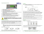
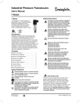
Pump parts
Position
Component
Position
Component
1
inlet (vacuum connection)
12
exhaust waste vapour condenser
2
outlet (gas!)
13
3
on/off switch (0: off, 1: on)
coolant inlet
(hose nozzle 6 mm)
4
rating plate
14
coolant outlet
(hose nozzle 6 mm)
5
handle
15
catchpot
6
gas ballast connection
(only inert gas)
16
cover plate
7
inlet inert gas purge
17
collecting flask
8
outlet inert gas purge
18
immission condenser
9
overpressure valve
10
antistatic connection
11
mains cable
We reserve the right for technical modifications without prior notice!
Documents are only to be used and distributed completely and unchanged. It is strictly the users´ responsibility to check carefully
the validity of this document with respect to his product. manual-no.: 999128 / 29/04/2014
page 19 of 75
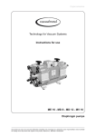
MZ 2C EX
5
3
1
8
6
2
9
10
11
4
7
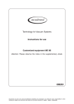
MD 4C EX
5
6
3
4
10
8
11
1
9
7
2
Documents are only to be used and distributed completely and unchanged. It is strictly the users´ responsibility to check carefully
the validity of this document with respect to his product. manual-no.: 999128 / 29/04/2014
page 20 of 75
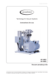
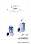
MV 10C EX
5
3
5
6
3
4
11
(2x !)
1
7
8
2
10
9
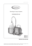
MZ 2C EX + AK + EK
14
7
2
16
12
1
13
8
5
15
Attention: Further designation of the pump components see figure MZ 2C EX
Documents are only to be used and distributed completely and unchanged. It is strictly the users´ responsibility to check carefully
the validity of this document with respect to his product. manual-no.: 999128 / 29/04/2014
page 21 of 75
MZ 2C EX + IK + EK
14
7
16
14
1
2
13
12
18
13
8
5
15
Attention: Further designation of the pump components see figure MZ 2C EX
MZ 2C EX + AK + EK / MZ 2C EX + IK + EK (rear side)
9
3
Attention: Further designation of the pump components see figure MZ 2C EX
Documents are only to be used and distributed completely and unchanged. It is strictly the users´ responsibility to check carefully
the validity of this document with respect to his product. manual-no.: 999128 / 29/04/2014
page 22 of 75
MD 4C EX + AK + EK
14
2
1
12
13
15
17
Attention: Further designation of the pump components see figure MD 4C EX
MV 10C EX + AK + EK
14
2
13
12
1
15
17
Attention: Further designation of the pump components see figure MV 10C EX
Documents are only to be used and distributed completely and unchanged. It is strictly the users´ responsibility to check carefully
the validity of this document with respect to his product. manual-no.: 999128 / 29/04/2014
page 23 of 75
Use and operation
Installing in a vacuum system
• All connection lines at the pump (e. g. inlet, outlet, gas ballast connection, inert
gas connection) have to be performed conductive grounded.
• Connect pump and all connected components to ground.
• Avoid contact of the pump with rusty metal parts, e. g. by positioning the pump
with sufficient distance to surrounding parts.
• The pump is designated for a low degree of mechanical stress. Protect the pump
from damage and beats. In case of damage switch off the pump immediately,
check leak rate if necessary.
• Connection lines at the pump inlet have to be gas tight. Particles and dust must
not be aspirated, the user has to provide appropriate filters if necessary. The user
must ensure their suitability concerning gas flow, chemical resistance and safeness against clogging prior to use.
• Connect an exhaust line gas tight at the pump outlet if necessary. Always dispose
of exhaust gases appropriately (e.g. into a fume hood). If there is risk of release of
dangerous or polluting fluids, install an appropriate system to catch and dispose
of those fluids.
• Reduce the transmission of vibration and prevent mechanical load due to rigid pipelines. Insert elastic hoses or flexible elements as couplings between the
pump and rigid pipes. Attention: Flexible elements tend to shrink when evacuated.
• Use of a suitable valve to isolate the pump from the vacuum system is recommended to allow the pump to warm up before pumping condensable vapours or
to clean the pump before it is switched off.
• The gas outlet must never be blocked. The exhaust line has always to be free
(pressureless) to ensure an unimpeded discharge of gas.
• Especially if the gas ballast valve is open, a power failure may cause accidental
ventilation of the pump. In case this constitutes a potential source of danger, take
appropriate safety measures.
• Make sure ventilation is adequate especially if the pump is installed in a housing
or if the ambient temperature is elevated. Provide external ventilation if necessary. Keep a distance of minimum 20 cm between fan and ambient parts.
NOTICE
Avoid throttling losses by using connecting pipes with large diameter and by keeping
them as short as possible.
In case of perturbing exhaust noise connect an exhaust hose. Install outlet pipelines
always falling to avoid backflow of condensate towards the pump.
When assembling, ensure vacuum-tightness. After assembly, check the whole system for leaks. Secure hose connections at the pump appropriately against accidental
detaching.
NOTICE
Attach the pipelines of the coolant circuit to the respective hose nozzles (hose nozzles 6-8 mm, see image) at the vapour condenser. Check hose connections prior to
starting operation of the cooling system.
Secure coolant hoses at the hose nozzles (e.g. with hose clip) to prevent their accidental slipping.
Documents are only to be used and distributed completely and unchanged. It is strictly the users´ responsibility to check carefully
the validity of this document with respect to his product. manual-no.: 999128 / 29/04/2014
page 24 of 75
• The gas outlet must not be blocked. The exhaust pipeline has always to be free
and pressureless to enable an unhindered discharge of gases.
• If necessary connect the exhaust to a suitable treatment plant to prevent the discharge of dangerous gases and vapours to the surrounding atmosphere.
• Attention: Install hoses of the cooling system in a way to avoid flow / dropping of
condensed water onto the pumping unit (especially cables and electronic parts).
• Ensure that the coolant outlet pipeline is always free and that it cannot get
blocked.
• Install an optional coolant valve always in the supply line of the vapour condenser
only.
Connection of the mains cable
+ Electrical connection of the pump must be performed only by a suitable trained
and supervised personnel.
+ The motor cable for pumps in 230V version contains wires colour coded as follows: green or green and yellow: earth; blue or white: neutral (N); brown or black:
live (L).
+ Provide a fuse for the mains cable (L and N) according to the current draw of the
motor, see ”Technical data”.
+ The earth connection of the device (potential equalization) has to be performed
only using the green or green/yellow earth connection wire. Connect the earth
connection wire of the device to the earth connection of the power supply line and
the potential equalization point of the environment of the device.
Attention: Never use the antistatic connection at the housing of the device to
connect the device to ground, use only the green or green and yellow connection
wire of the motor. Use the antistatic connection at the housing only to perform an
antistatic connection of other non-electronic devices and components, e. g. inlet
and outlet vacuum hoses or something similar. Never lead away short-circuit currents using this connection. External electric devices have to be connected at the
potential equalization point of the environment separately and independent of this
device.
+In case of power failure unintentional venting of the system is possible. Adopt
suitable measures if this might lead to a dangerous situation.
Inlet
+ Connection lines at the pump inlet have to be performed conductive grounded
and gas tight (designation of the pump connections see figures).
+ Particles and dust must not be aspirated, the user has to provide appropriate
filters if necessary. The user must ensure the suitability concerning gas flow,
chemical resistance and safeness against clogging prior to use.
+ If there is a danger of deposits in the pump chamber (check inlet and outlet of the
pump) control the pump chamber regularly and clean if necessary.
+ If there is a risk of ignition of gases or gas mixtures before or behind the pump the
user has to provide suitable safety devices against incoming of flames according
to EN 12874. The user must ensure the suitability concerning gas flow, chemical
resistance and safeness against clogging prior to use.
Connection of the inert gas purge
+ Connect the inert gas connections at the gas ballast and the crankcase not serial
but parallel.
+Inert gas connection lines (inlet and outlet) have to be performed conductive
grounded and gas tight (designation of the pump connections see figures).
+ We recommend an inert gas purge of ≥ 1 l per minute.
Documents are only to be used and distributed completely and unchanged. It is strictly the users´ responsibility to check carefully
the validity of this document with respect to his product. manual-no.: 999128 / 29/04/2014
page 25 of 75
+ To control the faultless function of the diaphragm it could be recommendable to
install a gas specific detector at the outlet of the inert gas purge. A signal from
the detector indicates a diaphragm crack. Switch off the pump immediately and
check diaphragms.
+ If the surrounding of the pump is not an explosive atmosphere it is possible to
leave out the inert gas purge.
Connection of the inert gas gas ballast
+ Connect the inert gas connections at the gas ballast and the crankcase not serial
but parallel.
+ Use only inert gas at the gas ballast connection. Therefore replace the blind cap
at the gas ballast connection by the hose nozzle enclosed.
+ Gas ballast connection lines (inlet and outlet) have to be performed conductive
grounded and gas tight (designation of the pump connections see figures).
+ Provide an external pressure limitation to a pressure of 1.1 bar absolute if inert
gas is connected to the pump or at an air admittance valve. The inert gas has to
be dry and pure. Provide an appropriate control system to supervise the inert gas
flow which switches off the pump in case of failure (e. g. absence of inert gas) if
necessary.
Attention: Important notes regarding the use of gas ballast
+ When using air rather than inert gas, risk of significant damage to equipment and/
or facilities, risk of personal injury or even loss of life exists due to the formation
of hazardous and/or explosive mixtures if air and pumped media react inside or
at the outlet of the pump.
Outlet of the pump
+ Always connect an exhaust lines at the pump outlet (small flange or hose nozzle
10 mm). Perform the outlet line conductive grounded and gas tight (designation
of the pump connections see figures). Always connect the exhaust to a suitable
treatment plant (e. g. hood).
+ Potential explosive mixtures at the outlet of the pump have to be drained appropriately, sucked off or diluted with inert gas not explosive mixtures.
+ If there is a danger of deposits in the pump chamber (check inlet and outlet of the
pump) control the pump chamber regularly and clean if necessary.
+ If there is a risk of ignition of gases or gas mixtures before or behind the pump the
user has to provide suitable safety devices against incoming of flames according
to EN 12874. The user must ensure the suitability concerning gas flow, chemical
resistance and safeness against clogging prior to use.
Overpressure safety valve at the outlet of the pump
+ The overpressure safety valve at the outlet prevents reliable high pressures in the
system. Check overpressure safety valve regularly and replace if necessary.
+ Attention: If the exhaust pipeline is blocked the pumped gases may escape into
the environment through the overpressure safety valve. If necessary take appropriate measures.
If pumping dangerous gases install a second completely independent exhaust
pipeline instead of the overpressure safety valve. If necessary assemble a hose
nozzle (thread G 1/4) instead of the overpressure safety valve to lead away the
gases or condensate through a second exhaust pipeline. Attention: Never combine the exhaust pipelines, i. e. provide a separate line for each exhaust.
Attention: Deposits and condensate may lead to increased temperature and
to excess of the max. permitted temperatures! Increased temperatures possibly
may lead to ignition of flammable mixtures inside the pump.
Use inert gas gas ballast if necessary and check pump regularly for deposits.
Install a gas washing bottle, condenser, filter, separator, etc. at the inlet of the
pump if necessary.
Documents are only to be used and distributed completely and unchanged. It is strictly the users´ responsibility to check carefully
the validity of this document with respect to his product. manual-no.: 999128 / 29/04/2014
page 26 of 75
Pumps with two motors
+ Ensure that in case of pumps with two motors both motors are switched on at the
same time, if not possible switch on the motor of the pump at the outlet first.
+ Connect the inert gas connections at the crankcase not serial but parallel.
Attention: Glass parts (flasks and condensers) of pumping units (pumps
with AK (IK) and EK) have no protection against splinters (against implosion) or against leakage in case of mechanical damage or hits from outside.
The user must ensure an appropriate protection against splinters / implosion or leakage prior to the first use.
MZ 2C EX + AK + EK / MZ 2C EX + IK + EK
➨ Assemble catchpot at the inlet and at the outlet using joint
clips (fig.: MZ 2C EX + AK + EK)
catchpot
at the outlet
catchpot
at the inlet
➨ Assemble hose nozzles for cooling water inlet and outlet at
the vapour condenser.
coolant outlet
(hose nozzle 6 mm)
outlet
(gas!; hose nozzle 10 mm)
coolant inlet
(hose nozzle 6 mm)
MD 4C EX + AK + EK / MV 10C EX + AK + EK
➨ Assemble catchpot at the inlet (1) using joint clips.
+ The collecting flask at the outlet (2) is already assembled.
1
2
outlet
(gas!; hose nozzle 10 mm)
➨ Assemble hose nozzles for cooling water inlet and outlet at
the vapour condenser.
coolant outlet
(hose nozzle 6 mm)
coolant inlet
(hose nozzle 6 mm)
Documents are only to be used and distributed completely and unchanged. It is strictly the users´ responsibility to check carefully
the validity of this document with respect to his product. manual-no.: 999128 / 29/04/2014
page 27 of 75
Separation of condensate:
Attention: Due to electrostatics reasons the vapour condenser has no protective layer to avoid separation of condensed water! Risk of bursting!
• Maximum permissible coolant pressure at the vapour condenser: 6 bar (absolute). Backflow always pressureless.
• Comply with the maximum permissible coolant pressures of additional components in the coolant circuit (e.g coolant valve).
• Avoid overpressure in the coolant circuit (e.g. caused by blocked or squeezed
coolant hoses).
• Install an optional coolant valve always in the supply line of the vapour condenser
only.
Permissible range of coolant temperature at the vapour condenser:
-15°C to +20°C
Check hose connections prior to starting operation of the cooling system.
Check coolant hoses regularly during operation.
Do not allow the catchpots to get overfilled. Maximum liquid level approx. 80% to
avoid problems when removing the catchpots.
Check liquid level in both catchpots regularly and drain catchpots in time.
Removing the catchpots:
Catchpot / collecting flask at outlet:
Remove joint clip, remove catchpot and drain condensate.
Catchpot at inlet:
Admit air or inert gas (via pump inlet) to atmospheric pressure. Remove joint clip,
remove catchpot and drain condensate.
- Reassemble drained catchpots.
Important: Comply with regulations when disposing of solvents/condensates. Reuse if possible, purify if contaminated.
For condensable vapours (water vapour, solvents, ...):
+Do not pump vapour before pump has reached its operating temperature and
without inert gas gas ballast.
+ Use inert gas at the gas ballast to avoid the formation of explosive mixtures.
+ With gas ballast ultimate vacuum will be reduced
+ Do not pump vapour before pump has reached its operating temperature
In case of low boiling solvents when the formation of condensate is unlikely, the use
of gas ballast might be unnecessary.
+ Operating the pump without gas ballast increases the solvent recovery rates at
the vapour condenser.
The exhaust waste vapour condenser enables an efficient condensation of the
pumped vapours at the outlet.
+ Next to 100% solvent recovery.
+ Install hoses for cooling water at the inlet and outlet (hose nozzle 6 mm), secure
hose connections against gliding down.
+ Ensure that the system design does not allow the coolant outlet pipeline to become blocked.
Documents are only to be used and distributed completely and unchanged. It is strictly the users´ responsibility to check carefully
the validity of this document with respect to his product. manual-no.: 999128 / 29/04/2014
page 28 of 75
+ Ensure that the system design does not allow the exhaust pipeline to be blocked
(hose nozzle 10 mm), do not permit uncontrolled pressurizing.
+Connect the exhaust to a suitable treatment plant to prevent the discharge of
dangerous gases and vapours to the surrounding atmosphere.
+The pumped gases at the outlet of the pump or at the exhaust waste vapour
condenser have to be drained under consideration of all applicable safety regulations.
The user has to check the possibility of an explosive atmosphere at the outlet of
the pump or the exhaust waste vapour condenser. Therefore for example calculate the solvent partial pressure at the present cooling water temperature at the
exhaust waste vapour condenser and compare with the explosion limits of the
pumped solvent. If there is an explosive mixture, drain the gas at the outlet in
antistatic lines according to the valid explosion protection guidelines.
During operation
• Maximum ambient temperature: 40 °C
• Make sure ventilation is adequate especially if the pump is installed in a housing
or if the ambient temperature is elevated. Install an external automatic ventilation
system if necessary.
• If the pump is installed in altitudes of more than 1000 m above mean sea level
check compatibility with applicable safety requirements, especially IEC 60034
(motor might overheat due to insufficient cooling).
+ If the pump has been exposed to increased ambient temperature (> 40°C)
check the pump for damage and perform a leak test if necessary (integral
leak rate < 0.1 mbar*l/s).
• Potentially explosive mixtures at the outlet of the pump have to be drained appropriately.
• Due to the high compression ratio of the pumps, pressure at the outlet port might
be generated being higher than the max. permitted pressure compatible with the
mechanical stability of the system.
+ Check compatibility with max. permitted pressure at the inlet and the outlet and
max. pressure difference between inlet and outlet ports.
Ensure that the pump outlet is not blocked or restricted.
Do not start pump if pressure difference between inlet and outlet port exceeds
max. 1 bar. Attempts to start pump at higher difference may cause blockade
and damage of the motor. Check compatibility with maximally permitted pressure at inlet and outlet.
Check the pump regularly at the outside for pollution or deposits, clean the pump if
necessary to avoid increase of the operation temperature of the pump.
If pumping different substances purge the pump with inert gas prior to change the
pumped media to pump out residues and to avoid reactions of the pumped substances with each other and the pump material.
Take into considerations interactions and chemical reactions of the pumped media.
Documents are only to be used and distributed completely and unchanged. It is strictly the users´ responsibility to check carefully
the validity of this document with respect to his product. manual-no.: 999128 / 29/04/2014
page 29 of 75
The pump achieves its pumping speed, ultimate total vacuum and vapour pumping
rate only at operating temperature (after approx. 15 minutes).
+ Prevent internal condensation, transfer of liquids or dust. The diaphragm and
valves will be damaged, if liquids are pumped in significant amounts.
+ Let the pump run with gas ballast to reduce condensation of pumped substances
(water vapour, solvents, ....) in the pump.
The motor is protected by a thermal cutout with manual reset combined with an
overcurrent protection.
+ Attention: Only manual reset is possible. Determine cause of switching off and
eliminate. Allow sufficient cooling of the pump prior to switching on again (approx.
5 minutes).
+ Reset of the pump must performed only by a suitably trained technician!
➨ Separate the pump from mains and wait two minutes before opening the terminal
until hot parts have discharged.
Attention: Open the terminal only outside of explosive atmospheres and only by
suitably trained personnel.
➨ Unscrew the terminal cover from the pump motor.
➨ Push the switch inside the terminal.
➨ Screw the terminal cover correctly, screw tightening torque: 23 Nm.
Attention:
Absolutely check the motor capacitor for leaks and capacity if the motor protection has been activated.
Check the complete pump for leaks in the gas line (integral leak rate < 0.1 mbar
l / s)!
terminal cover
(at the pump motor)
motor capacitor
switch for resetting
the motor protection
Documents are only to be used and distributed completely and unchanged. It is strictly the users´ responsibility to check carefully
the validity of this document with respect to his product. manual-no.: 999128 / 29/04/2014
page 30 of 75
Shutdown
NOTICE
Short-term:
Has the pump been exposed to condensate?
Allow the pump to continue to run at atmospheric pressure for a few minutes.
Has the pump been exposed to media which may damage the pump materials or
form deposits?
Check and clean pump heads if necessary.
Long-term:
Take measures as described in section short-term shutdown.
Separate pump from the apparatus.
Close inlet and outlet port (e. g. with transport caps).
Close the gas ballast valve.
Store the pump in dry condition
Documents are only to be used and distributed completely and unchanged. It is strictly the users´ responsibility to check carefully
the validity of this document with respect to his product. manual-no.: 999128 / 29/04/2014
page 31 of 75
Troubleshooting
Never operate a defective pump!
Read and obey the instructions for use!
Fault
Possible cause
Remedy
❑
➨
Mains not plugged in, electrical supply failure?
✔
➨
Pressure in outlet pipeline too ✔
high?
➨
Motor overloaded?
✔
Allow the motor to cool down,
identify cause of failure and
eliminate. Reset the motor
protection and switch on the
pump, see section above.
➨
Centring ring at small flange
✔
connection not correctly positioned or leak in the pipeline
or vacuum system?
Check pump directly - connect vacuum gauge directly
at pump inlet - then check
connection, pipeline and
vacuum system if necessary.
➨
Long, narrow line?
✔
Use lines with larger diameter, length as short as
possible.
➨
Pump has been exposed to
condensate?
✔
Allow pump to run for some
minutes with atmospheric
pressure at the inlet.
➨
Deposits have been formed
inside the pump?
✔
Clean and inspect the pump
heads.
➨
Diaphragms or valves damaged?
✔
Replace diaphragms and/or
valves.
➨
Outgassing substances or
vapour generated in the
process?
✔
Check process parameters.
Loud exhaust noise?
✔
Connect hose or silencer to
pump outlet.
Diaphragm crack or diaphragm clamping disc loose?
✔
Perform maintenance.
➨
Motor bearing defective?
✔
Contact local distributor.
➨
Deposits have been formed
inside the pump?
✔
Clean and inspect pump
heads.
➨
Diaphragms or valves defective?
✔
Replace diaphragms and/or
valves.
➨
Other than above mentioned
causes?
✔
Contact local distributor.
✔
Contact local distributor.
❑
❑
❑
Pump does not start or
stops immediately.
Pump does not achieve
its ultimate vacuum or
usual pumping speed.
➨
Pump too noisy.
Attention: Switch off
pump immediately and
➨
inspect!
Pump seized.
Check power supply and
fuse in the building installation.
Remove blockade in line,
open valve.
Documents are only to be used and distributed completely and unchanged. It is strictly the users´ responsibility to check carefully
the validity of this document with respect to his product. manual-no.: 999128 / 29/04/2014
page 32 of 75
Replacing diaphragms and valves
NOTICE
All bearings are encapsulated and are filled with long-life lubricant and run under
normal operating conditions maintenance free. Replacement of the bearing must be
performed at the latest at 90% of the nominal lifetime of the bearing (nominal lifetime of the bearing: 40000 operation hours, if necessary provide an operation time
counter). If the noise level is enhanced switch off the pump immediately and inspect.
Replacement of the bearing must only performed at the factory. Never operate a
defective pump.
NOTICE
The motor capacitors are wear parts. The motor capacitors have to be replaced after
200000 start/stop cycles at the latest. The capacitors have to be replaced only at the
factory.
NOTICE
The valves and the diaphragms are wear parts. Replace the diaphragms at the latest at 90% of the typical lifetime or immediately at higher noise level. The typical
lifetime of a diaphragm is 15000 operation hours when pumping non-corrosive or
non-condensable gases, if necessary provide an operation time counter.
Pumping condensable media, operation at high temperature, great gas flow or
deposits reduce the lifetime of a diaphragm significantly. Therefore check the diaphragm regularly for faultless condition.
+ Prevent internal condensation, transfer of liquids or dust. The diaphragm and
valves will be damaged, if liquids are pumped in significant amount.
NOTICE
To control the faultless function of the diaphragm install a gas specific detector at the
outlet of the inert gas flush. A signal from the detector indicates a diaphragm crack.
Switch off the pump immediately and check diaphragms.
If the rated ultimate vacuum is no longer achieved, the pump interior, the hose connections, the diaphragms and the valves must be cleaned and the diaphragms and
valves must be checked for cracks or other damage. Replace defective parts immediately.
NOTICE
Inspect the fittings of the pump regularly, the maximum permitted leak rate is 0.1
mbar l / s.
When replacing diaphragms and valves check the overpressure safety valve at the
outlet of the pump.
Remove possible deposits in the crank chamber of the pump when replacing diaphragms and valves.
If the pump is exposed to corrosive gases or gases and vapours which may form deposits (e. g. crystallisation) or deposits due to pumped particles, maintenance should
be carried out frequently (according to the experience of the user).
+ Regular maintenance will improve the lifetime of the pump and also protect both
man and environment.
Before starting maintenance vent the system, isolate the pump and other components from the vacuum system and the electrical supply. Drain condensate if applicable, avoid the release of pollutants. Allow sufficient cooling of the pump. Before
starting maintenance, wait two minutes after isolating the equipment from mains to
allow the capacitors to discharge.
Never operate the pump if covers or other parts of the pump are disassembled. Ensure that the pump cannot be operated accidentally. Never operate a defective or
damaged pump.
Ensure that the maintenance technician is familiar with the safety procedures which
relate to the products processed by the pumping system.
Documents are only to be used and distributed completely and unchanged. It is strictly the users´ responsibility to check carefully
the validity of this document with respect to his product. manual-no.: 999128 / 29/04/2014
page 33 of 75
Attention: The pump might be contaminated with the process chemicals that have
been pumped during operation. Ensure that the pump is decontaminated before
maintenance and take adequate precautions to protect people from the effects of
dangerous substances if contamination has occurred.
+ Wear appropriate safety-clothing when you come in contact with contaminated
components.
NOTICE
+ Please
read section ”Replacing diaphragms and valves” completely before starting maintenance.
Partially the pictures show pumps in other versions. This doesn’t influence replacing diaphragms and valves of the pump.
NOTICE
Attention:
The pump heads of VACUUBRAND ATEX diaphragm pumps are
assembled in two different versions. This is only visible after disassembling the pump heads.
Replacing diaphragms and valves is described for both versions
separately.
NOTICE
If not using genuine spare parts the ATEX conformity becomes invalid.
Attention: Open the pump only outside of explosive atmospheres and only by
suitably trained personnel.
Always replace both diaphragms of a pump head!
Always disassemble and assemble only one pump head before opening the
next pump head. The single parts of a pump head are measured in a way so to
avoid that the diaphragm clamping disc hits the head cover. Never mix parts
of different pump heads or add or leave out washers.
We recommend to replace all diaphragms and valves of a pump at the same
time.
Spare parts
Set of seals (diaphragms, valves, O-rings)
MZ 2C EX / MZ 2C EX + AK + EK / MZ 2C EX + IK + EK�����������������������������������������������������1 x 696837
MD 4C EX / MD 4C EX + AK + EK..........................................................................................2 x 696837
MV 10C EX / MV 10C EX + AK + EK��������������������������������������������������������������������������������������4 x 696837
Sealing bond (PTFE) ...................................................................................................................637514
Valve (one piece)..........................................................................................................................637225
(internal overpressure valve in MD 4C EX, MD 4C EX + AK + EK, MV 10C EX, MV 10C EX + AK + EK)
O-Ring 28 x 2.5.............................................................................................................................635628
at the spherical ground joint of the catchpot at the inlet
Flat seal (overpressure safety valve at the outlet)������������������������������������������������������������������������637081
Spring (overpressure safety valve at the outlet)���������������������������������������������������������������������������637065
Documents are only to be used and distributed completely and unchanged. It is strictly the users´ responsibility to check carefully
the validity of this document with respect to his product. manual-no.: 999128 / 29/04/2014
page 34 of 75
Version 1
Tools required (metric):
-
-
-
-
Phillips screw driver size 2
Open-ended wrench size 10/15/17
Hex key size 5
Face wrench with torque indicator
(fig. VACUUBRAND face wrench cat. no.: 637580)
Cleaning and inspecting the pump heads
➨ Use open-ended wrench to unscrew the inert gas fitting at
the housing cover.
➨ Unscrew the housing plate from the pump.
➨ Unscrew the union nut at the elbow fitting of the pump
head and remove hose.
+ Turn the fittings as little as possible and do not remove the
fittings from the pump head.
Through reassembly a leak may result.
➨ Position the pump on the motor.
Unscrew the locking plate at the inert gas connection and
remove hose.
Documents are only to be used and distributed completely and unchanged. It is strictly the users´ responsibility to check carefully
the validity of this document with respect to his product. manual-no.: 999128 / 29/04/2014
page 35 of 75
➨Use hex key to remove four socket head screws from
pump head and remove upper housing (housing cover
with housing cover insert and head cover).
+ Never remove parts by using a spiky or sharp-edged tool
(e. g. screw driver), we recommend to use a rubber mallet
or compressed air (to be blown carefully into port).
➨Carefully remove head cover from housing cover insert
and check valves. Note position of valves and remove.
+ Replace valves if necessary.
+Use petroleum ether or industrial solvent to remove deposits. Do not inhale.
Replacing the diaphragm
➨ Use a face wrench to remove diaphragm support disc.
➨ Check for washers under clamping disc. Do not mix the
washers from the different heads. Make sure that the original number and thickness of washers is reassembled at
the individual pump head.
➨ Never increase the amount of washers.
Risk of temperature increase!
Risk of explosion!
➨ Remove the intermediate flange with clamping discs, diaphragms and diaphragm support discs from the pump
housing.
Remove the diaphragm support disc of the safety diaphragm and safety diaphragm.
Documents are only to be used and distributed completely and unchanged. It is strictly the users´ responsibility to check carefully
the validity of this document with respect to his product. manual-no.: 999128 / 29/04/2014
page 36 of 75
View of the disassembled pump head parts (fig. MZ 2C EX)
housing
rod
washer
inlet
safety diaphragm
clamping disc
diaphragm support disc
washer
intermediate flange
outlet
overpressure
safety valve
safety diaphragm
work diaphragm
diaphragm support disc
head cover
diaphragm clamping disc
valve
O-ring
housing cover with
housing cover insert
Documents are only to be used and distributed completely and unchanged. It is strictly the users´ responsibility to check carefully
the validity of this document with respect to his product. manual-no.: 999128 / 29/04/2014
page 37 of 75
View of the disassembled pump head parts (fig. MD 4C EX)
internal overpressure
safety valve
distributor
inlet
cover plate
overpressure
safety
valve
outlet
housing
rod
washer
diaphragm support disc
safety diaphragm
safety diaphragm clamping disc
washer
diaphragm support disc
intermediate flange
work diaphragm
diaphragm clamping disc
head cover
O-ring
valve
housing cover insert
housing cover
Documents are only to be used and distributed completely and unchanged. It is strictly the users´ responsibility to check carefully
the validity of this document with respect to his product. manual-no.: 999128 / 29/04/2014
page 38 of 75
View of the disassembled pump head parts (fig. MV 10C EX)
head cover
diaphragm clamping disc
work diaphragm
housing cover
diaphragm support disc
housing cover insert
washer
intermediate flange
safety diaphragm
clamping disc
safety diaphragm
valve
safety diaphragm
support disc
O-ring
washer
housing
rod
inlet
cover plate
distributor cover
distributor
internal overpressure
safety valve
outlet
overpressure
safety valve
Documents are only to be used and distributed completely and unchanged. It is strictly the users´ responsibility to check carefully
the validity of this document with respect to his product. manual-no.: 999128 / 29/04/2014
page 39 of 75
➨Use the metal face wrench to disassemble diaphragm
clamping disc, diaphragm and diaphragm support disc
(use a open-ended wrench to fix the components).
Before reassembling ensure that all parts are clean, dry
and lint free, especially the valve seat. Remove residual
adhesive.
➨ Position new diaphragm between diaphragm clamping
disc with square head screw and diaphragm support disc.
+ Attention: Position diaphragm with white PTFE side to diaphragm clamping disc (to pump chamber).
+ Make sure that the square head screw of the diaphragm
clamping disc is correctly seated in the guide hole of the
diaphragm support disc.
➨ Use a face wrench with torque indicator to assemble diaphragm clamping disc, diaphragm and diaphragm support
disc with safety diaphragm clamping disc (use a openended wrench to fix the components).
+ Make sure that the square head screw of the diaphragm
clamping disc is correctly seated in the guide hole of the
diaphragm support disc.
Optimum torque for the diaphragm support disc: 6 Nm.
+The optimum torque is reached when the pointer in the
handle of the VACUUBRAND face wrench points to position 2 which is the long line between the two shorter lines.
Do not tighten over 6 Nm!
+ Ensure conductance of the connection.
Abb. VACUUBRAND face wrench with torque indicator
position 2: indicator should point here when the optimal torque is reached
position 1: resting position
➨ Position diaphragm clamping disc, diaphragm and diaphragm support disc with safety diaphragm clamping disc
in the intermediate flange from the side which has a deepening as guidance for the diaphragm. Position safety diaphragm and safety diaphragm support disc from the other
side.
+ Attention: Position diaphragm with the light side towards
the pump chamber.
Ensure correct position of the diaphragm support disc (see
also exploded drawing). Assemble the side with the smaller bearing surface towards the diaphragm.
Documents are only to be used and distributed completely and unchanged. It is strictly the users´ responsibility to check carefully
the validity of this document with respect to his product. manual-no.: 999128 / 29/04/2014
page 40 of 75
➨ Use a face wrench with torque indicator to assemble safety diaphragm support disc under the safety diaphragm with
rod.
+ Attention: Absolutely assemble all
washers correct if available (between
safety diaphragm support disc and
rod). Never assemble more washers!
+ Make sure that the square head screw of the diaphragm
clamping disc is correctly seated in the guide hole of the
diaphragm support discs.
Optimum torque for the diaphragm support disc: 6 Nm.
+ The optimum torque is achieved if the pointer in the handle
of the VACUUBRAND face wrench shows to the longer
marking line (see above).
+ Ensure conductance of the connection.
Assembling the pump head
➨ Position pump in a way so that the disassembled pump
head is above, support if necessary.
➨By turning eccentric bushing (front of connecting rod),
bring connecting rod into a position in which diaphragm is
in contact with housing and centred with respect to bore.
Reassemble in reverse order.
➨ Install head cover with O-ring, valves and housing cover
with housing cover insert.
+ Make sure that the valves are correctly seated: Valves at
the outlet with round centred opening under valve, valves
at the inlet with kidney-shaped opening beside valve.
+ Ensure that the diaphragm is positioned centrally so that it
will become clamped uniformly between housing and head
cover.
3
1
2
4
➨ Screw in four socket head screws fixing housing cover
crosswise (e. g. in the sequence 1,2,3,4) first slightly, then
tighten.
+ Do not tighten until head cover is in contact with housing,
torque 12 Nm.
Attention: Ensure that the diaphragm clamping disc
never hits the head cover! In case of loud knocking
switch off the pump immediately.
Inspect pump or replace diaphragms and valves at the
other pump heads analogue.
Documents are only to be used and distributed completely and unchanged. It is strictly the users´ responsibility to check carefully
the validity of this document with respect to his product. manual-no.: 999128 / 29/04/2014
page 41 of 75
➨ Screw housing plate to pump.
Individual performance check of a pump head
➨Measure the pressure at the inlet port of the individual
head: Use a suitable vacuum gauge (e. g. DVR 2, cat.
no.: 682902), make sure that it is correctly calibrated, and
measure the pressure at the inlet port. A vacuum of less
than 120 mbar should be indicated.
+If the reading is higher, recheck the pump chamber and
make sure that the valves and the diaphragms are correctly seated (diaphragms concentric with bore).
Assembling fittings
➨ Position pump on pump feet.
➨ Connect hose to elbow fitting.
➨ Tighten union nuts first by hand and then tighten one full
turn using open ended wrench.
➨ Position the pump on the motor.
Attach hose to the inert gas connection and screw the
locking plate.
➨ Use open-ended wrench to screw the inert gas fitting at
the housing cover.
Documents are only to be used and distributed completely and unchanged. It is strictly the users´ responsibility to check carefully
the validity of this document with respect to his product. manual-no.: 999128 / 29/04/2014
page 42 of 75
Attention: Perform a leak test always after opening the pump by
using an appropriate leak detector (e. g. helium leak detector)!
Ensure that the diaphragm clamping disc never hits the head
cover while pump is running! Noise check!
If the pump does not achieve the ultimate pressure:
+ In case the diaphragms and valves have been replaced, a run-in period of several
hours is required before the pump achieves its ultimate vacuum.
If all pump heads achieve a vacuum below 120 mbar but pump does not achieve the
ultimate total pressure:
Check hose connectors between pump heads and manifolds for leaks. If necessary
recheck pump chamber.
Documents are only to be used and distributed completely and unchanged. It is strictly the users´ responsibility to check carefully
the validity of this document with respect to his product. manual-no.: 999128 / 29/04/2014
page 43 of 75
Version 2
Tools required (metric):
-
-
-
-
-
-
-
Phillips screw driver size 2
Open-ended wrench size 10/15/17
Open-ended wrench size 19, 4.5 mm thick
Torque wrench size 19
Hex key size 5
Diaphragm key SW 66 (cat. no.: 636554)
Open-ended wrench size 19 with torque indicator
Cleaning and inspecting the pump heads
➨ Use open-ended wrench to unscrew the inert gas fitting at
the housing cover.
➨ Unscrew the housing plate from the pump.
➨ Unscrew the union nut at the elbow fitting of the pump
head and remove hose.
+ Turn the fittings as little as possible and do not remove the
fittings from the pump head.
Through reassembly a leak may result.
➨ Position the pump on the motor.
Unscrew the locking plate at the inert gas connection and
remove hose.
Documents are only to be used and distributed completely and unchanged. It is strictly the users´ responsibility to check carefully
the validity of this document with respect to his product. manual-no.: 999128 / 29/04/2014
page 44 of 75
➨Use hex key to remove four socket head screws from
pump head and remove upper housing (housing cover
with housing cover insert and head cover).
+ Never remove parts by using a spiky or sharp-edged tool
(e. g. screw driver), we recommend to use a rubber mallet
or compressed air (to be blown carefully into port).
➨Carefully remove head cover from housing cover insert
and check valves. Note position of valves and remove.
+ Replace valves if necessary.
+Use petroleum ether or industrial solvent to remove deposits. Do not inhale.
Replacing the diaphragm
➨ Remove intermediate flange by hand.
+ Check diaphragm for damage and replace if necessary.
➨ Lift diaphragm carefully sidewise.
+Never use a spiky or sharp-edged tool to lift the diaphragm.
➨ Use the diaphragm key to grip the diaphragm support disc
below the diaphragm.
➨ Unscrew diaphragm support disc with diaphragm and diaphragm clamping disc.
➨ Never increase the amount of washers.
Risk of temperature increase!
Risk of explosion!
➨Remove clamping disc of the safety diaphragm with an
open-ended wrench and remove together with safety diaphragm and support disc.
Documents are only to be used and distributed completely and unchanged. It is strictly the users´ responsibility to check carefully
the validity of this document with respect to his product. manual-no.: 999128 / 29/04/2014
page 45 of 75
View of the disassembled pump head parts (fig. MZ 2C EX)
housing
rod
washer
inlet
diaphragm support disc
safety diaphragm
clamping disc
washer
intermediate flange
outlet
overpressure
safety valve
head
cover
safety diaphragm
work diaphragm
diaphragm support disc
O-ring
valve
housing cover
diaphragm clamping disc
housing cover insert
Documents are only to be used and distributed completely and unchanged. It is strictly the users´ responsibility to check carefully
the validity of this document with respect to his product. manual-no.: 999128 / 29/04/2014
page 46 of 75
View of the disassembled pump head parts (fig. MD 4C EX)
housing
distributor
internal overpressure
safety valve
inlet
overpressure
safety
valve
rod
outlet
washer
diaphragm support disc
safety diaphragm
safety diaphragm clamping disc
washer
diaphragm support disc
intermediate flange
work diaphragm
diaphragm clamping disc
head cover
O-ring
valve
housing cover insert
housing cover
Documents are only to be used and distributed completely and unchanged. It is strictly the users´ responsibility to check carefully
the validity of this document with respect to his product. manual-no.: 999128 / 29/04/2014
page 47 of 75
View of the disassembled pump head parts (fig. MV 10C EX)
head cover
diaphragm clamping disc
housing cover insert
housing cover
work diaphragm
diaphragm support disc
washer
intermediate flange
safety diaphragm
clamping disc
safety diaphragm
valve
diaphragm support disc
housing
O-ring
washer
rod
distributor
inlet
cover plate
internal overpressure
safety valve
distributor cover
outlet
over-pressure
safety valve
Documents are only to be used and distributed completely and unchanged. It is strictly the users´ responsibility to check carefully
the validity of this document with respect to his product. manual-no.: 999128 / 29/04/2014
page 48 of 75
Before reassembling ensure that all parts are clean, dry and
lint free, especially the valve seat.
➨ Position new safety diaphragm between safety diaphragm
clamping disc and safety diaphragm support disc.
☞ Attention: Position diaphragm with pale side towards diaphragm clamping disc.
☞ Make sure that the square head screw of the diaphragm
clamping disc is correctly seated in the guide hole of the
diaphragm support disc.
Use torque wrench w/f 19 to screw safety diaphragm support
disc, safety diaphragm and safety diaphragm clamping disc
to rod.
+ Attention: Absolutely assemble all
washers correctly if available (between
safety diaphragm support disc and
rod). Never assemble more washers!
☞ Make sure that the square head screw of the diaphragm
clamping disc is correctly seated in the guide hole of the
diaphragm support disc.
Optimum torque for the safety diaphragm clamping disc: 6
Nm.
➨ Position new work diaphragm between diaphragm clamping disc with square head screw and diaphragm support
disc.
☞ Attention: Position diaphragm with pale side towards diaphragm clamping disc (to pump chamber).
☞ Make sure that the square head screw of the diaphragm
clamping disc is correctly seated in the guide hole of the
diaphragm support disc.
➨ Lift diaphragm at the side and position carefully together
with diaphragm clamping disc and diaphragm support disc
in the diaphragm key.
☞ Avoid damage of the diaphragm: Do not bend diaphragm
too much.
➨ Position intermediate flange to housing.
➨Screw diaphragm clamping disc, diaphragm, diaphragm
support disc and washers to connecting rod.
➨ Optimum torque for the diaphragm support disc: 6 Nm, it
is recommended to use a torque key. Attach hex key to
diaphragm key (hexagonal bolt 6 mm wide).
Attention: Never use the diaphragm key with any additional tools like tongs or hex keys without torque limitation.
Documents are only to be used and distributed completely and unchanged. It is strictly the users´ responsibility to check carefully
the validity of this document with respect to his product. manual-no.: 999128 / 29/04/2014
page 49 of 75
Assembling the pump head
➨ Position pump in a way so that the disassembled pump
head is above, support if necessary.
➨By turning eccentric bushing (front of connecting rod),
bring connecting rod into a position in which diaphragm is
in contact with housing and centred with respect to bore.
Reassemble in reverse order.
➨ Install head cover with O-ring, valves and housing cover
with housing cover insert.
+ Make sure that the valves are correctly seated: Valves at
the outlet with round centred opening under valve, valves
at the inlet with kidney-shaped opening beside valve.
+ Ensure that the diaphragm is positioned centrally so that it
will become clamped uniformly between housing and head
cover.
3
1
2
4
➨ Screw in four socket head screws fixing housing cover
crosswise (e. g. in the sequence 1,2,3,4) first slightly, then
tighten.
+ Do not tighten until head cover is in contact with housing,
torque 12 Nm.
Attention: Ensure that the diaphragm clamping disc
never hits the head cover! In case of loud knocking
switch off the pump immediately.
Inspect pump or replace diaphragms and valves at the
other pump heads analogue.
➨ Screw housing plate to pump.
Individual performance check of a pump head
➨Measure the pressure at the inlet port of the individual
head: Use a suitable vacuum gauge (e. g. DVR 2, cat.
no.: 682902), make sure that it is correctly calibrated, and
measure the pressure at the inlet port. A vacuum of less
than 120 mbar should be indicated.
+If the reading is higher, recheck the pump chamber and
make sure that the valves and the diaphragms are correctly seated (diaphragms concentric with bore).
Documents are only to be used and distributed completely and unchanged. It is strictly the users´ responsibility to check carefully
the validity of this document with respect to his product. manual-no.: 999128 / 29/04/2014
page 50 of 75
Assembling fittings
➨ Position pump on pump feet.
➨ Connect hose to elbow fitting.
➨ Tighten union nuts first by hand and then tighten one full
turn using open ended wrench.
➨ Position the pump on the motor.
Attach hose to the inert gas connection and screw the
locking plate.
➨ Use open-ended wrench to screw the inert gas fitting at
the housing cover.
Attention: Perform a leak test always after opening the pump by
using an appropriate leak detector (e. g. helium leak detector)!
Ensure that the diaphragm clamping disc never hits the head
cover while pump is running! Noise check!
If the pump does not achieve the ultimate pressure:
+ In case the diaphragms and valves have been replaced, a run-in period of several
hours is required before the pump achieves its ultimate vacuum.
If all pump heads achieve a vacuum below 120 mbar but pump does not achieve the
ultimate total pressure:
Check hose connectors between pump heads and manifolds for leaks. If necessary
recheck pump chamber.
Documents are only to be used and distributed completely and unchanged. It is strictly the users´ responsibility to check carefully
the validity of this document with respect to his product. manual-no.: 999128 / 29/04/2014
page 51 of 75
Inspecting the overpressure safety valve
Inspecting the overpressure safety valve at the outlet:
➨ Unscrew the overpressure safety valve at the outlet of the
pump.
MZ 2C EX
MD 4C EX
MV 10C EX
➨Disassemble the overpressure safety valve and inspect
the parts for faultless condition, replace damaged parts.
➨ Reassemble the valve correctly.
➨ Screw the overpressure safety valve to the outlet of the
pump.
Inspection and replacement of the internal overpressure safety valve at the manifold:
(only MD 4C EX / MD 4C EX + AK + EK)
MD 4C EX
(A)
➨ Use an open-ended wrench (width 17 mm) to unscrew at
the pump heads the union nuts of the tubings which are
connected to the manifold (5x).
Elbow fitting (3x):
➨ Turn the fitting with an open-ended wrench (width 14 mm)
to detach the tubing from the pump head (1/4 of a turn at
maximum).
+ Do not remove the elbow fitting from the pump head.
Straight fitting (2x):
➨ Pull the tubing off the fitting.
➨Unscrew the two countersunk screws (A) at the cover
plate and remove cover plate together with distributor and
tubing.
Documents are only to be used and distributed completely and unchanged. It is strictly the users´ responsibility to check carefully
the validity of this document with respect to his product. manual-no.: 999128 / 29/04/2014
page 52 of 75
➨ Note position of valve and remove.
+ Check valve for damage and replace if necessary. Make
sure that the valve is correctly seated.
➨ Reassemble distributor and cover plate.
Elbow fitting (3x):
➨ Slip the tubing onto the elbow fitting by turning the fitting
with an open-ended wrench (width 15 mm).
Straight fitting (2x):
➨ Slip the tubing onto the fitting.
➨ Tighten union nuts first by hand and then tighten one full
turn using the open ended wrench (width 17 mm).
Inspection and replacement of the internal overpressure safety valve at the manifold
at the outlet:
(only MV 10C EX / MV 10C EX + AK + EK)
(A)
➨ Use an open-ended wrench (width 17 mm) to unscrew at
the pump head the union nut of the tubing which is connected to the outlet.
➨ Turn the fitting with an open-ended wrench (width 14 mm)
to detach the tubing from the fitting (1/4 of a turn at maximum).
+ Do not remove the elbow fitting from the distributor cover.
➨ Unscrew the two countersunk screws (A) at the cover plate
and remove cover plate together with distributor cover.
➨ Note position of valve and remove.
+ Check valve for damage and replace if necessary. Make
sure that the valve is correctly seated.
➨ Reassemble distributor cover and cover plate.
➨ Slip the tubing onto the elbow fitting by turning the fitting
with an open-ended wrench (width 15 mm).
➨ Tighten union nut first by hand and then tighten one full
turn using the open ended wrench (width 17 mm).
Documents are only to be used and distributed completely and unchanged. It is strictly the users´ responsibility to check carefully
the validity of this document with respect to his product. manual-no.: 999128 / 29/04/2014
page 53 of 75
Notes on assembling fittings
The threads of the fittings at the pump heads might be sealed with PTFE bond (width 10 mm or 5 mm,
thickness 0.1 mm).
If the fittings are turned or have been removed, use new PTFE bond when reassembling.
If not using new fittings clean the thread of the fittings from PTFE bond.
Wind the thread of the fitting two times against the direction of turning in (anticlockwise) with PTFE
bond.
Tighten the PTFE bond firmly. Ensure that the PTFE bond ends flush with the fittings. Ensure that the
PTFE bond not covers the openings in the elbow fittings.
Screw in elbow fittings (clockwise) until only half of a thread course is visible. Do not overtighten. Avoid
canting of the thread.
fig. ETFE elbow fitting
(example)
hose attachment
thread / section for PTFE bond
direction of winding the thread with PTFE bond
Seal only the lower half of the thread of the stainless steel fittings with PTFE
bond (width 5 mm), see figure. Sealing the complete thread with PTFE bond
leads to interruption of the conductive connection!
Never seal the hose attachment of metal fittings with PTFE bond.
fig. metal fitting (example)
hose attachment
thread
{
hose attachment
PTFE bond
thread
{
PTFE bond
direction of winding the thread with PTFE bond
Documents are only to be used and distributed completely and unchanged. It is strictly the users´ responsibility to check carefully
the validity of this document with respect to his product. manual-no.: 999128 / 29/04/2014
page 54 of 75
Notes on return to the factory
Repair - return - DAkkS calibration
NOTICE
Safety and health of our staff, laws and regulations regarding the handling of dangerous goods, occupational health and safety regulations and regulations regarding
safe disposal of waste require that for all pumps and other products the “Health and
safety clearance form“ must be sent to our office fully completed and signed before
any equipment is shipped to the authorized service center.
Fax or mail a completed copy of the health and safety clearance form to us in advance. The declaration must arrive before the equipment. Enclose a second completed copy with the product. If the equipment is contaminated, you must notify
the carrier.
No repair / DAkkS calibration is possible unless the correctly completed form
is returned. Inevitably, there will be a delay in processing the equipment if information is missing, or if this procedure is not followed.
If the product has come in contact with chemicals, radioactive substances or other
substances dangerous to health or environment, the product must be decontaminated prior to sending it back to the service center.
- Return the product to us disassembled and cleaned and accompanied by a
certificate verifying decontamination or
- Contact an industrial cleaning and decontamination service directly or
- Authorize us to send the product to an industrial cleaning facility at your expense.
To expedite repair and to reduce costs, please enclose a detailed description of the
problem and the product’s operating conditions with every product returned for repair.
We submit repair quotations only on request and always at the customer’s expense. If an order is placed, the costs incurred for problem diagnosis are offset from
the costs for repair or from the purchase price, if the customer prefers to buy a new
product instead of repairing the defective one.
- If you do not wish a repair on the basis of our quotation, the equipment may
be returned to you disassembled and at your expense.
In many cases, the components must be cleaned in the factory prior to repair.
For cleaning we use an environmentally friendly water based process. Unfortunately
the combined attack of elevated temperature, cleaning agent, ultrasonic treatment
and mechanical stress (from pressurised water) may result in damage to the paint.
Please mark in the health and safety clearance form if you wish a repaint at your
expense just in case such a damage should occur.
We will also replace parts for cosmetic reasons at your request and at your expense.
NOTICE
Before returning the equipment ensure that (if applicable):
- Oil sealed pumps: Oil has been drained and an adequate quantity of fresh oil has
been filled in to protect against corrosion. Dispose according to regulations.
- Equipment has been cleaned and/or decontaminated (inside and outside).
- All inlet and outlet ports have been capped.
- Equipment has been properly packed, (if necessary, please order original packaging materials at your costs), marked appropriately and notify the carrier of any
possible contamination.
- The completed health and safety declaration is enclosed.
We thank you in advance for your understanding the necessity for these measures
that protect our employees, and ensure that your device is protected in shipment.
Scrapping and waste disposal:
Dispose of the equipment and any components removed from it safely in accordance with all local and national safety and environmental requirements. Particular
care must be taken with components and waste oil which have been contaminated
with dangerous substances from your processes. Do not incinerate fluoroelastomer
seals and O-rings.
- You may authorize us to dispose of the equipment at your expense.
Documents are only to be used and distributed completely and unchanged. It is strictly the users´ responsibility to check carefully
the validity of this document with respect to his product. manual-no.: 999128 / 29/04/2014
page 55 of 75
Health and safety clearance form
Devices will not be accepted for any handling before we have received this declaration.
Please read and comply with ”Notes on return to the factory”.
Oil filled pumps: Drain oil prior to shipping absolutely!
1. Device (Model): ................................................................... 2. Serial no.: .........................................
3. Reason for return / malfunction:
..............................................................................................................................................................
4. Has the device been used in a copper process step (e.g., semiconductor production).
☐ yes ☐ no
5. Substances (gases, liquids, solids) in contact with the device / which have been pumped:
..............................................................................................................................................................
..............................................................................................................................................................
..............................................................................................................................................................
..............................................................................................................................................................
6. Prior to return to the factory the device has been decontaminated.
☐ yes ☐ no
Description of the decontamination method and the test / verification procedure:
..............................................................................................................................................................
..............................................................................................................................................................
7. The device is free of hazardous, harmful substances.
☐ yes ☐ no
8. Protective measures required for VACUUBRAND employees:
..............................................................................................................................................................
9. If the paint is damaged, we wish a repaint or a replacement of parts for reason of appearance (repaint
and replacement at customer’s expense). ☐ yes ☐ no
10.Legally binding declaration
We assure for the returned device that all substances, which have been in contact with the device are
listed in section 5 and that the information is complete and that we have not withheld any information. We
declare that all measures - where applicable - have been taken listed in section “Return to the factory”.
By our signature below, we acknowledge that we accept liability for any damage caused by providing incomplete or incorrect information and that we shall indemnify VACUUBRAND from any claims as regards
damages from third parties. We are aware that as expressed in § 823 BGB (Public Law Code of Germany) we are directly liable for injuries or damages suffered by third parties, particularly VACUUBRAND
employees occupied with handling/repairing the product.
Shipping of the device must take place according to regulations.
Name: ....................................................................... Signature: ..............................................................
Job title: .................................................................... Company’s seal:
Date: .......................................................................
Release for repair grant by VACUUBRAND (date / signature):
..............................................................
VACUUBRAND GMBH + CO KG
Tel.: +49 9342 808-5660
Alfred-Zippe-Straße 4
Fax: +49 9342 808-5666
Documents
only to be used and distributed E-Mail:
completely
and unchanged. It is strictly the users´ responsibility to check carefully
97877
Wertheim,are
Germany
[email protected]
the validity of this document with respect to his www.vacuubrand.com
product. manual-no.: 999128 / 29/04/2014
page 56 of 75
„INSTRUCTIONS MANUAL“ for motors with mark „EEX“
Documents are only to be used and distributed completely and unchanged. It is strictly the users´ responsibility to check carefully
the validity of this document with respect to his product. manual-no.: 999128 / 29/04/2014
page 57 of 75
Documents are only to be used and distributed completely and unchanged. It is strictly the users´ responsibility to check carefully
the validity of this document with respect to his product. manual-no.: 999128 / 29/04/2014
page 58 of 75
Documents are only to be used and distributed completely and unchanged. It is strictly the users´ responsibility to check carefully
the validity of this document with respect to his product. manual-no.: 999128 / 29/04/2014
page 59 of 75
Documents are only to be used and distributed completely and unchanged. It is strictly the users´ responsibility to check carefully
the validity of this document with respect to his product. manual-no.: 999128 / 29/04/2014
page 60 of 75
Documents are only to be used and distributed completely and unchanged. It is strictly the users´ responsibility to check carefully
the validity of this document with respect to his product. manual-no.: 999128 / 29/04/2014
page 61 of 75
Certificate for motors with mark „EEX“
Documents are only to be used and distributed completely and unchanged. It is strictly the users´ responsibility to check carefully
the validity of this document with respect to his product. manual-no.: 999128 / 29/04/2014
page 62 of 75
Documents are only to be used and distributed completely and unchanged. It is strictly the users´ responsibility to check carefully
the validity of this document with respect to his product. manual-no.: 999128 / 29/04/2014
page 63 of 75
Documents are only to be used and distributed completely and unchanged. It is strictly the users´ responsibility to check carefully
the validity of this document with respect to his product. manual-no.: 999128 / 29/04/2014
page 64 of 75
„INSTRUCTIONS MANUAL“ for motors with mark „EX“
ELNOR MOTORS NV
INSTRUCTIONS MANUAL: EXPLOSION PROOF MOTORS
INTRODUCTION
An explosion-proof, and in particular a flameproof motor, is one that is inherently safe when
working in potentially explosive atmospheres.
This means that its construction and assembly are designed so that ingress of explosive gases
or dusts is rendered harmless for the environment.
In the event of accidental ignition, provoking an explosion inside the motor housing, the motor
shell and brackets are strong enough to resist the internal pressure created by this explosion.
Moreover, assembly joints and shaft clearance must be long enough and offer minimum play, so
that hot gases or dusts resulting from an explosion will be cooled sufficiently to create no
possibility of an explosion outside the motor.
The outside temperature of the motor enclosure must also be kept well below the flash point of
the gases or dusts present in the hazardous atmosphere, both in normal and abnormal working
conditions.
Finally, it is the manufacturer's concern that components inside the motor should be able to
withstand an occasional explosion without being adversely affected.
The degree of risk is dependant on the constituents of the hazardous atmosphere: even
combustible dust can become explosive when spread in the air in the right proportion.
Therefore, existing risks have been divided into categories, depending on the temperature at
which the gas, dust or vapour mixtures become flammable, and also on their explosive energy.
For each of these, specific safety rules have been evolved on a European level.
Compliance with these rules is verified by an Ex notified body, approved for certification in
accordance with article 9 of the European Community Council directive, no 94/9/CEE of 23
march 1994.
Certification delivered by any of the notified bodies is automatically valid in all CEE countries. It
is recognised by all European adherent countries and also very seriously considered in many
countries overseas, U.S.A. included.
In Belgium, it is the “Institut Scientifique de Service Public”, in short ISSeP, which has been
chosen for its long experience in problems of safety in mining industries.
As explosion proof motors are constructed with special materials and technologies that comply
with the legal regulations concerning potentially explosive atmospheres, a wrong connection or
a minor modification of the motor destroys the compliance with security regulations. The rules
concerning explosion proof apparatus must be observed unconditionally. Note that our motors
are approved for a specific group of hazardous areas and temperature classes.
USE OF Ex d II B / IP6x MOTORS
The user is responsible for the choice of the type of explosion proof motor. He has to take into
account the explosion risks area in which the motor will run (classification of hazardous areas,
temperature class,…).
Before installation, the user has to check if the group and protection class, marked on the motor
label, corresponds with the requested conditions.
INCOMING INSPECTION
Inspect the motor to detect any signs of damage during the transport.
Check that the motor nameplate data complies with your order or specification. In the unlikely
event of a claim, please contact our Sales Office.
12/12/08
INSTRUCTIONS MANUAL
1/5
Documents are only to be used and distributed completely and unchanged. It is strictly the users´ responsibility to check carefully
the validity of this document with respect to his product. manual-no.: 999128 / 29/04/2014
page 65 of 75
ELNOR MOTORS NV
STORAGE
The motor should be stored in a clean, dry and vibrations free environment. . If the motor is to
be stored for a long period of time, the machined surfaces protected with anti-rust coating
should be checked and "touched up" if necessary.
If the motor is fitted with anti-condensation heaters, these should be connected during the
storage period.
MOUNTING AND START UP
Electric data of the motor, valid for the rated power, can be found on the nameplate.
It is the responsibility of the user to ensure that the motor nameplate voltage and frequency are
the same as the mains supply.
Connection to the mains supply should only be executed by a recognised professional,
respecting local demands and regulations.
The user must ensure that the diameter of the cable is adequate for the voltage and current
involved. (See nameplate data of motor)
The connection of the wires must be done as described in the connection diagram that is
delivered with the motor. The connection diagram is usually located inside the cover of the
terminal box. If the motor does not have a terminal box, it is located on the housing or attached
to the cable.
The connection diagram is structured as follows: (see example)
Brown
Blue
Mains supply
Black
Black
Relay control
Yellow / green
The leads can be coloured or numbered. Each line represents one lead.
The given connection diagram is an example only.
The motor must be protected against overloads and short-circuits.
When installing the motor, always connect the earth, using the earthing screw in the terminal
box or on the motor frame. Always check local regulations and demands.
The manufacturer cannot be held responsible for damage due to incorrect installation or use.
Free circulation of fresh air for cooling the motor must be guaranteed
The maximum ambient temperature must not exceed the given value that is indicated on the
nameplate and in the motor certificate.
To guarantee the explosion proof protection, certified explosion proof cable glands with sealing
joints adapted to the cable diameters, must be used.
THE MOTOR WILL LOSE ITS EXPLOSION PROOF CHARACTERISTICS IF THE CABLE AND
GLANDS ARE NOT FITTED CORRECTLY!
12/12/08
INSTRUCTIONS MANUAL
2/5
Documents are only to be used and distributed completely and unchanged. It is strictly the users´ responsibility to check carefully
the validity of this document with respect to his product. manual-no.: 999128 / 29/04/2014
page 66 of 75
ELNOR MOTORS NV
Note: If a spare opening for a cable gland isn't used, only the use of a certified explosion proof
plug retains the explosion proof characteristics.
Particular attention is to be given to the fixing torque of bolts and screws. The motor fixing bolts
are factory mounted with the correct torque and should not be touched.
It may be necessary to open the terminal box for connecting the motor. When re-mounting the
cover, only use the original screws.
IMPORTANT: Firstly tighten all screws by hand before applying the full torque. Then tighten the
screws until the spring ring is flat.
Using a pulley or a coupling device:
Apply only well balanced discs and couplings. Check the alignment after assembling
Take care while mounting of the pulley on the shaft: Hammering on the shaft will damage the
motor bearings. Pulleys should only be mounted with appropriate mounting tools that do not
stress the motor bearings.
Following these recommendations will greatly increase the expected motor bearing life.
Safety regulations in respect of guarding couplings and belts from being accidentally touched
must be applied.
Use of a frequency converter:
In areas with an explosion risk, the use of the motor over a frequency converter is limited.
The frequency converter must in such case be placed outside the explosion-endangered area. If
the frequency converter needs to be placed inside the explosion-endangered area, the
additional requirements for such an installation must be respected.
It should be verified that the functioning of the motor is not influenced in a way that the
requirements for Ex-environments are no longer satisfied.
MOTOR PROTECTION
If the motor is equipped with an automatic reset thermal protection, the motor will in case of
thermal cutout restart automatically and without warning after a certain cooling period. Contact
the manufacturer if you need more information on the type of protection that is used.
If the motor is supplied with a thermal protection that is brought out separately, the user must
connect the protection in a way that the motor is switched off when the protector switches.
MAINTENANCE
The maintenance of the motor can be limited to periodic inspection of the ventilation circuit, to
keep it conveniently unobstructed, and to the replacement of the bearings; this period depends
on the working conditions and ambient. Re-greasing is not necessary, the ball bearing are
lubricated for life. In the presence of dust, the motor needs to be cleaned on a regular basis.
In the case of DC motors with brushes in continuous contact with the slip rings, the slip rings,
the brushes and the brush-holders should be periodically cleaned by vacuum cleaning.
REPAIR
The explosion proof motor must not be opened while the motor is energised.
Qualified persons only may do repair or service of the motor. If the customer himself carries out
the operation, he must observe the valid standards. If a repairer treats the motor, he has to
hand a certificate of conformity to the user.
The manufacturer is not responsible for motors that are modified or opened without his written
agreement.
12/12/08
INSTRUCTIONS MANUAL
3/5
Documents are only to be used and distributed completely and unchanged. It is strictly the users´ responsibility to check carefully
the validity of this document with respect to his product. manual-no.: 999128 / 29/04/2014
page 67 of 75
ELNOR MOTORS NV
SPARE PARTS
For each order of spare parts, the type and number of the motor must be given; these data are
indicated on the nameplate.
MARKING OF ATEX CERTIFIED MOTORS
The motor marking contains the following information with regards to the Ex protection:
CE xxxx
Ex II 2 G
ISSeP 08 ATEX yyy X
Ex d II B T4
CE
xxxx
Ex
II
2
G
CE marking
ID of notified body responsible for surveillance
Community mark for explosion proof equipment
Field of application (Group II includes all fields of application except mining)
Category of protection: For group II: 3 (Normal), 2 (High level) or 1 (Very high level)
Gas hazardous locations (G, D)
ISSeP
08
ATEX
yyy
X
Ex d
II
B
T4
21
IP
Notified body
Year of emission (2007, 2008, 2009, …)
ATEX directive
Consecutive number of the year
Special conditions for safe use (if any)
Type of protection (flameproof for use in an explosive gas atmosphere)
Group of equipment
Gas group (the classification of gases into groups is described in the standard EN600079)
Temperature classification (T3 to T6, see table below)
Category of protection: 22 (Normal), 21 (High level) or 20 (Very high level)
Ingress protection
Temperature Class (Group II)
Maximum surface temperature
T3
200°C
T4
135°C
T5
100°C
T6
85°C
The maximum surface temperature of equipment must always be lower than the ignition
temperature of the gas in the hazardous area.
SAFETY CONSIDERATIONS
During normal use, the motor may get hot. (See above table of surface temperatures.)
Precautions may be needed to avoid the risk of burns.
The motor shaft turns at the speed that is indicated on the nameplate, and is potentially
dangerous. Precautions may be needed to ensure safe use.
In general, the relevant safety prescriptions for machines must be respected.
12/12/08
INSTRUCTIONS MANUAL
4/5
Documents are only to be used and distributed completely and unchanged. It is strictly the users´ responsibility to check carefully
the validity of this document with respect to his product. manual-no.: 999128 / 29/04/2014
page 68 of 75
ELNOR MOTORS NV
EUROPEAN DIRECTIVES:
Description
Directive for explosive atmospheres (ATEX)
Electromagnetic Compatability (EMC)
Low voltage directive (LVD)
Machinery directive
EXPLOSION PROOF
MANUFACTURING:
STANDARDS
Directive reference
94/9/EC
2004/108/EG
2006/95/EC
98/37/EC
TAKEN
INTO
CONSIDERATION
DURING
Electrical apparatus for explosive gas atmospheres – part 0: general EN 60079-0
requirements
Electrical apparatus for explosive gas atmospheres – Part 1: Flameproof EN 60079-1
enclosure ‘d’
MANUFACTURER INFORMATION:
ELNOR MOTORS NV
De Costerstraat 45
B-3150 HAACHT
BELGIUM
Telephone:
Fax:
E-mail
Internet
+32 16 60 13 94
+32 16 60 64 40
[email protected]
http://www.elnor.be
This document has been made with the greatest care and is correct at the time of printing. It is
meant as a general guideline and it is not meant to be complete. Always check with relevant
regulations and guidelines.
12/12/08
INSTRUCTIONS MANUAL
5/5
Documents are only to be used and distributed completely and unchanged. It is strictly the users´ responsibility to check carefully
the validity of this document with respect to his product. manual-no.: 999128 / 29/04/2014
page 69 of 75
Certificate for motors with mark „EX“
Documents are only to be used and distributed completely and unchanged. It is strictly the users´ responsibility to check carefully
the validity of this document with respect to his product. manual-no.: 999128 / 29/04/2014
page 70 of 75
Documents are only to be used and distributed completely and unchanged. It is strictly the users´ responsibility to check carefully
the validity of this document with respect to his product. manual-no.: 999128 / 29/04/2014
page 71 of 75
Documents are only to be used and distributed completely and unchanged. It is strictly the users´ responsibility to check carefully
the validity of this document with respect to his product. manual-no.: 999128 / 29/04/2014
page 72 of 75
Documents are only to be used and distributed completely and unchanged. It is strictly the users´ responsibility to check carefully
the validity of this document with respect to his product. manual-no.: 999128 / 29/04/2014
page 73 of 75
Documents are only to be used and distributed completely and unchanged. It is strictly the users´ responsibility to check carefully
the validity of this document with respect to his product. manual-no.: 999128 / 29/04/2014
page 74 of 75
EG-Konformitätserklärung für Maschinen
EC Declaration of Conformity of the Machinery
Déclaration CE de conformité des machines
Hersteller / Manufacturer / Fabricant:
VACUUBRAND GMBH + CO KG · Alfred-Zippe-Str. 4 · 97877 Wertheim · Germany
Hiermit erklärt der Hersteller, dass die Maschine konform ist mit den Bestimmungen der Richtlinie
2006/42/EG. Hereby the manufacturer declares that the machinery is in conformity with the directive
2006/42/EC.
Par la présente, le fabricant déclare, que la machine est conforme à directive 2006/42/CE.
Membranvakuumpumpe / Diaphragm vacuum pump / Pompe à membrane:
Typ / Type / Type: MZ 2C EX / MZ 2C EX + AK + EK / MZ 2C + IK + EK / MD 4C EX / MD 4C EX + AK + EK
/ MV 10C EX / MV 10C EX + AK + EK
Artikelnummer / Order number / Numéro d‘article: 696920 / 696921 / 2614231 / 696930 / 696931 /
696945 / 2614250
Seriennummer / Serial number / Numéro de série: Siehe Typenschild / See rating plate / Voir plaque
signalétique
Die Maschine ist konform mit weiteren Richtlinien / The machinery is in conformity with other directives
/ La machine est conforme à d’autres directives:
2006/95/EG, 2004/108/EG, 94/9/EG, 2011/65/EU
Angewandte harmonisierte Normen / Harmonized standards applied / Normes harmonisées utilisées:
DIN EN 12100:2004, DIN EN 61010-1:2010 (Ed. 3), DIN EN 1012-2:2011, DIN EN 61326-1:2006,
DIN EN 1127-1:2011, DIN EN 13463-1:2009, DIN EN 50581:2013,
Motor / motor / moteur: „EEX“: EN 50014:1997 + A1/A2:1999, EN 50018:2000, EN 50281-1-1:1998;
Motor / motor / moteur: „EX“: EN 60079-0:2006, EN 60079-1:2007
Bevollmächtigter für die Zusammenstellung der technischen Unterlagen / Person authorised to compile
the technical file / Personne autorisée à constituer le dossier technique:
Dr. J. Dirscherl · VACUUBRAND GMBH + CO KG · Alfred-Zippe-Str. 4 · 97877 Wertheim · Germany
Wertheim, 12.02.2014
............................
Ort, Datum / place, date / lieu, date
............................
(Dr. F. Gitmans)
Geschäftsführer / Managing director / Gérant
ppa.
.................................
(Dr. J. Dirscherl)
Technischer Leiter / Technical Director / Directeur technique
VACUUBRAND GMBH + CO KG
Alfred-Zippe-Str. 4 · 97877 Wertheim
T +49 9342 808-0 · F +49 9342 808-5555
[email protected]
www.vacuubrand.com
Documents are only to be used and distributed completely and unchanged. It is strictly the users´ responsibility to check carefully
the validity of this document with respect to his product. manual-no.: 999128 / 29/04/2014
page 75 of 75
Disclaimer: Our technical literature is only intended to inform our customer. The validity of general empirical values and results obtained under test conditions for specific applications depend on a number
of factors beyond our control. It is therefore strictly the users´ responsibility to very carefully check the
validity of application to their specific requirements. No claims arising from the information provided in
this literature will, consequently, be entertained.
VACUUBRAND GMBH + CO KG
-Technology for Vacuum Systems-
© 2014 VACUUBRAND GMBH + CO KG Printed in Germany
Alfred-Zippe-Str. 4 · 97877 Wertheim / Germany
T +49 9342 808-0 · F +49 9342 808-5555
[email protected] · www.vacuubrand.com
Documents are only to be used and distributed completely and unchanged. It is strictly the users´ responsibility to check carefully
the validity of this document with respect to his product. manual-no.: 999128 / 29/04/2014