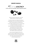
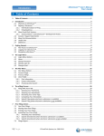
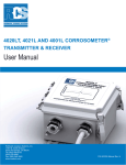
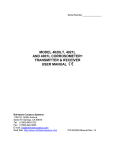
1
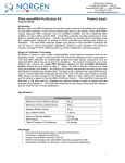
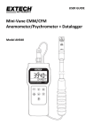
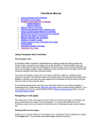
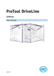
Operating Manual Localized Electronics Cleanliness Tester and Residue Extractor [Model: C3/C.I.] www.foresiteinc.com [email protected] (765) 457-8095 US patent #5,783,938 UK patent #2324374 China patent #ZL98107079.5 Hong Kong patent #1018313 Germany patent #19807580.4 © Foresite, Inc. 2014 Table of Contents 1. CONTACTS AND CUSTOMER SUPPORT 3 2. SPECIFICATIONS & SYSTEM DESCRIPTION 2.1. Specifications 2.2. System Overview 2.3. Principles of Operation 4 4 5 6 3. INSTALLATION & PRE-OPERATION CHECKS 3.1. Shipping Contents 3.2. Unpacking & Setup 3.3. Initial System Navigation Data Entry Screen Display Options Customer and Test Information Entry Test Parameter Setup Start and Stop Test Data Storage 7 7 8 10 4. SYSTEM OPERATING PROCEDURES 4.1. Initial System Checkout 4.2. Standard Testing Procedure 4.3. Data Storage and Retrieval 4.4. Daily and Weekly Operational/Maintenance Checks Daily Check Weekly Check 4.5. System Calibration/Verification Procedures Verification of System Current Calibration 20 20 21 25 26 27 2 Foresite, Inc. ♦ (765) 457-8095 ♦ www.foresiteinc.com 02-19-2015 – rev I 1. CONTACTS AND CUSTOMER SUPPORT For information regarding operation, maintenance, calibration or repair of your C3, please contact Foresite, Inc. at: Foresite, Inc. 1982 South Elizabeth Street Kokomo, IN 46902 (765) 457-8095 [email protected] www.foresiteinc.com For information regarding the ordering of consumables, please go to the C3 Consumables Reorder Information at the end of this Manual. To become fully acquainted with the operation and use of the C3, it is recommended that personnel within your organization become active in the following ways: Visit the Foresite website to receive information concerning the C3 and future development plans. Go to www.foresiteinc.com. Contact Foresite staff with questions or concerns at [email protected]. 3 Foresite, Inc. ♦ (765) 457-8095 ♦ www.foresiteinc.com 02-19-2015 – rev I 2. SPECIFICATIONS & SYSTEM DESCRIPTION 2.1. Specifications Dimensions: 24” W x 22” D x 21” H (61 cm x 56 cm x 53 cm) (with arm assembly removed, the height is 14” H (35 cm)) Weight: Approximately 75 pounds (34 kilograms) Power Requirements: 100 to 240 V AC, 1 Φ 50 to 60 Hz 5.0 A @ 120 V AC Included Components: Fun Tak Electrical verification cells (three cells, low, medium and high current levels) Consumables: Standard test cell (single use) (p/n CTC001SK) Box of (100) Cells Effective test region is 0.10 in2 Extraction solution Box of (2) 1 liter bags 4 Foresite, Inc. ♦ (765) 457-8095 ♦ www.foresiteinc.com 02-19-2015 – rev I 2.2. System Overview CPU Arm & Steam Head Assembly ESD Mat Monitor Solution Drawer Keyboard & Tray Storage Drawer Steam inlet Vacuum outlet Electrode Wing Sample collection reservoir Seal 5 Foresite, Inc. ♦ (765) 457-8095 ♦ www.foresiteinc.com 02-19-2015 – rev I 2.3. Principles of Operation The information gathered when using the C3 is intended to provide a measure of the cleanliness of a localized region of a circuit board. In addition, the C3 extracts a sample of the effluent from that localized region that can be used in further ionic analysis (such as ion chromatography). The C3, in conjunction with the extraction solution, has been designed to achieve effective ionic residue removal using a heated delivery system that consists of 3 stages: 1. Heat the extraction solution and deliver to the extraction site 2. Soak to allow solubilization of ionic species 3. Aspirate the solution into a collection cell This process cycle is repeated nine (9) times to allow effective removal of the surface contaminating residues from a region of approximately 0.1 in2. The extracted ionic residues are then collected for subsequent analysis. The nine cycles should produce a volume of effluent that will fill the cell reservoir to a level where the meniscus of the liquid falls between the solder mask regions of the test cell (see arrow in figure below) Simple “Clean” / “Dirty” analysis is performed using the C3 on-board measurement system. If more detailed analysis of residues is required, the extracted solution can be analyzed using more sophisticated techniques such as ion chromatography. The C3 on-board measurement system uses a sacrificial circuit board electrode, immersed in the extracted solution, to measure the electrical conductivity of the solution. By applying a known bias (10 volts) across the electrode terminals, a leakage current between the traces can be measured. Using the results from both SIR (surface insulation resistance) and ion chromatography testing, a leakage current of 250 μA has been established to identify when a current leakage event has occurred. These test parameter settings (250 µA and 120 sec.) produce relatively sensitive C3 tests and are commonly used on higher reliability electronics (e.g. IPC Class II and III). Another commonly used set of C3 test parameters is 500 μA and 60 seconds. These settings are used on electronics for less demanding applications and environments (e.g. IPC Class I). The design of the C3 assumes that the more corrosive or conductive the extracted residue, the quicker a current leakage event occurs. The less corrosive or conductive the residue, the longer it will take to reach a 250 µA event. The C3 system measures the time taken to reach a 250 µA current leakage event. Extensive testing has shown that C3 timing results that achieve the 250 µA event in less than 120 seconds correlate to residues that exceed the ionic contamination limits set forth by Foresite, Inc. Such results are identified as unacceptable and the tested sample 6 Foresite, Inc. ♦ (765) 457-8095 ♦ www.foresiteinc.com 02-19-2015 – rev I is considered “Dirty”. Timing events that take longer than 120 seconds to achieve a 250 µA current leakage event correlate to acceptable residue levels and that region of the board is considered “Clean”. 3. INSTALLATION & PRE-OPERATION CHECKS 3.1. Shipping Contents C3 system with integrated Mini PC & Wide Screen monitor Microsoft Windows operating system Detached movable arm Electrical verification cells (high, medium and low current levels) Dust cover cell Power cord Operating Manual Allen wrenches (5/64” for steam head; 3/32” for access panels) Standard test cells (one box, 100 per box) Extraction vials - 2 mL (one box, 100 per box) Caps for vials (one bag, 100 per bag) Extraction solution (two 1 liter bags) Fun Tak Water-resistant keyboard with built in touch pad 7 Foresite, Inc. ♦ (765) 457-8095 ♦ www.foresiteinc.com 02-19-2015 – rev I 3.2. Unpacking & Setup 1. Remove all components from the shipping container. Note: Note: Consideration should be given to the environment in which the C3 is located – a site that is as free of contaminants and corrosive elements as possible that could affect test results or the C3 unit. 2. Remove the wing nut and washer from the stationary post. 3. Ensure that the white spacer washer is centered on the post. Place the PC arm bracket on the arm post. Then place the movable arm on the stationary post as shown. Place the metal washer on the top of the arm and screw the wing nut down to secure the arm to the post. Adjust the tightness of the screw to control the ease of arm motion. 4. Connect the electrical, vacuum and water supply lines behind the test arm base. The electrical connection for the test head is a keyed barrel connector. Rotate the connector until the keyed position is found. Insert to full depth and rotate locking barrel. The vacuum connection is made with a push and click motion. When the fitting is fully seated, the retention clip will snap into place. Thread the extraction solution tubing assembly into the base fitting. Twist the fitting until finger tight. Attach the power cable to the connector on the back panel of the cabinet. 8 Foresite, Inc. ♦ (765) 457-8095 ♦ www.foresiteinc.com 02-19-2015 – rev I 5. Plug the white USB cable into the USB port on the back of the PC. 6. Plug in all the required power and VGA cables for the PC and monitor. 7. Remove the shipping cap from the extraction solution bag and replace it with the system one-way valve cap. (It is necessary to remove the solution feed line from the system cap first.) Purge any air bubbles that are trapped in the solution bag by holding the bag upright and squeezing out the trapped air. The one-way valve will keep air from re-entering the bag. 8. Replace the system feed line by hand tightening the fitting to the one-way valve. Lay the solution bag on the side in the fluid system drawer as shown. 9. Plug the power cable into a 100 - 240 V power outlet. Turn the unit on using the power switch located on the left side of the enclosure. The unit should be operational at this point. 10. Upon powering up the PC it should start and run the same as any office PC. Once the PC has started and loaded Windows, the C3/C.I. software icon should appear on the desktop. Click on the C3/C.I. desktop icon and the software should open and take you to the Test Homepage. 11. If this boot process does not occur and the Test Homepage does not appear, contact techsupport for further assistance. 9 Foresite, Inc. ♦ (765) 457-8095 ♦ www.foresiteinc.com 02-19-2015 – rev I 3.3. Initial System Navigation The C3 has many different options for operating via the PC interface. Those options control the system as shown below. The primary menu options found on the “Menu Tool Bar” are: • File • Edit • Calibration • View 10 Foresite, Inc. ♦ (765) 457-8095 ♦ www.foresiteinc.com 02-19-2015 – rev I • Control • Data analysis • Security • Help 11 Foresite, Inc. ♦ (765) 457-8095 ♦ www.foresiteinc.com 02-19-2015 – rev I Detailed Descriptions of the Primary Options File Menu In the file menu the user has the option to open/save test as well as create New/Load/Save Configurations based on user preferences. The open/save option allows the user to open a previously run test for review as well as save current test data to specific files via the browse option. The File menu is also where the Quit action is located. Edit Menu The Edit menu option is where the user can input User/Customer information, adjust test parameters, and select preferences. User Information User/Customer information allows entry of customer and test information into the test database. To change a data entry field, select the desired field and enter data as needed. To clear data use the backspace button. 12 Foresite, Inc. ♦ (765) 457-8095 ♦ www.foresiteinc.com 02-19-2015 – rev I Test Parameter Setup The Test Parameter Setup option is located in the “Edit” tab on the menu bar and allows for the inspection and changing of the default C3 system test parameter settings. Multiple setup screens are accessed from this screen using password control as described in the Security section. Descriptions of those screens are discussed in the Adjustment of Standard Testing Parameters Section of this manual. Preferences The Preferences option is where the user can select from different system options such as Auto Save Test Data, Warnings, Barcode Scanner, and selecting the saving location for Auto Save Test Data. 13 Foresite, Inc. ♦ (765) 457-8095 ♦ www.foresiteinc.com 02-19-2015 – rev I Calibration Menu The Calibration menu is where the user can calibrate the unit, pair cells, and validate cells. These options are password protected and can only be adjusted once the correct password has been entered into the Calibration “Log In” under the Security menu. Refer to the security section for further information on Password “Log In”. The unit is calibrated; the calibration cells are paired to the unit prior to delivery and should not need to be adjusted by the end user. In the event that the unit should fail a calibration check, please contact Technical Support for further assistance. The Validate cells option ensures the accuracy of the measured sensor current and verifies that the unit is properly calibrated. It can be verified by using the three electrical verification cells supplied with the C3. Those cells are matched to the serial number of the supplied unit. The results of this verification should produce current values within the range shown in following table. Cell Designation Low Medium High Minimum Maximum Current (μA) Current (μA) 209 219 450 460 662 672 Click on the Calibration tab and select Validate Cells. Once the Validate Cells option has been selected it will populate a dialog box with guided instructions on how to properly validate the system. Insert each test validation cell into the steam head and follow the instructions. Upon completion of the validation test, the system will show the measured values and say if the system has passed or failed the check. If all three current values fall within the specified limits, the system is considered calibrated and acceptable for production use. When this testing is completed, close the dialog box. 14 Foresite, Inc. ♦ (765) 457-8095 ♦ www.foresiteinc.com 02-19-2015 – rev I View Menu The view menu allows the user to select from different display options within the main test home screen. By checking the specific item it will select or de-select those items to be shown on the page. The checked items will be shown. Control Menu In the Control menu the user will have the option to activate/deactivate various pieces of equipment within the unit. This is where the user can select to start/stop a test, turn on/off the heat and vacuum, and toggle the pump line purge option. In this menu the user can also select to Reset the test number back to zero. The “Pump Line Purge” provides the controls necessary to test and purge the solution extraction system. The number of purge cycles is set to one hundred and fifty (150) at the factory. This number can be changed if needed. Pressing the Start button will cause the system to purge that set number of cycles and the screen will show a countdown as it pumps. The user can also stop the purge at any time by clicking Stop. 15 Foresite, Inc. ♦ (765) 457-8095 ♦ www.foresiteinc.com 02-19-2015 – rev I Data Analysis The Data Analysis menu allows the user to graph and analyze previous/current test data for the desired test/date range. By selecting the Data analysis option it will populate CI Graph Data Selection dialog box. Within the Data Selection box the user can input/select various information pertaining to the desired results they are wanting to see. The graphed data is based on the C.I. (Corrosivity Index) of the selected tests. 16 Foresite, Inc. ♦ (765) 457-8095 ♦ www.foresiteinc.com 02-19-2015 – rev I Security Menu The security menu is where the user can enter the “Log in” password so that the various testing parameters can be adjusted. This menu is also where the user can change the password for the unit to something that is easily remembered. In the “Log in” tab on the drop down menu, the user has an option to select from “Settings” or “Calibration”. The “Settings” tab is where the user will have the option to enter their password and then adjust various test settings and parameters for testing. Once the user has entered the correct password in the dialog box shown above they can then start using the now unlocked features. When the “Settings” log in password has been entered the user now has the option of adjusting the “Test Parameters”. 17 Foresite, Inc. ♦ (765) 457-8095 ♦ www.foresiteinc.com 02-19-2015 – rev I Once the “Test Parameters” has been opened, the user has the option of changing the parameters such as time, cycles per test, and heater temperature. 18 Foresite, Inc. ♦ (765) 457-8095 ♦ www.foresiteinc.com 02-19-2015 – rev I If the users selects the “Advanced” tab in the Test parameters it will give them the option to adjust items such as the pump cycle count, pump timing, and soak time. If at any time the users decides that they no longer want to keep the adjusted test parameters, they can simply click on the “Restore defaults” button on the bottom left of the dialog box and all of the test parameters will be returned to their Factory Default settings. 19 Foresite, Inc. ♦ (765) 457-8095 ♦ www.foresiteinc.com 02-19-2015 – rev I 4. SYSTEM OPERATING PROCEDURES 4.1. Initial System Checkout 1. Ensure that the steps described in the Unpacking & Setup Section of this manual have been performed correctly and that the PC and monitor turn on. 2. Verify that the extraction solution bag has a sufficient quantity of liquid and has been “purged” to remove any trapped air bubbles. Position the bag so that any remaining bubbles float away from the liquid outlet. 3. Insert a test cell into the steam head as shown. Raise the head and with the collection reservoir facing the front of the head, push the test cell up in the head using the base of the reservoir until the top of the wings are in-line with the steam head housing (see arrow in photograph at right). 4. Standard practice suggests handling the cell only by the wings. 5. As a standard practice, the extraction solution delivery system is purged one hundred and fifty (150) times prior to actually placing the C3 in a production environment. Click the PURGE icon to enter the Purge Menu screen. As the number of purge cycles is set to 150 at the factory, the system is initially setup to perform this procedure. Press the Start button to begin the process. Collect the purged solution by placing a beaker under the steam head, discard the purged solution once complete. 6. As a way to ensure that the system electrical calibration has not been affected during shipping, a verification of system current calibration is to be performed prior to actually placing the C3 system in a production environment (see the System Calibration/Verification Procedures Section of this manual). This verification consists of determining the actual measured current when each of the three Electrical Verification Cells (low, medium and high) are placed in the steam head. The resulting measured current values must fall within the limits set forth in the verification procedure. If the values fall outside of those limits, contact Technical Support at Foresite, Inc. 20 Foresite, Inc. ♦ (765) 457-8095 ♦ www.foresiteinc.com 02-19-2015 – rev I 4.2. Standard Testing Procedure After the extraction solution system conditioning (purging) and the electrical verification testing are successfully completed, the C3 is ready to be placed in a production environment. Foresite recommends the use of an ESD strap when working with components or assemblies that may have highly sensitive static areas. The C3 is equipped with a common ground location for convenience. The C3 can be user configured to meet any particular extracting/testing condition that is desired. However, extensive field and laboratory experience has established a standard set of testing conditions to be used for the vast majority of situations. Those standard parameters are loaded into memory at the factory. The following table lists the testing parameter sets for the Standard test cell. Standard C3 Extraction/Testing Parameter Sets Parameter Name Area of extraction (inch2) Total Test Time (sec) Check Current Time (sec) Limit Current (μA) Cycles per Test Preheat Temperature (ºF) Solution Heater Temperature (ºF) Pump Control - count Pump Control - time on (msec) Pump Control – time off (msec) Vacuum Time (sec) Soak Time (sec) Standard Test Cell P/N CTC001SK (High Reliability, e.g. IPC Class II & III) 0.10 180 120 250 9 210 255 6 300 700 2 20 Standard Test Cell P/N CTC001SK (Less Demanding, e.g. IPC Class I) 0.10 180 60 500 9 210 255 6 300 700 2 20 Detailed instructions concerning changing the standard parameters are provided in the Adjustment of Standard Testing Parameters Section of this manual. The changing of these parameters is under password protection. 1. Prior to beginning testing, the system must be allowed to warm up and stabilize. Turn on the extraction solution heater using the Heater icon located just under the menu tool bar. The red light on the steam head indicates that the heater is turned on. The light will first blink then stay on and finally begin to cycle once the heater is at the desired temperature. The heater will take several minutes to reach the set point temperature. 21 Foresite, Inc. ♦ (765) 457-8095 ♦ www.foresiteinc.com 02-19-2015 – rev I Upon initially turning on the system, the heater temperature is set to the system preheat temperature. At the start of the first test, the heater temperature changes to the solution heater temperature and stays at that temperature until the system is turned off and then restarted. Again, the heater will take several minutes to reach the desired extraction temperature. 2. Prior to starting a test, customer information must be input into the system database. This operation is accessed through the “Edit/User Information” tab. 3. Place the sample to be tested on the ESD mat in such a location that the area-ofinterest is within reach of the steam head. 4. Remove a test cell from the shipping tray, handling only by side wings on the cell. Insert the test cell as discussed previously. It is important that the cell be fully seated up into the steam head. 5. Lower the steam head with the test cell onto the area to be tested. Make sure that the red seal is fully compressed. 6. Begin the test process by pressing the green “Start” button of the main testing page. During testing a number of key parameters are displayed during this process. As shown, the temperature of the extraction solution heater is displayed [Temp (F)]. As the extraction process continues, the Status data line will change based on which phase of the extraction process is occurring. The extraction process will repeat the specified number of cycles as shown at Cycle. 22 Foresite, Inc. ♦ (765) 457-8095 ♦ www.foresiteinc.com 02-19-2015 – rev I 7. As the test progresses, the measured current at each measurement interval (250 msec) is plotted. Three result conditions are possible during testing. Those conditions are Clean, Dirty and Invalid. The two most likely outcomes are CLEAN and DIRTY. In the case of the clean event, the measured current did not exceed the specified Limit Current (μA) within the Check Current Time (sec). In the case of the dirty event, the specified Limit Current (μA) was exceeded in less than the Check Current Time (sec). The third result condition (INVALID) is most likely caused by a solution extraction error. In this case, the volume of liquid extracted up into the collection reservoir was not large enough to have the meniscus of the solution fall within the proper region of the test electrode (see photograph in Principles of Operation). If this occurs on a clean sample, the current will be less than approximately 70 μA, triggering an INVALID test condition. If this low liquid level event occurs on a highly contaminated sample, the 250 μA event limit, in this case, will probably occur and the result will report as dirty. There are two likely reasons for a low liquid level. First, if open vias are present within the test region, the extraction liquid will flow through the circuit board. This is usually taken care of by applying Kapton tape or Fun Tak to the backside of the board, sealing the vias. Second, the seal on the cell may be incomplete allowing liquid to leak out of the test area. 23 Foresite, Inc. ♦ (765) 457-8095 ♦ www.foresiteinc.com 02-19-2015 – rev I 8. At the completion of a test, it is necessary to save the data to the test database. If this step is not completed, a record of that test will be lost. Press the Save Data button to store the current test data, unless it is already set up to auto save. Raise the steam head and push down on the ejector bar to release the test cell. Remove the cell by pulling down on the wings of the cell. 9. In some cases, the collected sample is to be further analyzed using ion chromatography or some other chemical analysis test technique. In this case, snap off the retaining cap from the top of the test cell and transfer the sample to a clean sample bag or vial. Care must be taken to not contaminate the vial or the vial cap by touching the rim or cap seal with bare hands. 10. The majority of the extraction liquid is taken up into the collection reservoir during testing leaving little liquid left on the test assembly. Therefore, as a general statement, the part under test is left to air dry with no attempt to actively force clean or dry the tested region. If desired, the surface can be dried using a clean AlphaWipe lint-free cloth. 24 Foresite, Inc. ♦ (765) 457-8095 ♦ www.foresiteinc.com 02-19-2015 – rev I 4.3. Data Storage and Retrieval In order to keep a log of the testing that was conducted and of those results, it is necessary to save the results of each test before starting a new test. If a new test is started before the data is stored, the results of the previous test are purged from memory, unless auto save is set up by the user. To save a test the operator is to follow the same process as they would if they were saving a document on an MS office program. Locate the “File” tab on the top menu bar and click it to open the drop down menu. Select “Test” and then the “Save” option and enter the desired file name in the dialog box labeled “File Name”. Click the “Save” button and the test will be saved under the given name in the desired location. The user can also save test data by simply clicking on the disc icon on the tool bar at the top of the screen. However, by clicking the disc icon it will not allow you to save the test as a special name and will only save it by the user information (customer name), test number, and date code. To load a test from previously saved data files the operator is to follow the same steps above but instead of selecting “Save” they are to select “Open”. From there the operator can view a list of tests that have been saved and they can select the test for which they are wanting to recall data. Once selected the program will redisplay the test results including the graphed results. 25 Foresite, Inc. ♦ (765) 457-8095 ♦ www.foresiteinc.com 02-19-2015 – rev I 4.4. Daily and Weekly Operational/Maintenance Checks Daily The Computer and monitor are to be completely shut down and rebooted every day to ensure proper operation of the computer hardware/software. Note: Prior to shutting down or restarting the computer the user is to confirm that the C3’s power switch is in the OFF position. It is recommended that the solution extraction system be reconditioned each morning prior to running production tests. 1. From the Test Homepage Screen select the Purge button. 2. From the Purge Menu select the Start button and purge the system into a beaker for 150 cycles as was done during the Initial System Checkout. This purge operation should ensure that the extraction system will provide very low contamination extraction solution thus providing the most repeatable test results. Weekly It is further recommended that the current measurement calibration be verified weekly. Again this test is the same test conducted during the Initial System Checkout. Follow the procedure for Verification of System Current Calibration in the System Calibration/Verification Procedures Section of this manual. 26 Foresite, Inc. ♦ (765) 457-8095 ♦ www.foresiteinc.com 02-19-2015 – rev I ure s 4.5. Verification of System Current Calibration The accuracy of the measured sensor current can be verified using the three electrical verification cells supplied with the C3. Those cells are matched to the serial number of the supplied unit. The results of this verification should produce current values within the range shown in following table. Cell Designation Low Medium High Minimum Maximum Current (μA) Current (μA) 209 219 450 460 662 672 Insert each test verification cell into the steam head and follow the instructions given for validating cells. If all three current values fall within the specified limits, the system is considered calibrated and acceptable for production use. If any problems are encountered with this system please contact Technical Support at (765) 457-8095 or [email protected]. 27 Foresite, Inc. ♦ (765) 457-8095 ♦ www.foresiteinc.com 02-19-2015 – rev I