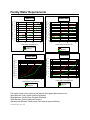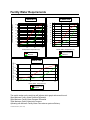
1
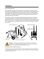
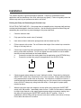
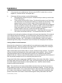
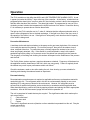
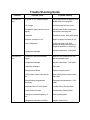
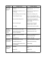
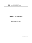
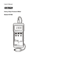
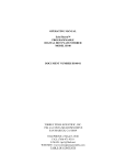
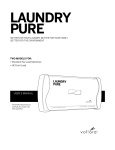
AFFINITY™ F-SERIES CHILLER
User Manual D2395
Lydall Industrial Thermal Solutions Inc.
Post Office Box 1000
775 Route 16
Ossipee, NH 03864 USA
Telephone: 603-539-3600 (Sales), 603-539-5005 (Service), Fax: 603-539-8484
O:\MANUALS\D4074 REV. D (05/16/2002) NMT
Table of Contents
Introduction
Facility Water Requirements
Equipment Precautions
Safety Precautions
Installation
Transporting
Placement
Electrical Requirements
Installing the External Strainer Accessory
Priming the Pump and Connecting the Coolant Loop
Cooling a Water-Cooled Condenser
Operation
Using the Controller
Changing the Set-Value Temperature
Safety Alarms
Preventive Maintenance
Trouble Shooting Guide
Warranty
Refrigeration Diagram
Fluid Flow Diagram
Electrical Schematic
O:\MANUALS\D3851 (08/31/2001)
Introduction
Congratulations on your purchase of an Affinity™ product.
I want to personally welcome you to the Lydall larger family. In October of 2001, Lydall purchased
Affinity Industries, in an effort to expand capability as a Total Thermal Solutions Provider.
Affinity’s chillers and heat exchangers complement Lydall’s existing wide array of Passive Thermal
Solutions, augmenting Lydall’s engineered thermal solutions for use in appliance, cryogenic,
building products, and automotive markets. Our group is market driven as a formidable thermal
solution manufacturer.
Lydall, Inc. is a New York Stock Exchange listed company (NYSE: LDL) headquartered in
Manchester, CT. Our company, with ten operations in the United States, France, one in
Germany, and Sales/Service Offices in Japan and Singapore, is recognized for working with
customers to satisfy their unique thermal solution needs, and for delivering high quality, innovative
products, and exceptional service.
Affinity™ products are high-precision specialty temperature-controlled equipment. The following
product manual is designed to help you realize the full value of your purchase.
We highly recommend that you read this manual in its entirety. The manual will assist your
company with the installation, operation, and routine maintenance of your Affinity™ product.
Please keep this manual readily accessible to operation and service personnel to ensure you get
the most out of our product.
If you have any questions about this model, or have other thermal solution needs, do not hesitate
to call our Sales department (603-539-3600) or the 24/7 Service department (603-539-5005).
Thank you for your confidence in our ability to meet and/or exceed your needs and expectations.
Sincerely,
John Tattersall
Group Vice President
Lydall Industrial Thermal Solutions, Inc.
O:\MANUALS\D3774 (01/11/2002)
Facility Water Requirements
FWA-022
4.5
Facility Water Flow Rate (gpm)
Facility Water Flow Rate (gpm)
FWA-015
4
3.5
3
2.5
2
1.5
1
0.5
0
5
15
25
6
5
4
3
2
1
0
35
5
Facility Water Temperature (C)
15
Recommended
Minimum
FWA-050
Facility Water Flow Rate (gpm)
Facility Water Flow Rate (gpm)
FWA-032
9.5
8.5
7.5
6.5
5.5
4.5
3.5
2.5
1.5
15
25
Facility Water Temperature (C)
Recommended
Minimum
35
16
14
12
10
8
6
4
2
5
15
25
Facility Water Temperature (C)
Recommended
Minimum
The model number on the serial tag will indicate which graph references this unit.
20psi Minimum Facility Water Pressure Differential
50psi Maximum Facility Water Pressure Differential
75psi Maximum Facility Water Inlet Pressure
Operating with Minimum Facility Water Flow reduces system efficiency.
O:\MANUALS\D5020 (06/21/1999)
35
Facility Water Temperature (C)
Recommended
Minimum
5
25
35
Facility Water Requirements
FWA-100
24
18
Facility Water Flow Rate (gpm)
Facility Water Flow Rate (gpm)
FWA-075
16
14
12
10
8
6
22
20
18
16
14
12
10
8
6
4
5
15
25
35
5
15
25
Facility Water Temperature (C)
Facility Water Temperature (C)
Recommended
Minimum
Recommended
Minimum
Facility Water Flow Rate (gpm)
FWA-120
30
25
20
15
10
5
5
15
25
35
Facility Water Temperature (C)
Recommended
Minimum
The model number on the serial tag will indicate which graph references this unit.
20psi Minimum Facility Water Pressure Differential
50psi Maximum Facility Water Pressure Differential
75psi Maximum Facility Water Inlet Pressure
Operating with Minimum Facility Water Flow reduces system efficiency.
O:\MANUALS\D5036 (06/05/1999)
35
Equipment Precautions
Failure to adhere to these precautions will void the warranty and may damage the chiller.
1.
This chiller has been shipped without coolant. Do not run it without connecting the coolant
lines and keeping them filled with the appropriate coolant. Never run the pump without
prime because it will be quickly ruined without liquid.
2.
Never use coolants which are incompatible with the components in the chiller’s coolant
loop. Some coolants may not damage the coolant loop components, but may significantly
derate the chiller’s coolant capacity. Never use automotive antifreeze or other
antifreeze containing silicates because this will cause the pump seals to fail.
Check with Lydall if there are questions about the coolant.
3.
Maximum storage temperature for the unit is 52°C (125°F).
4.
Heat generated by motors and electrical components must be dissipated. Allow sufficient
clearance around the unit to dissipate this heat.
5.
This chiller is designed for indoor use only. Do not operate the chiller in ambient
temperatures below 7°C (45°F) or above 40°C (104°). If the chiller has been exposed to
temperatures below 7°C, allow 24 hours at ambient temperatures above 7EC to warm the
oil in the compressor as well as the refrigerant before starting.
6.
If this unit contains refrigerant, there is an oxygen depletion risk that should be considered.
It must be placed in a room with adequate volume based on the amount of refrigerant in
the unit. If additional refrigeration equipment is in the room, additional space must be
provided. In the Placement section, under Installation, refer to the Warning: Oxygen
Depletion Risk for more details.
7.
The chiller is powered by three phase electricity; verify pump rotation before operating.
Rotation should be in the same direction as the arrow on the pump casing. Only qualified
electrical service technicians should switch legs on three phase power to change pump
rotation. The compressor is not sensitive to phase. Pump rotation must be verified when
the chiller is connected to a different circuit.
8.
Routinely inspect the pump inlet strainer located in the reservoir for debris. Turn off the
chiller, then remove and clean the strainer as needed to permit free flow of coolant. Keep
foreign debris from entering the coolant line while the strainer is removed. Hint: A plastic
sandwich bag may be used to wrap the strainer to contain most of the debris. Failure to
keep the strainer clean will reduce the flow of coolant and damage the pump.
9.
Regularly clean the screen in the assembly at the chiller’s inlet for Facility Water. To
clean, turn off the chiller, shut off the supply of Facility Water to the chiller, and remove the
screen. Clean the strainer as needed, then reinstall.
Equipment Precautions
10.
This chiller exhausts the heat it extracts to Facility Water. The Facility Water should never
exceed 30°C (86°F). The Facility Water flow will be controlled by the water valve at
Lydall’s condenser. See the section on Facility Water Requirements for the exact flow,
pressure and temperature required for this unit.
11.
A water-cooled unit must never be operating without the Facility Water connected and
flowing at the specified rate indicated in the Facility Water Requirements section. The unit
will be damaged in a very short time period if operated without Facility Water.
12.
Do not operate the chiller at coolant temperatures above or below the values it was
specified to deliver.
13.
Do not run the chiller with cooling loads that exceed its factory rated cooling capacity.
14.
Do not operate damaged or leaking equipment.
15.
The chiller must not be transported unless suitably protected. Original factory packaging
in good condition or equivalent is required. Request air-ride trucks when transporting over
land.
16.
The chiller should be thoroughly drained and the coolant lines blown dry with low pressure
compressed air before shipping or storing.
17.
Modifying the chiller without express written consent from Lydall will void the warranty.
F:\MANUALS\D3797 (10/03/2002)
Safety Precautions
1.
Heed all warning labels. Do not remove.
2.
Do not operate the chiller with the bonnet removed. The bonnet protects personnel from
rotating parts and hot surfaces and also protects the chiller’s components.
3.
Connect the chiller to a properly fused disconnect box in compliance with the National
Electric Code (NFPA-70) as well as state and local codes for American usage, or local and
national codes for European usage. Maximum fuses must not exceed the maximum rating
found on the serial tag on the electrical box. The voltage, phase, and frequency of the
power source must also match the requirements specified on the serial tag. To reduce
the risk of electric shock:
!
Disconnect electrical power before opening the electrical box, except for
the checking of the phase reverse relay or phase monitor if included with
this unit (phase reverse relays or phase monitors will never be included in
single phase units). Power must be applied in order for the phase reverse
relay or phase monitor to indicate phase sequence.
!
Do not operate with electrical box door open.
!
Refer servicing of electrical box components to qualified/certified personnel.
!
Do not operate equipment with damaged electrical power cords.
!
Turn off the unit and disconnect electrical power before servicing or
moving.
!
Properly ground the unit.
4.
Coolant lines, filters, and other components which connect to the chiller must be capable
of withstanding the maximum pressure that the pump in the chiller can deliver at the
maximum expected temperature.
5.
The coolant loop has not been designed for potable water applications. Do not use the
chiller for potable water. Never hook the water lines of a water-cooled unit to a potable
water source or immerse a hose connected to a potable water source in the reservoir
without providing back flow protection. A loss of pressure in the water source could lead
to a back flow of the fluid in the unit, resulting in a possible contamination of the potable
water source.
6.
Vapors of some alcohol based antifreezes as well as other coolants may cause explosion if
exposed to flame or spark.
7.
Certain antifreezes may be poisonous if ingested.
F:\MANUALS\D3799 (10/03/2002)
Installation
Transporting
An Affinity™ chiller rolls easily on its four swivel casters. The brakes must be off on the two
locking casters when moving the unit. Roll the chiller gently to its operating location. The
cushioned casters will help to dampen shock. Lock the casters when the chiller is in place. If the
chiller is carried with a forklift, proceed slowly and carefully to avoid jarring the chiller. Insert the
forks the longer dimension to catch both of the reinforcing rails of the chassis, taking care to
prevent damage to the casters.
If the chiller will be shipped, protect it from shock and vibration or the warranty will be void. The
chiller must not be transported unless suitably protected. Original factory packaging in good
condition or equivalent is required. Request air-ride trucks when transporting over land.
Drain all coolant lines and blow them dry with low pressure air before transporting or storing the
unit. Lydall will not accept any unit containing measurable amounts of fluid. Fluid left in the unit
during shipping may damage components within the unit. Such damage is not covered by
warranty.
Placement
Select a level location near the application, free from dripping or spraying moisture and excessive
dust. Keep the coolant lines short to allow the pump to provide maximum pressure and flow to the
application. If the chiller will be placed more than 25 feet from the application, call Lydall to
discuss placement and how it might affect performance.
Units with non-pressurized reservoirs should never be installed more than 25 feet below the
process or overflow may occur. Distances may vary slightly due to elevations above sea level.
Call Lydall service (603-539-5005) for more information.
WARNING: Oxygen Depletion Risk
In the event of a refrigerant leak, refrigerant gas may displace oxygen that could result in
suffocation and death. Never place the chiller in a room that is smaller than the minimum room
volume requirement as defined below. If the room is ventilated, the air distribution system must be
analyzed to determine the worst case distribution of leaked refrigerant. A leak detector alarm
device is always required in a ventilated room that does not meet the minimum room volume given
below. Assure adequate and sufficient room volume and ventilation before placing a chiller that
contains refrigerant in a room. Contact Lydall at 1-603-539-5005 if you have any concerns or
questions.
Pounds of refrigerant charge can be read directly from the nameplate on your chiller. Remember
to include in your calculation any refrigerant that may be stored in any other containers.
Minimum Room Volume = Pounds of refrigerant x 110 cubic feet
Example: Two chillers are placed in a room, each containing 6 pounds of refrigerant. The
minimum room volume shall be 12 x 110 cubic feet, or 1,320 cubic feet.
Installation
Electrical Requirements
Connect the chiller to a properly fused disconnect box in compliance with the National Electric
Code (NFPA-70) as well as state and local codes for American usage, or national and local codes
for European usage. Maximum fuse sizes in the disconnect box must not exceed the maximum
ratings specified on the serial tag of the chiller (found on the electrical box near where the power
cord connects). The voltage, phase, and frequency of the power source must also match the
requirements specified on the serial tag.
Note: Affinity™ models that can operate at 208-230 Volts 60 Hertz have been set at the factory
for 208-230 volt operation. If the operating voltage will be greater than 220 volts, a qualified
electrician should remove the red wire from the contactor and replace it with the orange wire taken
from the dummy fuse block. Attach the red wire to the dummy fuse block as shown in the diagram
below. All voltages may not be compatible with this unit. See the unit’s serial tag for the correct
voltage range.
TYPICAL CONFIGURATION
ELECTRICAL SCHEMATIC
CONNECT FOR
SYSTEM VOLTAGE
CT1
75VA
INTERCHANGE
RED AND ORN
TO CHANGE VOLTAGE
REMOVED FROM
POWER TERMINAL
PRIMARY CONNECTIONS
NOT USED MUST BE
ISOLATED AND CAPPED
NOTE: IN SOME CASES PRESSURE SCREW TERMINAL BLOCKS
ARE USED IN PLACE OF FASTON TERMINATIONS
24 VAC
BLU
YEL
Warning: To reduce the risk of electric shock, do NOT remove cover from the
electrical box. It contains exposed high voltage wires. Refer servicing to qualified
personnel. Disconnect power to the chiller before servicing.
Installing the External Strainer Accessory
The strainer accessory comes with extra fittings to allow arrangement in different configurations.
Any combinations of these fittings is acceptable. Lydall recommends that the strainer be installed
on the Facility Water inlet port.
Installation
The strainer requires a regular maintenance schedule. Frequency will be based on the
application and the cleanliness of the fluid, which can vary greatly. Failure to regularly check the
strainer may result in poor performance and/or unit failure.
Priming the Pump and Connecting the Coolant Loop
DO NOT RUN THE PUMP DRY. If the pump does not establish prime, the pump shaft seal may
overheat and be damaged in less than a minute. Use the following instructions when filling and
assembling the coolant lines to prevent damage to the pump shaft seal.
1.
Close the reservoir drain.
2.
Fully open the flow control valve (if included).
3.
Have extra coolant to add as the pump primes and the coolant loop fills.
4.
Fill the reservoir with coolant. Do not fill above the height of the coolant loop connection
fittings or fluid may leak out.
5.
Connect the coolant lines from the application to the FPT (female pipe thread) fittings near
the top of the chiller as follows. Do not over tighten the insert and do not use a sealant
that will lock the male threads to the female threads.
a.
Connect the coolant line coming back from the application to the RETURN fitting.
b.
Connect the coolant line going to the application to the SUPPLY fitting.
RETURN
SUPPLY
6.
Check for proper pump rotation by “bump” starting the chiller. Bump start by placing the
ON/OFF/SET switch in the ON position for one or two seconds. Pump rotation should be
in the same direction as the arrow on the pump. If the direction of rotation is incorrect, a
qualified electrical technician should exchange any two of the wires in the incoming power
source (DO NOT change any wiring inside the chiller). Check again for proper pump
rotation as above.
7.
When the previous steps are complete, turn the chiller on by placing the ON/OFF/SET
switch in the ON position. Immediately check for flow. If within five seconds no turbulence
is visible in the reservoir or the supply pressure gauge shows no pressure reading, shut
the chiller off by placing the ON/OFF/SET switch in the OFF position. If flow is
established, continue filling until the reservoir level rises to within a few inches of the top.
Do not allow the reservoir to overflow.
Installation
8.
If the pump does not establish prime, disconnect the SUPPLY coolant line to vent any
trapped air, reconnect the line, and repeat step 7.
9.
If the pump still does not prime, use the following steps:
a.
Disconnect both coolant lines (have a container handy to catch any overflow from
the RETURN fitting).
b.
Force coolant into the SUPPLY fitting. The fluid will force the air out of the lines in
the chiller and out of the pump head, causing it to escape into the reservoir. If tap
water will be the source of coolant, simply connect the tap water line to the
SUPPLY fitting and turn on the tap. If a source of coolant other than tap water will
be used, elevate the coolant a few feet above the chiller, connect to the SUPPLY
fitting, and let gravity force the air out into the reservoir. Remember to have a
container handy to catch any overflow from the RETURN fitting.
c.
Reconnect the coolant lines and repeat step 7. Stop filling when the reservoir is
full to within a few inches of the top. Do not allow the reservoir to overflow.
A stainless steel mesh strainer attaches to the pump suction port near the bottom of the reservoir.
It can easily be removed for cleaning. First turn the pump off, then pull off the strainer, rinse it
clean, and push it back on. To protect the pump, routinely inspect the strainer to be sure it is
clean and properly attached. Hint: If the strainer is coated with debris, wrap it with a plastic
sandwich bag before pulling it off to prevent most of the debris from escaping into the reservoir.
Cooling a Water-Cooled Condenser
Never hook the cooling lines of a water-cooled unit to a potable water supply without providing
back flow protection. A drop in pressure in the water supply could cause back flow, resulting in
the possible contamination of the potable water supply.
Water-cooled chillers require Facility Water to cool the condenser during operation. The amount
of flow is controlled automatically by a valve Lydall installs on the condenser. See the Facility
Water Requirements section of this manual for the specific flow, temperature and pressure
needed for this unit. Failure to connect Facility Water to the unit and supply the correct amount of
flow may severely damage the unit in an extremely short period of time.
Connect the Facility Water supply to the "WATER IN" fitting at the bottom of the chiller. Connect
the Facility Water return to the "WATER OUT" fitting. Use connecting lines of the size indicated on
the coolant diagram (inside diameter) to reduce pressure loss. Install the external strainer
accessory as previously instructed.
Note: The coolant lines of all water-cooled chillers have been blown dry with low pressure air
before shipping to protect the units from freezing and subsequent damage. This may cause the
condenser to be dry which, in turn, could result in failure to start upon initial start-up (there could
be no water in the condenser to absorb the heat). This is easily corrected by pressing the high
pressure reset switch a few times to initiate flow through the Facility Water side of the chiller.
F:\MANUALS\D3889 (05/16/2002)
Operation
Using the Controller
This Affinity™ chiller comes standard with a FUJI 1/16 DIN temperature controller. This controller
is a programmable microprocessor, which offers many more features than are necessary to master
at this point. If more than the basic instructions provided in this manual will be needed, call Lydall
service (603-539-5005) for technical assistance or consult the FUJI Instruction Manual.
EC
Affinity
C
H
PV
L
8.
SV
w
PV/SV
8.
v
SEL
8.
v
DATA
8.
v
ENT
PXZ-4
Place the ON/OFF/SET switch on the control box (if included with this chiller) or the chiller’s
control panel near the Fuji controller in the SET position. SET activates the control display but
does not turn on the refrigeration and pump systems of the chiller. Four dots will appear on the
display, then in 3-4 seconds the temperature of the coolant will appear plus an indicator light next
to PV. Indicator lights next to C, H, or L may also appear. The function of these lights will be
discussed later in the section on Safety Alarms.
Press PV/SV until the indicator light appears next to SV to display the Set-Value temperature.
The Set-Value temperature can be changed to any temperature within the range programmed for
this Affinity™ model. Note: Pressing PV/SV allows toggling the indicator light between PV, the
actual process coolant temperature, and SV, the Set-Value temperature.
Changing the Set-Value Temperature
Change the Set-Value temperature by pressing PV/SV until the indicator light appears next to SV.
Then directly under the digit in the display to be changed, press (^) and the digit will start blinking.
To increase the digit value, press (^) under the blinking digit as many times as necessary. To
decrease the digit value, press (v) at the left side of the controller. Press (^) under the next digit
value to be changed and repeat the process. When all the digits are set to the desired value and
with one digit still blinking, press the red (ENT) key at the far right of the controller to enter the
new Set-Value temperature.
Operation
A display of letters or numbers which do not indicate temperature may appear. SEL or DATA was
probably inadvertently depressed. The FUJI Instruction Manual explains the use of SEL and
DATA functions which are used solely in setting the basic program of the microprocessor. Press
PV/SV to return to either the PV or SV display.
The controller comes pre-programmed according to the Affinity™ model selected. If the additional
features programmed into the controller will be needed, consult the FUJI Instruction Manual, or
call Lydall service for technical assistance. The highest and lowest SV programmed into the
controller depends upon the model selected.
Caution: Never program in a Set-Value temperature of more than 32EC (90EF) unless this
Affinity™ model is specially modified to operate at higher coolant temperatures. Never program in
a Set-Value temperature of less than 5EC (40EF) unless a suitable antifreeze is used as coolant,
AND the chiller is designed to operate at below freezing temperatures.
Turn the whole system on by placing the ON/OFF/SET switch in the ON position. The Set-Value
temperature can be changed with the switch in either the ON or SET position.
Air bubbles will be visible rising in the reservoir as the pump forces air out of the coolant loop.
After the air has been purged from the coolant loop, a steady turbulence may be seen in the
reservoir. This turbulence mixes the coolant to deliver more precise temperature stability in the
coolant supply than the controller indicates.
Safety Alarms
The LOW LEVEL indicator light and the corresponding audible alarm actuate when the coolant
level in the reservoir is low and needs to be replenished. This indicator light does not actuate with
the ON/OFF/SET switch in the SET position.
The FAULT light comes on if too little coolant is circulating through the heat exchanger. The
FAULT light comes on momentarily upon start-up until the pump establishes sufficient flow. The
FAULT indicator does not actuate with the ON/OFF/SET switch in the SET position.
If the FAULT light remains on for more than a few seconds, the chiller should be turned off and the
reason for loss of circulation determined and corrected.
Caution: Although the FAULT light alerts the operator that no coolant is flowing, the operator
must not assume proper circulation through equipment external to the chiller if the light does not
appear. A bypass system built into the chiller to protect the pump may satisfy circulation
requirements within the chiller even though flow outside the chiller is blocked. For example,
turning the flow control valve on the chiller to no external flow does not actuate the light; similarly,
a wheel of a forklift truck standing on an external cooling line, thus stopping the flow to the
application, will not actuate the fault light.
Operation
The FUJI controller on this chiller has HIGH and LOW TEMPERATURE ALARM LIGHTS: H and
L appear just under the Affinity™ logo at the top of the controller. At the factory, a technician has
programmed the alarm light to come on under H if the circulating coolant is above the temperature
that this chiller has been set to deliver. The alarm light under L is programmed to come on if the
circulating coolant is below the temperature the chiller has been set to deliver. Consult the factory
if it is necessary to operate above or below these limits.
The light on the FUJI controller next to C, when lit, indicates that the refrigerant solenoid valve is
open to allow refrigerant to flow to the heat exchanger. If the light is on most of the time, most of
the capacity of the chiller is in use. If the light is on infrequently, much less than the full capacity
of the chiller is being used.
Preventive Maintenance
A stainless steel mesh strainer attaches to the pump suction port near the bottom of the reservoir.
It can easily be removed for cleaning. First turn the pump off, then pull off the strainer, rinse it
clean, and push it back on. To protect the pump, routinely inspect the strainer to be sure it is
clean and properly attached. Hint: If the strainer is coated with debris, wrap it with a plastic
sandwich bag before pulling it off to prevent most of the debris from escaping into the reservoir.
The frequency of checking and cleaning this strainer will depend on the cleanliness of the process
and the fluid.
The Facility Water strainer requires a regular maintenance schedule. Frequency will be based on
the application and the cleanliness of the fluid, which can vary greatly. Failure to regularly check
the strainer may result in poor performance and/or unit failure.
Check the strainers a week or two after starting the unit, then develop your own schedule for
checking and cleaning the strainers based on experience.
Decommissioning
Decontamination procedures are not required or applicable as there are no hazardous materials
used within this unit. The refrigerant used in this unit is environmentally friendly (a non-ozone
depleting HFC) and poses no hazard to the environment. However, the refrigerant must be
recovered by a qualified refrigeration service technician in accordance with all applicable laws.
When decommissioning, remove all fluids by opening all drains and placing the fluid in appropriate
containers. After all flow has ceased, purge the lines with low pressure air.
The unit is comprised of metals that may be recycled. The significant metals which make up the
unit are as follows:
‚
Cold-rolled steel
‚
Stainless steel
‚
Copper
There are no significant amounts of plastics or other materials incorporated into this unit. Recycle
metals appropriately.
F:\MANUALS\D8574 (05/16/2002)
Trouble Shooting Guide
Problem
Unit does not
start
Unit does not
cool
Possible Cause
Possible Remedy
No power to unit, breaker tripped
Verify correct power is applied, close
breaker after correcting fault
Low voltage
Check electrical service to unit
Refrigeration high pressure cut-out
tripped
Manually reset button on pressure
switch after correcting fault
Loose wire
Disconnect power, then check wiring
Defective contactor or coil
Repair or replace contactor or coil
Loss of refrigerant
Locate and repair leak, then
recharge with type and amount of
refrigerant specified on serial tag
Compressor damaged
Replace compressor - Call Lydall
Compressor internal thermostat
tripped
Allow time for compressor to cool
and automatically reset
Compressor damaged
Replace compressor - Call Lydall
Evaporator damaged
Call Lydall
Microprocessor failure
Replace microprocessor
Facility Water control valve set too
low
Reset Facility Water control valve Call Lydall
Microprocessor programmed
incorrectly
Reprogram microprocessor - Call
Lydall
Insufficient flow of Facility Water
Increase flow of Facility Water
Facility Water too warm
Provide cooler Facility Water
Cooling load exceeds capacity of
unit
Reduce cooling load
Refrigeration solenoid coil failure
Replace solenoid coil
Problem
Unit does not
cool (continued)
Pump leaks
Excessive noise
on Start-Up
Pump motor
overheats
Possible Cause
Possible Remedy
Loss of refrigerant
Locate and repair leak, then
recharge with type and amount of
refrigerant specified on serial tag
Solid State Relay failure
Replace Solid State Relay
Solenoid valve stuck shut
Repair or replace solenoid valve
Defective refrigeration low pressure
cut-out
Repair or replace low pressure cutout
Malfunctioning thermal expansion
valve
Replace thermal expansion valve
Pump damaged, loss of flow
Replace pump
Hot gas bypass valve setting too
high
Call Lydall
Hot gas bypass valve stuck open
Repair or replace valve
Faulty pump casing
Replace pump assembly
Shaft seal damaged
Replace shaft seal
Pump housing O-Ring damaged
Remove pump and rebuild
Improper fluid
Call Lydall
Low voltage
Check electrical service to unit
Wrong voltage taps used on
transformer
Connect to proper taps
Contactor or coil failure
Replace contactor or coil
Pump overload protection set too
high
Reset pump thermal overload relay,
or replace if faulty
Improper voltage supplied
Correct voltage
Problem
Noisy
compressor
Level light
remains on
Fault light
remains on
Level light does
not work
Low coolant
flow
Possible Cause
Possible Remedy
Flooding of refrigerant into
crankcase
Warm crankcase if unit has been off
for a long period or has been left in a
cool ambient for more than a few
hours
Worn compressor
Replace compressor - Call Lydall
Refrigeration high pressure cut-out
set too high
Adjust setting
Refrigeration low pressure cut-out
set too low
Adjust setting
Low coolant level
Check for leaks, then fill reservoir
Reservoir level switch float stuck
Clean reservoir and level switch
Time delay relay malfunction (when
used)
Replace time delay relay
Level switch failure
Replace level switch
Low coolant flow
See Problem; Low coolant flow
No coolant flow
See Problem; No coolant flow
Flow switch sticking
Disassemble flow switch, clean and
reinstall, or replace
Time delay relay has not timed out
(when used)
Wait for time delay relay to time out
Lamp burned out
Replace lamp
Level switch failure
Replace level switch
Pump suction strainer clogged
Remove strainer, clean and reinstall
or replace
Pump rotating backwards
Reverse one electrical phase
Flow control valve not fully open
Open flow control valve
Problem
Low coolant
flow (continued)
No coolant flow
Chiller cools
well below the
desired SetPoint
Possible Cause
Possible Remedy
Pressure relief valve set too low
(unless not adjustable)
Adjust pressure relief valve to
specification
Low coolant level in reservoir
Fill reservoir to proper level
Restriction in coolant lines external
to chiller
Eliminate restrictions in coolant lines
external to chiller
Frozen evaporator
Call Lydall
Flow switch clogged
Disassemble flow switch, clean and
reinstall, or replace
Pump not primed
Prime pump
Pump suction strainer clogged
Remove and clean strainer, then
reinstall
No coolant in reservoir
Repair any leaks, then fill reservoir
Pump overload tripped
Wait 5 minutes for overload to reset
Pump motor shaft bound to seal
Replace pump or renew seal
Pump housing improperly torqued
Remove pump, torque to
specifications, test, and reinstall
Damaged pump
Replace pump
Frozen evaporator
Call Lydall
Clogged line or closed valve in
external piping
Check external piping for dirt or
closed valve
Leak(s) in external piping
Repair leaks as needed
Microprocessor programmed
incorrectly
Reprogram microprocessor - Call
Lydall
Malfunctioning solenoid valve
Repair or replace solenoid valve
Solid State Relay failure
Replace Solid State Relay
Microprocessor failure
Replace microprocessor
Problem
Chiller shuts
down during
operation
Possible Cause
Possible Remedy
Refrigeration high pressure cut-out
set too low
Adjust and reset refrigeration high
pressure cut-out
Refrigeration low pressure cut-out
set too high
Adjust and reset refrigeration low
pressure cut-out
Water modulating valve set too high
Adjust water modulating valve
Excess refrigerant charge
Remove excess refrigerant, then
charge to specifications on serial tag
Pump overload setting too low
Adjust and reset pump thermal
overload relay to specifications, or
replace if faulty
Pump overload tripped
Determine cause, if pump is
damaged, repair or replace
Low voltage
Check electrical service to chiller
Too much
recirculating
pressure to
process
Flow control valve set too high
Throttle flow control valve
Pressure relief valve set too high
(unless not adjustable)
Adjust pressure relief valve
Compressor
does not run
Compressor internal thermostat
tripped
Allow time for compressor to cool
and automatically reset
Motor burned out
Replace - Call Lydall
Discharge pressure too high
Check Facility Water for blockage
Condenser fan(s) not on
Check motor(s) and wiring
Refrigeration high pressure cut-out
set to automatic
Check settings
Loose wire
Disconnect power to unit, then check
wiring
Broken RTD
Replace RTD
Microprocessor failure
Replace microprocessor
Compressor
turns on and off
automatically
Temperature
display reads
incorrectly
Problem
Microprocessor
does not work
F:MANUALS\D3635 (05/16/2002)
Possible Cause
Possible Remedy
5 second delay has not timed out
Wait at least 5 seconds after turning
on
Microprocessor programmed
incorrectly
Reprogram microprocessor - Call
Lydall
Microprocessor failure
Replace microprocessor
Warranty
The Lydall Limited Warranty
Twelve-Month Warranty
Parts and Labor
Lydall Industrial Thermal Solutions Inc. warrants this product to the original Owner for a period of
twelve (12) months from the date of shipment. Lydall will repair, or, at its discretion, replace any
part found to contain a manufacturing defect in material or workmanship, without charge to the
Owner, for twelve months from date of shipment. Shipping costs are excluded from warranty.
Service labor will be at no charge during the warranty period as long as the labor is supplied at
the Lydall plant in Ossipee, New Hampshire, or by a Lydall approved service provider.
Replacement or repaired parts will be warranted only for the un-expired portion of the original
Warranty. To obtain prompt warranty service, contact Lydall, PO Box 1000, Ossipee, New
Hampshire, 03864, USA.
Before returning any equipment to Lydall for repair, it is necessary to contact the Lydall Service
Department for a Return Material Authorization number and an authorized service depot location
where the repairs will be completed.
This Warranty does not cover the following: Damage or failure of any part caused by accident,
customer shipping, storage, misuse, customer modification, fire, flood, Acts of God, or resulting
from failure to properly install, operate, or maintain the product in accordance with the printed
instructions provided in the User Manual. As noted in the User Manual, any modification of the
unit without expressed written consent from Lydall will void the warranty.
In no event shall Lydall be liable for any repairs or service or any consequence of any repair or
service that are not performed in strict accordance with all applicable city, county, state, and
federal laws.
Further limitations and exclusions: This Warranty is in lieu of any other warranties, expressed or
implied, including merchantability or fitness for a particular purpose. In no event shall Lydall be
liable for any consequential or incidental damages that the Owner may incur resulting from
purchase or use of this Lydall product. The buyer's sole and exclusive remedy and the liability
limit of Lydall, for any loss whatever, shall not exceed the purchase price paid by the purchaser for
the Lydall product on which a claim is made.
Lydall Industrial Thermal Solutions Inc.
Post Office Box 1000
775 Route 16
Ossipee, NH 03864 USA
Telephone: 603-539-3600 (Sales), 603-539-5005 (Service), Fax: 603-539-8484
F:\MANUALS\D3777 (05/06/2002)