1
ACCES I/O PRODUCTS INC
10623 Roselle Street, San Diego, CA 92121
TEL (858)550-9559 FAX (858)550-7322
MODEL RDAG12-8(H)
USER MANUAL
FILE: MRDAG12-8H.Bc1
Notice
The information in this document is provided for reference only. ACCES does not assume any liability
arising out of the application or use of the information or products described herein. This document may
contain or reference information and products protected by copyrights or patents and does not convey any
license under the patent rights of ACCES, nor the rights of others.
IBM PC, PC/XT, and PC/AT are registered trademarks of the International Business Machines Corporation.
Printed in USA. Copyright 2000 by ACCES I/O Products Inc, 10623 Roselle Street, San Diego, CA 92121.
All rights reserved.
Warranty
Prior to shipment, ACCES equipment is thoroughly inspected and tested to applicable specifications.
However, should equipment failure occur, ACCES assures its customers that prompt service and support
will be available. All equipment originally manufactured by ACCES which is found to be defective will be
repaired or replaced subject to the following considerations.
Terms and Conditions
If a unit is suspected of failure, contact ACCES' Customer Service department. Be prepared to give the unit
model number, serial number, and a description of the failure symptom(s). We may suggest some simple
tests to confirm the failure. We will assign a Return Material Authorization (RMA) number which must
appear on the outer label of the return package. All units/components should be properly packed for handling
and returned with freight prepaid to the ACCES designated Service Center, and will be returned to the
customer's/user's site freight prepaid and invoiced.
Coverage
First Three Years: Returned unit/part will be repaired and/or replaced at ACCES option with no charge for
labor or parts not excluded by warranty. Warranty commences with equipment shipment.
Following Years: Throughout your equipment's lifetime, ACCES stands ready to provide on-site or in-plant
service at reasonable rates similar to those of other manufacturers in the industry.
Equipment Not Manufactured by ACCES
Equipment provided but not manufactured by ACCES is warranted and will be repaired according to the
terms and conditions of the respective equipment manufacturer's warranty.
General
Under this Warranty, liability of ACCES is limited to replacing, repairing or issuing credit (at ACCES
discretion) for any products which are proved to be defective during the warranty period. In no case is
ACCES liable for consequential or special damage arriving from use or misuse of our product. The
customer is responsible for all charges caused by modifications or additions to ACCES equipment not
approved in writing by ACCES or, if in ACCES opinion the equipment has been subjected to abnormal use.
"Abnormal use" for purposes of this warranty is defined as any use to which the equipment is exposed other
than that use specified or intended as evidenced by purchase or sales representation. Other than the above,
no other warranty, expressed or implied, shall apply to any and all such equipment furnished or sold by
ACCES.
Page iii
Table of Contents
Chapter 1: Introduction . . . . . . . . . . . . . . . . . . . . . . . . . . . . . . . . . . . . . . . . . . . . . . 1-1
Description . . . . . . . . . . . . . . . . . . . . . . . . . . . . . . . . . . . . . . . . . . . . . . . . . . . . . . . . . . . 1-1
Specifications . . . . . . . . . . . . . . . . . . . . . . . . . . . . . . . . . . . . . . . . . . . . . . . . . . . . . . . . . 1-3
Chapter 2: Installation . . . . . . . . . . . . . . . . . . . . . . . . . . . . . . . . . . . . . . . . . . . . . . 2-1
CD Installation . . . . . . . . . . . . . . . . . . . . . . . . . . . . . . . . . . . . . . . . . . . . . . . . . . . . . . . . .
Directories Created on the Hard Disk . . . . . . . . . . . . . . . . . . . . . . . . . . . . . . . . . . . . . . .
Getting Started . . . . . . . . . . . . . . . . . . . . . . . . . . . . . . . . . . . . . . . . . . . . . . . . . . . . . . . .
Calibration . . . . . . . . . . . . . . . . . . . . . . . . . . . . . . . . . . . . . . . . . . . . . . . . . . . . . . . . . . . .
Installation . . . . . . . . . . . . . . . . . . . . . . . . . . . . . . . . . . . . . . . . . . . . . . . . . . . . . . . . . . . .
Input/Output Pin Connections . . . . . . . . . . . . . . . . . . . . . . . . . . . . . . . . . . . . . . . . . . . . .
2-1
2-1
2-3
2-6
2-6
2-6
Chapter 3: Software . . . . . . . . . . . . . . . . . . . . . . . . . . . . . . . . . . . . . . . . . . . . . . . . . 3-1
General . . . . . . . . . . . . . . . . . . . . . . . . . . . . . . . . . . . . . . . . . . . . . . . . . . . . . . . . . . . . . . 3-1
Command Structure . . . . . . . . . . . . . . . . . . . . . . . . . . . . . . . . . . . . . . . . . . . . . . . . . . . . 3-1
Command Functions . . . . . . . . . . . . . . . . . . . . . . . . . . . . . . . . . . . . . . . . . . . . . . . . . . . . 3-3
Error Codes . . . . . . . . . . . . . . . . . . . . . . . . . . . . . . . . . . . . . . . . . . . . . . . . . . . . . . . . . . 3-10
Appendix A: Application Considerations . . . . . . . . . . . . . . . . . . . . . . . . . . . . . . A-1
Introduction . . . . . . . . . . . . . . . . . . . . . . . . . . . . . . . . . . . . . . . . . . . . . . . . . . . . . . . . . . . A-1
Balanced Differential Signals . . . . . . . . . . . . . . . . . . . . . . . . . . . . . . . . . . . . . . . . . . . . . . A-1
RS485 Data Transmission . . . . . . . . . . . . . . . . . . . . . . . . . . . . . . . . . . . . . . . . . . . . . . . A-3
Appendix B: Thermal Considerations . . . . . . . . . . . . . . . . . . . . . . . . . . . . . . . . . . B-1
Page iv
List of Figures
Figure 1-1:
Figure 1-2:
Figure 2-1:
Figure A-1:
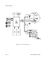
RDAG12-8 Block Diagram . . . . . . . . . . . . . . . . . . . . . . . . . . . . . . . . . . . .
RDAG12-8 Hole Spacing Diagram . . . . . . . . . . . . . . . . . . . . . . . . . . . . . .
Simplified Schematic for Voltage and Current Sink Outputs . . . . . . . . . .
Typical RS485 Two-Wire Multidrop Network . . . . . . . . . . . . . . . . . . . . . .
Page 1-6
Page 1-7
Page 2-9
Page A-3
List of Tables
Table 2-1: 50 Pin Connector Assignments . . . . . . . . . . . . . . . . . . . . . . . . . . . . . . . . .
Table 3-1: RDAG12-8 Command List . . . . . . . . . . . . . . . . . . . . . . . . . . . . . . . . . . . .
Table A-1: Connections Between Two RS422 Devices . . . . . . . . . . . . . . . . . . . . . . . .
Table A-2: RS422 Specification Summary . . . . . . . . . . . . . . . . . . . . . . . . . . . . . . . . .
Page 2-7
Page 3-2
Page A-1
Page A-2
Page v
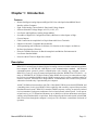
Chapter 1: Introduction
Features
•
•
•
•
•
•
•
•
•
•
Remote Intelligent Analog Output and Digital I/O Units with Opto-Isolated RS485 Serial
Interface to Host Computer
Eight 12-Bit Analog Current Sinks (4-20mA) and Voltage Outputs
Software Selectable Voltage Ranges of 0-5V, 0-10V, ±5V
Low-Power and High-Power Analog Output Models
Seven Bits of Digital I/O Configured on a Bit-by-Bit Basis as either Inputs or HighCurrent Outputs
Field Connections Accomplished via 50-pin Removable Screw Terminals
Onboard 16-bit 8031 Compatible Microcontroller
All Programming and Calibration in Software, No Switches to Set. Jumpers Available to
By-Pass Opto-Isolators if Desired
Protective NEMA4 Enclosure for Harsh Atmospheric and Marine Environments for
Low-Power Standard Model
Protective Metal T-Box for High-Power Model
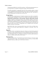
Description
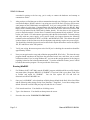
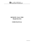
RDAG12-8 is an intelligent, 8-channel, digital-to-analog converter unit that communicates with the
host computer via EIA RS-485, Half-Duplex, serial communications standard. ASCII-based
command/response protocol permits communication with virtually any computer system.
RDAG12-8 is one of a series of remote intelligent Pods called the "REMOTE ACCES Series". As
many as 32 REMOTE ACCES Series Pods (or other RS485 devices) may be connected on a single
two or four-wire multidrop RS485 network. RS485 repeaters may be used to extend the number of
Pods on a network. Each unit has a unique address. Communication uses a master/slave protocol
wherein the Pod talks only if questioned by the computer.
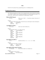
An 80C310 Dallas microcontroller (with 32k x 8 bits RAM, 32K bits non-volatile EEPROM, and
a watchdog timer circuit) gives RDAG12-8 the capability and versatility expected from a modern
distributed control system. RDAG12-8 contains CMOS low-power circuitry, an optically-isolated
receiver/transmitter, and power conditioners for local and external isolated power. It can operate
at baud rates up to 57.6 Kbaud and distances up to 4000 feet with low-attenuation twisted-pair
cabling, such as Belden #9841 or equivalent. Data collected by the Pod can be stored in local RAM
and accessed later through the computer's serial port. This facilitates a stand-alone Pod mode of
operation.
Manual MRDAG12-8H.Bc1
Page 1-1
RDAG12-8 Manual
All programming of RDAG12-8 is in ASCII-based software. ASCII-based programming permits you
to write applications in any high-level language that supports ASCII string functions.
The module, or Pod, address is programmable from 00 to FF hex and whatever address is assigned
is stored in EEPROM and used as the default address at the next Power-ON. Similarly, the baud rate
is programmable for 1200, 2400, 4800, 9600, 14400, 19200, 28800, and 57600. The baud rate is
stored in EEPROM and used as default at the next Power-ON.
Analog Outputs
These units consist of eight independent 12-bit digital-to-analog converters (DACs), and amplifiers
for voltage outputs and voltage-to-current conversion. The DACs may be updated in a channel-bychannel mode or simultaneously. There are eight channels of voltage output and eight
complimentary channels for 4-20mA current output sinks. The output voltage ranges are software
selectable. Calibration is performed by software. Factory calibration constants are stored in the
EEPROM memory and can be updated by disconnecting the I/O wiring and entering the software
calibration mode. Model RDAG12-8 can supply analog outputs of up to 5 mA on voltage ranges of
0-5V, ±5V, and 0-10V. By writing discrete values of a desired waveform into the buffers and
loading the buffers into the DAC at a programmable rate (31-6,000Hz) the units can generate
arbitrary waveforms or control signals.
Model RDAG12-8H is similar except that each DAC output can drive loads up to 250mA using a
±12V @ 2.5A local power supply. RDAG12-8H is packaged in a non-sealed “T-Box” steel
enclosure.
Digital I/O
Both models also have seven digital input/output ports. Each port can be individually programmed
as an input or an output. Digital input ports can accept logic high input voltages up to 50V and are
overvoltage protected to 200 VDC. Output drivers are open collector and can comply with up to 50
VDC of user-supplied voltage. Each output port can sink up to 350 mA but total sink current is
limited to a cumulative total of 650 mA for all seven bits.
Watchdog Timer
The built-in watchdog timer resets the Pod if the microcontroller "hangs up" or the power supply
voltage drops below 7.5 VDC. The microcontroller may also be reset by an external manual
pushbutton connected to /PBRST (pin 41 of the interface connector).
Page 1-2
Manual MRDAG12-8H.Bc1
Specifications
Serial Communications Interface
•
•
•
•
•
•
•
Serial Port:
Opto-isolated Matlabs type LTC491 Transmitter/Receiver. Compatible
with RS485 specification. Up to 32 drivers and receivers allowed on the
line. I/O bus programmable from 00 to FF hex (0 to 255 decimal).
Whatever address is assigned is stored in EEPROM and used as default
at next Power-On.
Asynchronous Data Format:
7 data bits, even parity, one stop bit.
Input Common Mode Voltage: 300V minimum (opto-isolated). If opto-isolators are
by-passed: -7V to +12V.
Receiver Input Sensitivity:
±200 mV, differential input.
Receiver Input Impedance:
12KΩ minimum.
Transmitter Output Drive:
60 mA, 100 mA short circuit current capability.
Serial Data Rates:
Programmable for 1200, 2400, 4800, 9600, 14400, 19200,
28800, and 57600 baud. Crystal oscillator provided.
Analog Outputs
•
•
•
•
•
•
•
•
•
Channels:
Type:
Non-Linearity:
Monotonicity:
Output Range:
Output Drive:
Current Output:
Output Resistance:
Settling Time:
Eight independent.
12-bit, double-buffered.
±0.9 LSB maximum.
±½ bit.
0-5V, ±5V, 0-10V.
Low Power Option: 5 mA, High Power Option: 250 mA.
4-20 mA SINK (User supplied excitation of 5.5V-30V).
0.5.
15 µsec to ±½ LSB.
Digital I/O
•
•
•
Seven bits configured as input or output.
Digital Inputs Logic High:
+2.0V to +5.0V at 20µA max. (5mA max at 50V in)
Protected to 200 VDC
Logic Low:
-0.5V to +0.8V at 0.4 mA max. Protected to -140 VDC.
Digital Outputs Logic-Low
Sink Current: 350 mA maximum. (See note below.)
Inductive kick suppression diode included in each circuit.
Note
Maximum allowable current per output bit is 350 mA. When all seven bits are used, there is a
maximum total current of 650 mA.
•
High-Level Output Voltage:
Manual MRDAG12-8H.Bc1
Open Collector, compliance with up to 50VDC
user-supplied voltage. If no user supplied voltage exists,
outputs pulled up to +5VDC via 10 kΩ resistors.
Page 1-3
RDAG12-8 Manual
Interrupt Input (For use with development kit)
•
•
•
Input Low:
-0.3V to +0.8V.
Input Low Current at 0.45V: -55µA.
Input High:
2.0V to 5.0V.
Environmental
The environmental characteristics depend on the RDAG12-8 configuration.
Low and High power output configurations:
• Operating Temperature Range: 0 EC. to 65 EC. (Optional -40 EC. to +80 EC.).
• Temperature De-rating:
Based on the power applied, maximum operating
temperature may have to be de-rated because internal
power regulators dissipate some heat. For example,
when 7.5VDC is applied, the temperature rise inside the
enclosure is 7.3EC above the ambient temperature.
Note
Maximum operating temperature can be determined according to the following equation:
VI(TJ = 120) < 22.5 - 0.2TA
Where TA is the ambient temperature in EC. and VI(TJ = 120) is the voltage at which the integral voltage
regulator junction temperature will rise to a temperature of 120 EC.
(Note: The junction temperature is rated to 150 EC. maximum.)
For example, at an ambient temperature of 25 EC., the voltage VI can be up to 17.5V.
At an ambient temperature of 100 EF. (37.8 EC.), the voltage VI can be up to 14.9V.
•
•
Humidity:
Size:
Page 1-4
5% to 95% RH non-condensing.
NEMA-4 Enclosure 4.53" long by 3.54" wide by 2.17"
high.
Manual MRDAG12-8H.Bc1
Power Required
Power can be applied from the computer's +12VDC power supply for the opto-isolated section
via the serial communication cable and from a local power supply for the rest of the unit. If you do not
wish to use power from the computer, a separate power supply isolated from the local power supply may
be used for the opto-isolated section. The power used by this section is minimal (less than 0.5W).
Low power version:
• Local Power:
+12 to 18 VDC @ 200 mA. (See box that follows.)
• Opto-Isolated Section: 7.5 to 25 VDC @ 40 mA. (Note: Due to the small amount of
current required, voltage drop in long cables is not significant.)
High power version:
• Local Power:
•
+12 to 18 VDC at up to 2 ½ A, and -12 to 18V at 2A depending
on the output load drawn.
Opto-Isolated Section: 7.5 to 25 VDC @ 50 mA. (Note: Due to the small amount of
current required, voltage drop in long cables is not significant.)
Note
If the local power supply has an output voltage greater than 18VDC, you can install a Zener diode
in series with the supply voltage. The voltage rating of the Zener diode (VZ) should be equal to
VI-18 where VI is the power supply voltage. The power rating of the Zener diode should be $
VZx0.12 (watts). Thus, for example, a 26VDC power supply would require using an 8.2V Zener
diode with a power rating of 8.2 x 0.12 . 1 watt.
Manual MRDAG12-8H.Bc1
Page 1-5
RDAG12-8 Manual
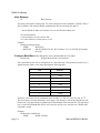
Figure 1-1: RDAG12-8 Block Diagram
Page 1-6
Manual MRDAG12-8H.Bc1
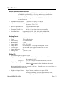
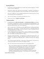
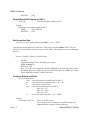
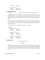
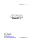
Figure 1-2: RDAG12-8 Hole Spacing Diagram
Manual MRDAG12-8H.Bc1
Page 1-7
Chapter 2: Installation
The software provided with this card is contained on CD and must be installed onto your hard disk
prior to use. To do this, perform the following steps applicable for your operating system. Substitute
the appropriate drive letter for your CD-ROM where you see d: in the examples below.
CD Installation
WIN95/98/NT/2000
a.
Place the CD into your CD-ROM drive.
b.
The install program should automatically run after 30 seconds. If the install program does
not run, click START | RUN and type d:install, click OK or press K.
c.
Follow the on-screen prompts to install the software for this card.
Directories Created on the Hard Disk
The installation process will create several directories on your hard disk. If you accept the
installation defaults, the following structure will exist.
[CARDNAME]
Root or base directory containing the SETUP.EXE setup program used to help you configure
jumpers and calibrate the card.
DOS\PSAMPLES:
DOS\CSAMPLES:
Win32\language:
A subdirectory of [CARDNAME] that contains Pascal samples.
A subdirectory of [CARDNAME] that contains "C" samples.
Subdirectories containing samples for Win95/98 and NT.
WinRISC.exe
A Windows dumb-terminal type communication program designed for RS422/485 operation.
Used primarily with Remote Data Acquisition Pods and our RS422/485 serial communication
product line. Can be used to say hello to an installed modem.
ACCES32
This directory contains the Windows 95/98/NT driver used to provide access to the hardware
registers when writing 32-bit Windows software. Several samples are provided in a variety of
languages to demonstrate how to use this driver. The DLL provides four functions (InPortB,
OutPortB, InPort, and OutPort) to access the hardware.
This directory also contains the device driver for Windows NT, ACCESNT.SYS. This device driver
provides register-level hardware access in Windows NT. Two methods of using the driver are
available, through ACCES32.DLL (recommended) and through the DeviceIOControl handles
provided by ACCESNT.SYS (slightly faster).
Manual MRDAG12-8H.Bc1
Page 2-1
RDAG12-8 Manual
SAMPLES
Samples for using ACCES32.DLL are provided in this directory. Using this DLL not only
makes the hardware programming easier (MUCH easier), but also one source file can be used
for both Windows 95/98 and WindowsNT. One executable can run under both operating
systems and still have full access to the hardware registers. The DLL is used exactly like any
other DLL, so it is compatible with any language capable of using 32-bit DLLs. Consult the
manuals provided with your language's compiler for information on using DLLs in your specific
environment.
VBACCES
This directory contains sixteen-bit DLL drivers for use with VisualBASIC 3.0 and Windows 3.1
only. These drivers provide four functions, similar to the ACCES32.DLL. However, this DLL is
only compatible with 16-bit executables. Migration from 16-bit to 32-bit is simplified because of
the similarity between VBACCES and ACCES32.
PCI
This directory contains PCI-bus specific programs and information. If you are not using a PCI card,
this directory will not be installed.
SOURCE
A utility program is provided with source code you can use to determine allocated resources at
run-time from your own programs in DOS.
PCIFind.exe
A utility for DOS and Windows to determine what base addresses and IRQs are allocated to
installed PCI cards. This program runs two versions, depending on the operating system. Windows
95/98/NT displays a GUI interface, and modifies the registry. When run from DOS or Windows3.x,
a text interface is used. For information about the format of the registry key, consult the
card-specific samples provided with the hardware. In Windows NT, NTioPCI.SYS runs each time
the computer is booted, thereby refreshing the registry as PCI hardware is added or removed. In
Windows 95/98/NT PCIFind.EXE places itself in the boot-sequence of the OS to refresh the registry
on each power-up.
This program also provides some COM configuration when used with PCI COM ports. Specifically,
it will configure compatible COM cards for IRQ sharing and multiple port issues.
WIN32IRQ
This directory provides a generic interface for IRQ handling in Windows 95/98/NT. Source code
is provided for the driver, greatly simplifying the creation of custom drivers for specific needs.
Samples are provided to demonstrate the use of the generic driver. Note that the use of IRQs in
near-real-time data acquisition programs requires multi-threaded application programming
techniques and must be considered an intermediate to advanced programming topic. Delphi, C++
Builder, and Visual C++ samples are provided.
Page 2-2
Manual MRDAG12-8H.Bc1
Findbase.exe
DOS utility to determine an available base address for ISA bus , non-Plug-n-Play cards. Run this
program once, before the hardware is installed in the computer, to determine an available address
to give the card. Once the address has been determined, run the setup program provided with the
hardware to see instructions on setting the address switch and various option selections.
Poly.exe
A generic utility to convert a table of data into an nth order polynomial. Useful for calculating
linearization polynomial coefficients for thermocouples and other non-linear sensors.
Risc.bat
A batch file demonstrating the command line parameters of RISCTerm.exe.
RISCTerm.exe
A dumb-terminal type communication program designed for RS422/485 operation. Used primarily
with Remote Data Acquisition Pods and our RS422/485 serial communication product line. Can be
used to say hello to an installed modem. RISCTerm stands for Really Incredibly Simple
Communications TERMinal.
Getting Started
To begin working with the pod, you first need an available working serial communications port on
your PC. This can be either one of our RS422/485 Serial Communication cards or an existing RS232 port with a 232/485 two-wire converter attached. Next, install the software from the 3½" diskette
(RDAG12-8 Software Package). You should also run the RDAG12-8 setup program (which is on
the 3½" diskette) to help you with option selection.
1.
Verify that you are able to communicate through the COM port (see details in the appropriate COM
card manual). View Control Panel | Ports (NT 4) or Control Panel | System | Device Manager | Ports
| Properties | Resources (9x/NT 2000) for information about installed COM ports. Communication
verification can be done by using a loop-back connector with the card in full-duplex RS-422 mode.
A working knowledge of serial ports in Windows will significantly contribute to your success. You
may have built-in COM ports 1 & 2 on your Motherboard, but the software necessary to support
them may not be installed in your system. From the Control Panel you may need to “add new
hardware” and select standard serial communication port to add a COM port to your system. You
may also need to check in the BIOS to ensure that the two standard serial ports are enabled.
We provide two terminal programs to aid with this task. RISCTerm is a DOS-based terminal
program, which can also be used in Windows 3.x and 9x. For Windows 9x/NT 4/NT 2000, you can
use our WinRISC program. You can select the COM port number (COM5, COM8, etc.), baud, data
bits, parity, and stop bits. ACCES Pods ship at 9600, 7, E, 1, respectively. The simplest test to see
if you have a good COM port without connecting anything to the COM Port connector on the back
of your computer is to select either COM 1 or COM 2 (whichever one is showing up in your device
manager) from WinRISC (See “Running WinRISC”) then clicking on “Connect”. If you don’t get
an error, that is a very good sign that you’re in business. Click the checkbox called “local echo”,
then click into the text window, where you should see the blinking cursor, and start typing. If you’ve
Manual MRDAG12-8H.Bc1
Page 2-3
RDAG12-8 Manual
succeeded in getting to the last step, you’re ready to connect the hardware and attempt to
communicate with it.
2.
After you have verified that you are able to communicate through your COM port, set up your COM
card for half-duplex, RS-485, and wire it up using two wires to the Pod. (You may need to move
some jumpers on the COM board to accomplish this. Or if you’re using our RS-232/485 Converter,
please connect it at this time. Communication with the Pod should be two-wire RS-485, HalfDuplex with Termination and Bias applied. Also select No Echo (where Echo exists) on the COM
card. See your manual for the COM card for further details.) You also have to wire appropriate
power to the Pod terminals. See the Screw Terminal Pin assignments for help with this. For best
results, you’ll need +12V and a return to power the pod in the non-isolated mode. For bench testing
and setup with one power supply, you’ll need to install wire jumpers between the following
terminals on the terminal block: ISOV+ to PWR+, and ISOGND to GND. This defeats the optical
isolation feature of the Pod, but eases the development setup and only requires one power supply.
You should also check the processor board as described in Option Selection to ensure the jumpers
JP2, JP3 and JP4 are in the /ISO position.
3.
Verify your wiring, then turn on power to the Pod. If you’re checking, the current draw should be
approximately 250mA.
4.
Now you can again run the setup and calibration program(DOS, Win3.x/9x). This time the setup
program should auto-detect the Pod from the auto-detect menu item, and allow you to run the
calibration routine. If you’re using Windows NT, you can run the setup program to set the jumpers
regarding isolated or non-isolated communication. To run the calibration routine, just use a DOS
boot disk, then run the program. We can provide this if necessary.
Running WinRISC
1.
For Windows 9x/NT 4/NT 2000, start the WinRISC program, which should be accessible from the
start menu (Start | Programs | RDAG12-8 | WinRISC). If you can’t find it, go to Start | Find | Files
or Folders and search for WinRISC.
You can also explore the CD and look for
disks\tools.win\Win32\WinRISC.exe.
2.
Once you’re in WinRISC, select a baud rate of 9600 (factory default for the Pod). Select Local Echo
and the following other settings: Parity-Even, Data Bits-7, Stop Bits-1. Leave other settings at the
default. Select the verified COM port (top left) and click on “Connect”.
3.
Click into the main box. You should see a blinking cursor.
4.
Type a few characters. You should see them print to the screen.
5.
Proceed to the section “TALKING TO THE POD”.
Page 2-4
Manual MRDAG12-8H.Bc1
Running RISCterm
1.
For Win 95/98, run the program RISCTerm.exe found in Start | Programs | RDAG12-8. For DOS
or Win 3.x, look in C:\RDAG12-8.
2.
Enter the base address of the COM card, then enter the IRQ. In Windows, this information is
available by viewing the ControlPanel | System | DeviceManager | Ports | Properties | Resources.
3.
Once you’re in RISCTerm, verify a selection of 9600 baud (factory default for the Pod). The bar
across the bottom of the screen should say 7E1.
4.
Type a few letter characters. You should see them print to the screen.
5.
Proceed to the section, “TALKING TO THE POD”.
Talking to the Pod
1.
(Picking up from step 5 of “RUNNING WINRISC” or “RUNNING RISCTERM”) Press the Enter
key a few times. You should receive, “Error, use ? for command list, unrecognized command:” This
is your first indication that you’re talking to the Pod. Repeatedly pressing the Enter key should
return this message each time. This is a correct indication.
2.
Type “?” and press enter. You should receive back “Main Help Screen” and three possible other
menus to access. You could type “?3" then press Enter, and receive a menu back from the Pod
regarding Analog Output Commands. If you’re receiving these messages, you again know that you
are communicating effectively with the Pod.
3.
Connect a DMM, set for 20VDC range, across pins 1 (+) and 2 (-) of the Pod’s screw terminal block.
Type “AC0=0000,00,00,01,0000" and [Enter]. You should receive a CR (carriage return) from the
Pod. This command sets Channel 0 for the 0-10V range.
4.
Now type “A0=FFF0" and [Enter]. You should receive a carriage return from the Pod. This
command causes Channel 0 to output the commanded value (FFF in hex = 4096 counts, or 12-bit,
Full Scale). You should see the DMM read 10VDC. Calibration is discussed in the following
section.
5.
Type “A0=8000” and [Enter] (800 in hex = 2048 counts, or 12-bit, Half Scale). You should receive
a carriage return from the Pod. You should see the DMM read 5VDC.
6.
You’re now ready to begin your development and write your application program.
Note: If you’re ultimately going to use the “Isolated Mode”, be sure that you put the
jumpers on the processor board back to the “ISO” positions. Also ensure that you
wire the power up correctly to support that mode. It requires 12V of local power,
and 12V of isolated power. Isolated Power can be supplied from the computer’s
power supply, or some other central supply. Current draw on this source is
negligible, so voltage drop in the cable is of no consequence. Be aware that the High
Power Pod version (RDAG12-8H) requires +12V, Gnd, and -12V for “Local Power”.
Manual MRDAG12-8H.Bc1
Page 2-5
RDAG12-8 Manual
Calibration
The setup software provided with the RDAG12-8 and RDAG12-8H supports the ability to check
calibration and to write correction values into EEPROM so they are available automatically on
power-up. Calibration checks need only be performed periodically, not every time power is cycled.
The SETUP.EXE software calibration procedure can be used to calibrate all three ranges and store
the values in the EEPROM. For Windows NT, you’ll need to boot to DOS to run this program. You
can create a DOS boot disk from any Windows system not running NT. We can provide a DOS boot
disk if necessary.
The SAMPLE1 program illustrates the procedure of recalling these values and adjusting the
readings. The description of the CALn? command shows the order in which the information is
stored in the EEPROM.
Installation
The RDAG12-8 enclosure is a sealed, die-cast, aluminum-alloy, NEMA-4 enclosure that is easily
mounted. Outside dimensions of the enclosure are: 8.75" long by 5.75" wide by 2.25" high. The
cover incorporates a recessed neoprene gasket and the cover is secured to the body by four recessed
M-4, stainless steel, captive screws. Two long M-3.5 X 0.236 screws are provided for mounting to
the body. Mounting holes and cover-attaching screws are outside the sealed area to prevent ingress
of moisture and dust. Four threaded bosses inside the enclosure provide for mounting the printed
circuit card assemblies. To install the card without the box in your own enclosure, see Figure 1-2
for the hole spacing.
The RDAG12-8H enclosure is a non-sealed steel enclosure painted “IBM Industrial Gray”. The
enclosure measures 8.5" long by 5.25" wide by 2" high.
There are three jumper locations on the unit and their functions are as follows:
JP2, JP3, and JP4: Normally these jumpers should be in the "ISL" position. If you wish to
by-pass the opto-isolators, then you can move these jumpers to the "/ISL"
position.
Input/Output Pin Connections
Electrical connections to the RDAG12-8 are through a watertight gland that seals the wires and are
terminated inside to a Euro style, screw-terminal block that plugs into a 50-pin connector. Electrical
connections to the RDAG12-8H are through openings on the end of the T-Box, terminated in the
same Euro style, screw-terminal block. Connector pin assignments for the 50-pin connector follow:
Page 2-6
Manual MRDAG12-8H.Bc1
Pin
1
3
5
7
9
11
13
15
17
19
21
23
25
27
29
31
33
35
37
39
41
43
45
47
49
Signal
(Analog Volt. Output 0)
(Analog Volt. Output 1)
(Analog Volt. Output 2)
(Local Power Ground)
VOUT0
VOUT1
VOUT2
GND
DIO5
DIO3
DIO1
GND
VOUT3
IOUT1
IOUT3
IOUT4
IOUT6
AOGND
VOUT4
GND
/PINT0
PWR+
GND
VOUT5
/PBRST
ISOV+
/RS485VOUT6
VOUT7
(Digital Input/Output 5)
(Digital Input/Output 3)
(Digital Input/Output 1)
(Local Power Ground)
(Analog Volt. Output 3)
(Analog Current Output 1)
(Analog Current Output 3)
(Analog Current Output 4)
(Analog Current Output 6)
(Analog Output Ground)
(Analog Volt. Output 4)
(Local Power Ground)
(Protected Interr. Input 0)
(Local Power Supply +)
(Local Power Ground)
(Analog Volt. Output 5)
(Pushbutton Reset)
(Isol. Power Supply +)
(Communication Port -)
(Analog Volt. Output 6)
(Analog Volt. Output 7)
Pin
2
4
6
8
10
12
14
16
18
20
22
24
26
28
30
32
34
36
38
40
42
44
46
48
50
Signal
APG0
(Analog Power Ground 0)
APG1
(Analog Power Ground 1)
APG2
(Analog Power Ground 2)
DIO6
(Digital Input/Output 6)
DIO4
(Digital Input/Output 4)
DIO2
(Digital Input/Output 2)
DIO0
(Digital Input/Output 0)
APG3
(Analog Power Ground 3)
IOUT0
(Analog Current Output 0)
IOUT2
(Analog Current Output 2)
AOGND
(Analog Output Ground)
IOUT5
(Analog Current Output 5)
IOUT7
(Analog Current Output 7)
APG4
(Analog Power Ground 4)
AOGND
(Analog Output Ground)
/PINT1
(Protected Interr. Input 1)
/PT0
(Protected Tmr./Ctr. Input)
PWR+
(Local Power Supply +)
APG5
(Analog Power Ground 5)
PWR(Local Power Supply -)
ISOGND
(Isol. Power Supply)
RS485+
(Communication Port +)
APG6
(Analog Power Ground 6)
APPLV+ (Application Power Ground 7)
APG7
(Analog Power Ground 7)
Table 2-1: 50 Pin Connector Assignments
Terminal markings and their functions are as follows:
PWR+ and GND:
(Pins 7, 15, 31, 35, and 37) These terminals are used to apply local power
to the Pod from a local power supply. (Pins 35 and 36 are tied together.)
The voltage can be anywhere in the range of 12 VDC to 16 VDC. Higher
voltage can be used, 24 VDC for example, if an external Zener diode is
used to reduce the voltage applied to the RDAG12-8. (See the
Specification section of this manual to determine the Zener diode power
rating required.)
PWR-
(Pin 40) This terminal accepts customer supplied -12V to 18 VDC @ 2A
max. It is used only in the High Power option RDAG12-8H.
Manual MRDAG12-8H.Bc1
Page 2-7
RDAG12-8 Manual
ISOV+ and ISOGND: This is the power connection for the isolator section that may be supplied
from the computer's +12VDC supply via a pair of wires on the RS-485
network or from a central power supply. This power is independent of
"local power". The voltage level can be from 7.5 VDC to 35 VDC. (An
on-board voltage regulator regulates the power to +5 VDC.) RDAG12-8
will require only about 5 mA of current when idling and ~33mA current
when data is being transmitted so any loading effects on the computer
power (if used) will be low.
Note
If separate power is not available, ISOV+ and ISOGND must be jumpered to the "local power"
terminals, which defeats the optical isolation.
RS485+ and RS485-:
These are the terminals for RS485 communications (TRx+ and TRx-).
APPLV+:
This terminal is for the "application power" or the user provided voltage
source to which digital outputs are connected through the loads.
Open-collector Darlington amplifiers are used at the outputs. Inductive
suppression diodes are included in the APPLV+ circuit. The application
power level (APPLV+) can be as high as 50 VDC.
APG0-7:
These terminals are for use with the High Power version of the Pod
(RDAG12-8H). Connect all load returns to these terminals.
AOGND:
These terminals are for use with the Low Power version of the Pod. Use
these for returns of voltage outputs as well as current outputs.
GND:
These are general purpose grounds which can be used for Digital Bit
returns, Power return connections, and so on.
To ensure that there is minimum susceptibility to EMI and minimum radiation, it is important that
there be a positive chassis ground. Also, proper EMI cabling techniques (cable connected to chassis
ground, twisted pair wiring, and, in extreme cases, ferrite-level of EMI protection) may be needed
for input/output wiring.
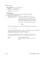
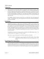
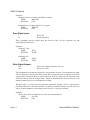
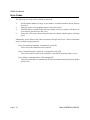
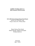
VOUT0-7:
Analog Output Voltage signal, use in conjunction with AOGND
IOUT0-7:
4-20mA Current Sink Output signal, use in conjunction with an external
power supply (5.5V to 30V).
Page 2-8
Manual MRDAG12-8H.Bc1
Figure 2-1: Simplified Schematic for Voltage and Current Sink Outputs
Manual MRDAG12-8H.Bc1
Page 2-9
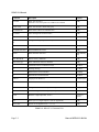
Chapter 3: Software
General
The RDAG12-8 comes with ASCII-based software provided on CD. ASCII programming permits
you to write applications in any high-level language that supports ASCII text string functions,
allowing the "REMOTE ACCES" series modules to be used with virtually any computer that has an
RS485 port.
The communication protocol has two forms: addressed and non-addressed. Non-addressed protocol
is used when only one REMOTE ACCES Pod is to be used. Addressed protocol must be used when
more than one REMOTE ACCES Pod is to be used. The difference is that an address command is
sent to enable the specific Pod. The address command is only sent once during communication
between the specific Pod and the host computer. It enables communication with that specific Pod
and disables all other REMOTE ACCES devices on the network.
Command Structure
All communication must be 7 data bits, even parity, 1 stop bit. All numbers sent to and received from
the Pod are in hexadecimal form. The factory default baud rate is 9600 Baud. The Pod is considered
to be in addressed mode any time its Pod address is not 00. The factory default Pod address is 00
(non-addressed mode).
Addressed Mode
The address select command must be issued before any other command to the addressed Pod. The
address command is as follows:
"!xx[CR]" where xx is the Pod address from 01 to FF hex, and [CR] is Carriage Return, ASCII
character 13.
The Pod responds with "[CR]". Once the address select command has been issued, all further
commands (other than a new address select) will be executed by the selected Pod. The addressed
mode is required when using more than one Pod. When there's only one Pod connected, no address
select command is needed.
You can merely issue commands listed in the following table. Terminology used is as follows:
a.
b.
c.
d.
e.
f.
General Note:
The single lower case letter 'x' designates any valid hex digit (0-F).
The single lower case letter 'b' designates either a '1' or '0'.
The symbol '±' designates either a '+' or a '-'.
All commands are terminated with [CR], the ASCII character 13.
All commands are not case-sensitive, i.e., upper or lower case may be used.
The symbol '*' means zero or more valid characters (total msg length<255 decimal).
ALL numbers passed to and from the Pod are in hexadecimal.
Manual MRDAG12-8H.Bc1
Page 3-1
RDAG12-8 Manual
Command
Description
Returns
An=xxx0
Write xxx0 to DAC n
If the letter A is sent in place of n, all DACs are affected
[CR]
An,iiii=xxx0
Write xxx0 to DAC n buffer entry [iiii]
[CR]
An=GOGOGO
Write buffer to DAC n at Timebase rate
[CR]
An=STOP
Cease writing DAC n buffer to DAC
[CR]
S=xxxx or S?
Set or read acquisition rate (00A3 <= xxxx <= FFFF)
(xxxx)[CR]
ACn=xxx0,dd,tt,mm,
iiii
Configure Analog Outputs. See body text.
[CR]
BACKUP=BUFFER
Write buffer into EEPROM
[CR]
BUFFER=BACKUP
Read EEPROM into buffer
[CR]
CALn?
Read calibration data for n
bbbb,mmmm[
CR]
CAL=BACKUP
Restore factory calibration
[CR]
Caln=xxxx,yyyy
Write calibration values for channel n
[CR]
?
Command reference for RDAG12-8(H)
See Desc.
H
Greeting message
See Desc.
V
Read firmware revision number
n.nn[CR]
N
Resend Pod’s last transmission
See Desc.
POD=xx
Assign pod to number xx
-:Pod#xx[CR]
BAUD=nnn
Set communication baud rate (1 <= n <= 7)
=:Baud:0n[CR
]
Mxx
Set digital mask to xx, 1 is output, 0 is input
[CR]
Mx+ or Mx-
Set bit x of digital mask to output (+) or input (-)
[CR]
I or In
Read the 7 digital input bits, or bit n
xx[CR] or
b[CR]
Oxx
Write byte xx to digital outputs (7 bits are significant)
[CR]
On+ or On-
Turn on or off digital bit n (0 <= n <= 6)
[CR]
Table 3-1: RDAG12-8 Command List
Page 3-2
Manual MRDAG12-8H.Bc1
Note
Pod reset occurs upon power-up, programming process, or watchdog time-out.
Command Functions
The following paragraphs give details of the command functions, describe what the commands
cause, and give examples. Please note that all commands have an acknowledgement response. You
must wait for a response from a command before sending another command.
Write to DAC Channel
An=xxx0
Writes xxx to DAC n. Set polarity and gain using the AC
command.
Example:
Program the Analog output number 4 to half-scale (zero volts bipolar or half scale unipolar)
SEND:
A4=8000[CR]
RECEIVE:
[CR]
Load Buffer for DAC n
An,iiii=xxx0
Writes xxx to DAC n buffer [iiii].
Example:
Program buffer for DAC 1 to a simple stair step
SEND:
A1,0000=0000[CR]
RECEIVE:
[CR]
SEND:
A1,0001=8000[CR]
RECEIVE:
[CR]
SEND:
A1,0002=FFF0[CR]
RECEIVE:
[CR]
SEND:
A1,0003=8000[CR]
RECEIVE:
[CR]
Read Buffer from DAC n
An,iii=?
Reads from buffer (0 <= n <= 7, 0 <= iiii <= 800h).
Example:
Read buffer entry number 2 for DAC 1
SEND:
A1,0002=?[CR]
RECEIVE:
FFF0[CR]
Start Buffered DAC Output on DAC n
An=GOGOGO
Writes buffer to DAC n at a timebase rate.
Example:
Begin Buffer writing on DAC 5
SEND:
A5=GOGOGO[CR]
Manual MRDAG12-8H.Bc1
Page 3-3
RDAG12-8 Manual
RECEIVE:
[CR]
Stop Buffered DAC Outputs on DAC n
An=STOP
Ceases writing DAC n buffer to DAC.
Example:
Immediately cease pattern output on DAC 5
SEND:
A5=STOP[CR]
RECEIVE:
[CR]
Set Acquisition Rate
S=xxxx or s=? Set or read acquisition rate (0100 <= xxxx <= FFFF).
This function sets the update rate of the DAC. Valid values range from 0100 to FFFF. The value
passed is the desired divisor of the rate clock (11.0592 MHz). The equation to use in calculating the
divisor is:
Divisor = [Clock/12] / [Rate], or 921000 / Rate
Example:
Program the RDAG12-8 for 1K samples per second
SEND: S=0399[CR]
RECEIVE: [CR]
Note: The sample rate configured is stored in EEPROM on the Pod, and will be used as
the default (power-on) sample rate. The factory default sample rate (100Hz, or S=2400)
can be restored by sending “S=0000” to the Pod.
Configure Buffers and DACs
ACn=xxx0,dd,tt,mm,iiii
xxx0 is the desired power-on (initial) state of DAC n
dd
is the divisor for the output rate (00 <= dd <= FF)
tt
is the number of times to run
mm
is the polarity and gain select for DAC n
mm = 00 = ±5V
mm = 01 = 0-10V
mm = 02 = 0-5V
iiii
is the buffer array entry (000 <= iiii <= 800h)
Example:
To configure DAC 3 to:
Page 3-4
Power on at 8000 counts;
Use one half the Sxxxx timebase as its buffered output rate;
Output the Buffer a total of 15 times, then stop;
Manual MRDAG12-8H.Bc1
Use the ±5V range;
Output a buffer a total of 800 hex entries long
Use the command:
AC3=8000,02,0F,00,0800[CR]
Set Calibration Parameters
CALn=bbbb,mmmm
Write span and offset calibration values in two’s-complement hex
as two four-digit numbers.
Example:
Write a span of 42h and an offset of 36h to DAC 1
SEND:
CAL1=0036,0042[CR]
RECEIVE:
[CR]
Read Calibration Parameters
CALn?
Recalls the scale and offset calibration constants.
Example:
Read calibration parameters after the above write
SEND:
CAL1?[CR]
RECEIVE:
0036,0042[CR]
Store Calibration Parameters
BACKUP=CAL
Backup the last calibration
This function stores the values required to adjust the measurement readings to agree with the last
calibration. The setup program will measure and write these calibration parameters. The
SAMPLE1 program illustrates using the CALn? Command with the results of this function.
Configure Bits as Input or Output
Mxx
Mx+
Mx-
Configures digital bits as inputs or outputs.
Configures digital bit 'x' as output.
Configures digital bit 'x' as input.
These commands program the digital bits, on a bit-by-bit basis, as input or output. A "zero" in any
bit position of the xx control byte designates the corresponding bit to be configured as an input.
Conversely, a "one" designates a bit to be configured as an output. (Note: Any bit configured as an
output can still be read as an input if the current value output is a "one".)
Manual MRDAG12-8H.Bc1
Page 3-5
RDAG12-8 Manual
Examples:
Program even bits as outputs, and odd bits as inputs.
SEND:
MAA[CR]
RECEIVE:
[CR]
Program bits 0-3 as input, and bits 4-7 as output.
SEND:
MF0[CR]
RECEIVE:
[CR]
Read Digital Inputs
I
In
Read 7 bits
Read bit number n
These commands read the digital input bits from the Pod. All byte responses are sent
most-significant nibble first.
Examples:
Read ALL 7 bits.
SEND:
RECEIVE:
Read only bit 2.
SEND:
RECEIVE:
I[CR]
FF[CR]
I2[CR]
1[CR]
Write Digital Outputs
Oxx
Ox±
Write to all 7 digital output bits. (Port 0)
Set bit x hi or low
These commands write outputs to digital bits. Any attempt to write to a bit configured as an input
will fail. Writing to a byte or word wherein some bits are input and some are output will cause the
output latches to change to the new value, but the bits which are inputs will not output the value
until/unless they are placed in output mode. Single bit commands will return an error (4) if an
attempt is made to write to a bit configured as an input.
Writing a "one" (+) to a bit asserts the pull-down for that bit. Writing a "zero" (-) de-asserts the
pull-down. Therefore, if the factory default +5V pull-up is installed, writing a one will cause zero
volts to be at the connector, and writing a zero will cause +5 volts to be asserted.
Examples:
Write a one to bit 6 (set output to zero volts, assert the pull-down).
SEND:
O6+[CR]
RECEIVE:
[CR]
Page 3-6
Manual MRDAG12-8H.Bc1
Write a zero to bit 2 (set output to +5V or user pull-up).
SEND:
O2-[CR]
or
SEND:
O02-[CR]
RECEIVE:
[CR]
Write zeros to bits 0-7.
SEND:
O00[CR]
RECEIVE:
[CR]
Write zeros to every odd bit.
SEND:
OAA[CR]
RECEIVE:
[CR]
Read Firmware Revision Number
V:
Read the firmware revision number
This command is used to read the version of firmware installed in the Pod. It returns "X.XX[CR]".
Example:
Read the RDAG12-8 version number.
SEND:
V[CR]
RECEIVE:
1.00[CR]
Note
The "H" command returns the version number along with other information. See "Hello Message"
following.
Resend Last Response
n
Resend last response
This command will cause the Pod to return the same thing it just sent. This command works for all
responses less than 255 characters in length. Normally this command is used if the host detected a
parity or other line fault while receiving data, and needs the data to be sent a second time.
The "n" command may be repeated.
Example:
Assuming the last command was "I", ask Pod to resend last response.
SEND:
n
RECEIVE:
FF[CR]
;or whatever the data was
Manual MRDAG12-8H.Bc1
Page 3-7
RDAG12-8 Manual
Hello Message
H*
Hello message
Any string of characters starting with "H" will be interpreted as this command. ("H[CR]" alone is
also acceptable.) The return from this command takes the form (without the quotes):
"=Pod aa, RDAG12-8 Rev rr Firmware Ver:x.xx ACCES I/O Products, Inc."
aa is the Pod address
rr is the hardware revision, such as "B1"
x.xx is the software revision, such as "1.00"
Example:
Read the greeting message.
SEND:
Hello?[CR]
RECEIVE:
Pod 00, RDAG12-8 Rev B1 Firmware Ver:1.00 ACCES I/O Products,
Inc.[CR]
Configure Baud Rate (When Shipped by Acces, the Baud Rate Is Set at 9600.)
BAUD=nnn
Program the Pod with a new baud rate
This command sets the Pod to communicate at a new baud rate. The parameter passed, nnn, is
slightly unusual. Each n is the same digit from the following table:
Code
Baud Rate
0
1200
1
2400
2
4800
3
9600
4
14400
5
19200
6
28800
7
57600
Therefore, valid values for the command's "nnn" are 000, 111, 222, 333, 444, 555, 666, or 777.
The Pod returns a message indicating it will comply. The message is sent in the old baud rate, not
the new one. Once the message is transmitted, the Pod changes to the new baud rate. The new baud
rate is stored in EEPROM and will be used even after power-reset, until the next "BAUD=nnn"
command is issued.
Example:
Set the Pod to 19200 baud.
SEND:
BAUD=555[CR]
Page 3-8
Manual MRDAG12-8H.Bc1
RECEIVE:
Baud:05[CR]
Set the Pod to 9600 baud.
SEND:
BAUD=333[CR]
RECEIVE:
Baud:03[CR]
Configure Pod Address
POD=xx
Program the currently selected Pod to respond at address xx.
This command changes the Pod's address to xx. If the new address is 00, the Pod will be placed into
non-addressed mode. If the new address is not 00, the Pod will not respond to further
communications until a valid address command is issued. Hex numbers 00-FF are considered valid
addresses. The RS485 specification allows only 32 drops on the line, so some addresses may be
unused.
The new Pod address is saved in EEPROM and will be used even after power-down until the next
"Pod=xx" command is issued. Note that, if the new address is not 00 (i.e., the Pod is configured to
be in addressed mode), it is necessary to issue an address command to the Pod at the new address
before it will respond.
The Pod returns a message containing the Pod number as confirmation.
Example:
Set the Pod address to 01.
SEND:
Pod=01[CR]
RECEIVE:
=:Pod#01[CR]
Set the Pod address to F3.
SEND:
Pod=F3[CR]
RECEIVE:
=:Pod#F3[CR]
Take the Pod out of addressed mode.
SEND:
Pod=00[CR]
RECEIVE:
=:Pod#00[CR]
Address Select
!xx
Selects the Pod addressed 'xx'
Note
When using more than one Pod in a system, each Pod is configured with a unique address. This
command must be issued prior to any other commands to that particular Pod. This command needs
to be issued only once prior to executing any other commands. Once the address select command
has been issued, that Pod will respond to all other commands until a new address select command
is issued.
Manual MRDAG12-8H.Bc1
Page 3-9
RDAG12-8 Manual
Error Codes
The following error codes can be returned from the Pod:
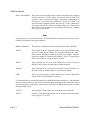
1:
3:
4:
9:
Invalid channel number (too large, or not a number. All channel numbers must be between
00 and 07).
Improper Syntax. (Not enough parameters is the usual culprit).
Channel number is invalid for this task (For example if you try to output to a bit that is set
as an input bit, that will cause this error).
Parity error. (This occurs when some part of the received data contains a parity or framing
error).
Additionally, several full-text error codes are returned. All begin with "Error, " and are useful when
using a terminal to program the Pod.
Error, Unrecognized Command: {command received}[CR]
This occurs if the command is not recognized.
Error, Command not fully recognized: {Command received}[CR]
This occurs if the first letter of the command is valid, but the remaining letters are not.
Error, Address command must be CR terminated[CR]
This occurs if the address command (!xx[CR]) has extra characters between the Pod number
and the [CR].
Page 3-10
Manual MRDAG12-8H.Bc1
Appendix A: Application Considerations
Introduction
Working with RS422 and RS485 devices is not much different from working with standard RS232
serial devices and these two standards overcome deficiencies in the RS232 standard. First, the cable
length between two RS232 devices must be short; less than 50 feet at 9600 baud. Second, many
RS232 errors are the result of noise induced on the cables. The RS422 standard permits cable lengths
up to 4000 feet and, because it operates in the differential mode, it is more immune to induced noise.
Connections between two RS422 devices (with CTS ignored) should be as follows:
Device #1
Device #2
Signal
Pin No.
Signal
Pin No.
Gnd
7
Gnd
7
TX
+
24
RX
+
12
-
13
-
25
RX
RX+
12
TX+
24
13
-
25
TX
RX
-
TX
Table A-1: Connections Between Two RS422 Devices
A third deficiency of RS232 is that more than two devices cannot share the same cable. This is also
true for RS422 but RS485 offers all the benefits of RS422 plus allows up to 32 devices to share the
same twisted pairs. An exception to the foregoing is that multiple RS422 devices can share a single
cable if only one will talk and the others will all receive.
Balanced Differential Signals
The reason that RS422 and RS485 devices can drive longer lines with more noise immunity than
RS232 devices is that a balanced differential drive method is used. In a balanced differential system,
the voltage produced by the driver appears across a pair of wires. A balanced line driver will produce
a differential voltage from ±2 to ±6 volts across its output terminals. A balanced line driver can also
have an input "enable" signal that connects the driver to its output terminals. If the "enable" signal
is OFF, the driver is disconnected from the transmission line. This disconnected or disabled
condition is usually referred to as the "tristate" condition and represents a high impedance. RS485
drivers must have this control capability. RS422 drivers may have this control but it is not always
required.
Manual MRDAG12-8H.Bc1
Page A-1
RDAG12-8 Manual
A balanced differential line receiver senses the voltage state of the transmission line across the two
signal input lines. If the differential input voltage is greater than +200 mV, the receiver will provide
a specific logic state on its output. If the differential voltage input is less than -200 mV, the receiver
will provide the opposite logic state on its output. A maximum operating voltage range is from +6V
to -6V allows for voltage attenuation that can occur on long transmission cables.
A maximum common mode voltage rating of ±7V provides good noise immunity from voltages
induced on the twisted pair lines. The signal ground line connection is necessary in order to keep the
common mode voltage within that range. The circuit may operate without the ground connection but
may not be reliable.
Parameter
Conditions
Driver Output Voltage (unloaded)
Driver Output Voltage (loaded)
Min.
Max.
4V
6V
-4V
-6V
LD and LDGND
2V
jumpers in
-2V
Driver Output Resistance
50Ω
Driver Output Short-Circuit Current
±150 mA
Driver Output Rise Time
10% unit interval
Receiver Sensitivity
±200 mV
Receiver Common Mode Voltage Range
±7V
Receiver Input Resistance
4KΩ
Table A-2: RS422 Specification Summary
To prevent signal reflections in the cable and to improve noise rejection in both the RS422 and
RS485 mode, the receiver end of the cable should be terminated with a resistance equal to the
characteristic impedance of the cable. (An exception to this is the case where the line is driven by
an RS422 driver that is never "tri-stated" or disconnected from the line. In this case, the driver
provides a low internal impedance that terminates the line at that end.)
Page A-2
Manual MRDAG12-8H.Bc1
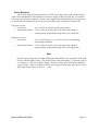
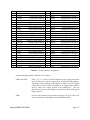
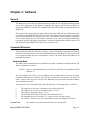
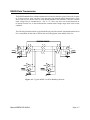
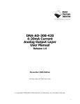
RS485 Data Transmission
The RS485 Standard allows a balanced transmission line to be shared in a party-line mode. As many
as 32 driver/receiver pairs can share a two-wire party line network. Many characteristics of the
drivers and receivers are the same as in the RS422 Standard. One difference is that the common
mode voltage limit is extended and is +12V to -7V. Since any driver can be disconnected (or
tri-stated) from the line, it must withstand this common mode voltage range while in the tristate
condition.
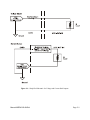
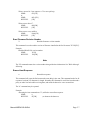
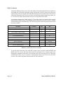
The following illustration shows a typical multidrop or party line network. Note that the transmission
line is terminated on both ends of the line but not at drop points in the middle of the line.
Figure A-1: Typical RS485 Two-Wire Multidrop Network
Manual MRDAG12-8H.Bc1
Page A-3
RDAG12-8 Manual
Page A-4
Manual MRDAG12-8H.Bc1
Appendix B: Thermal Considerations
The low power version of the RDAG12-8 ships installed in a NEMA- 4 box, 8.75" long by 5.75"
wide by 2.25" high. The box has two round openings with a rubber glands for routing and sealing
the I/O cables. When all 8 output channels are loaded with a 10mA load @5Vdc the power
dissipation of the RDAG12-8 is 5.8W. The thermal resistance of the box with an installed
RDAG12-8 card is 4,44EC/W. At Tambient =25EC the temperature inside the box is 47.75EC. The
allowed temperature rise inside the box is 70- 47.75=22.25EC. Thus the maximum ambient
operating temperature is 25+22.25=47.5EC.
The RDAG12-8 high power version can be packaged in several ways:
a) In the T-box (8.5"x5.25"x2") with a 4.5"x.5" slot for cable routing and air circulation.
b) In an open enclosure exposed to free air.
c) In free air with air circulation provided by the customer..
When the high power option is elected, special attention must be paid to heat generation and heat sinking.
The output amplifiers are capable of delivering 3A at output voltage ranges 0-10V, +/-5V, 0-5V.
However the capability to dissipate the heat generated in the amplifiers limits the permissible load
current. This capability is determined in a significant degree by the type of enclosure the RDAG12-8 is
packaged in.
When installed in the T-box the total power dissipation can be estimated using the following
calculations:
The power dissipated in the output amplifier for each channel is:
Pda= (Vs-Vout) x ILoad.
Where :
Pda
Vs
Iload
Vout
Power dissipated in the output power amplifier
Power supply voltage
Load current
Output voltage
Thus if the power supply voltage Vs= 12v, the output voltage range is 0-5V and the load is 40Ohms, the
power dissipated in the output amplifier by the load current is 7V x .125A =.875W. The power
dissipated by the quiescent current Io =.016A. Po=24Vx.016A=.4w. Thus the total power dissipated in
the amplifier is 1.275W. In the idle mode of operation (the outputs not loaded) at 25 EC ambient air
temperature the temperature inside the box (in the proximity of the power amplifiers) is ~45EC. The
power dissipation in the idle mode is 6.7W.
The thermal resistance of the box Rthencl (measured in the proximity of the power amplifiers) is estimated
to be~2EC/W. Thus the allowed output power for a maximum temperature inside the enclosure 70EC is
25EC/2EC/w =12.5W at 25EC ambient air temperature. Thus the allowed total power dissipation with
outputs driving resistive loads is ~19.2W at 25EC ambient temperature.
Derating for the ambient temperature rise is 1/Rthencl = .5W for each degreeC of ambient temperature rise.
Operation In Free Air
Manual MRDAG12-8H.Bc1
Page B-1
RDAG12-8 Manual
The heatsink temperature of the amplifier supplying .250A at 5V DC can reach100EC. max (measured at
ambient room temperature of 25EC). The power dissipated by the amplifier is (12-5)x.250 = 1.750W.
The maximum allowed junction temperature is 125EC. Assuming the junction-to-case and case-to-heat
sink surface thermal resistance for the TO-220 package is 3EC/W and 1EC/W respectively. The junction0-heat sink resistance RJHS=4EC/W. The temperature rise between the heat sink surface and the junction
is 4EC/W x1.75W=7EC. Thus the allowed maximum temperature of the heat sink is 125-107=18EC.
Therefore if any of the channels of the RDAG12-8 has a 250mA load the ambient temperature rise is
limited to 18EC. The allowable maximum ambient temperature will be 25 +18=43EC.
If forced air cooling is provided then the following calculation will determine the allowable load for the
RDAG12-8 allowable power dissipation for the power amplifier:
Pmax = (125EC-Tamb.max)/(RHS +RJHS) where
Heatsink thermal resistance RHS
Junction- to-heatsink surface thermal resistance RJHS
Operating temperature range
Maximum ambient temperature Tamb.max
At air velocity of <100 ft/min
At air velocity of 100 ft/min
Page B-2
Pmax = 3W
Pmax = 5W
= 21EC/W
= 4 EC/W
= 0 - 50EC
= 50EC
(As determined by the heat sink
characteristics )
Manual MRDAG12-8H.Bc1
Customer Comments
If you experience any problems with this manual or just want to give us some feedback, please email
us at: [email protected].. Please detail any errors you find and include your mailing
address so that we can send you any manual updates.
10623 Roselle Street, San Diego CA 92121
Tel. (858)550-9559 FAX (858)550-7322
www.accesioproducts.com