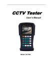
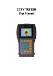
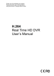
1
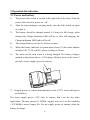
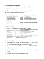
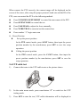
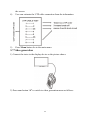
CT-509 CCTV CAMERAS & PTZ TESTER Content 1 Safety information ........................................................................................ 1 1.1 Precaution before using the tester ..................................................... 1 1.2 Precautions when using the tester ..................................................... 1 1.3 Precautions for battery charging and using ....................................... 1 2 Introduction .................................................................................................. 1 2.1 Features and functions ...................................................................... 1 2.2 Standard items .................................................................................. 2 2.3 Function of each part ........................................................................ 3 2.4 Specification ..................................................................................... 4 3 Operation Introduction.................................................................................. 6 3.1 Power and battery ............................................................................. 6 3.2 Main menu introduction ................................................................... 7 3.3 System Setup .................................................................................... 7 3.4 Video test.......................................................................................... 8 3.5 PTZ Test ........................................................................................... 9 3.6 UTP cable test................................................................................. 10 3.7 Video generation .............................................................................11 3.8 RS485 data test ............................................................................... 12 1 Safety information 1.1 Precaution before using the tester 1) Please read the user manual before using the product. 2) Please check the input and output range of voltage or current at every input and output ports before connecting, so that the Tester can not be overloaded / damaged. 3) Operation environment: Working temperature:-30℃~+70℃ Humidity 30%~90% Voltage :DC9V/2000MA 1.2 Precautions when using the tester 1) Do not use the tester in damp humidity or leaking gas environments. 2) Do not touch the tester with wet hands. 3) Do not shock or shake the tester while in use to avoid damage. 4) Avoid using the tester in the places of strong magnetism or electric wave. 5) Do not expose the ports or joints to dirt or liquid. 6) Do not disassemble the tester. 1.3 Precautions for battery charging and using 1) Use only original chargeable battery with the tester, when charge the batteries, please use the original power adapter. 2) Make sure not to disorient the polarization of batteries. 3) Do not short-circuit or disassemble batteries. 2 Introduction 2.1 Features and functions 1) Video test The video signal and the quality of picture can be tested 1 2) PTZ control The unit has the basic operation test of PTZ products, function includes pan/tilt, zoom in/out. Preset setting and operation, auto scanning, speed adjustment etc; support multi-protocol and baud rate, communication via RS422 simplex and RS485 port. RS485 protocol include: Pelco D/P, Samsung, ADT, YAAN, HY, LG, Minking, Vido, and Videotrec etc., special protocols could be customized. Baud rate include: 1200, 2400, 4800, 9600, 19200. 3) UTP cable test The wiring condition (disconnected, short circuit and sequence of UTP cable) can be tested and show in the screen clearly. 4) Video signal generating It can output Black and White screen to allow technician to inspect video monitor or DVR. The generation signal supports PAL or NTSC (do not support both meanwhile) system. 5) RS485 data test It can test the RS485 data sent from control device, display the hexadecimal data content for engineer to analyze. 6) High performance battery Built-in 2000mAh high capacity Li-polymer rechargeable battery and display the battery level on screen. 2.2 Standard items Items Quantity CCTV tester 1 UTP cable tester 1 2 7.4V Battery 1 RS485 connector 1 BNC connect cable 1 Sling 1 Power adapter 1 User manual 1 Test lead set □yes 1 set □No 12V power cable □yes 1 set □No 2.3 Function of each part 3 2.4 Specification Model CCTV Tester Video Signal Test Signal Mode NTSC/PAL automatically suitable Display 2.5 inch LTPS LCD screen , 960 x 240 resolution Video Input 1 Channel BNC Video Output 1 Channel BNC PTZ Test Communication RS485 , RS422 Simplex Protocol Pelco D/P; Samsung, ADT, YAAN, HY, LG, Minking, VIDO, Videotrec or customized. 4 Baud Rate 1200, 2400, 4800, 9600, 19200. Other Functions Supply power to camera Supply power interface on the left of CCTV tester, DC12V/700m (only the CCTV tester with supply power function) UTP Cable Test Test UTP cable connection state and display on the screen. Signal Output 1 channel video signal for testing monitor. Generation RS485 Data Test the RS485 data sent from control device. Test OSD Menu Chinese/English OSD menu Keyboard New design with number buttons, easy to operation. Adapter Power Supply DC9V/2000MA Battery 1 pc Li-polymer rechargeable battery 7.4V, capacity 2000mAh Rechargeable 5 hours recharging time, work for 8 hours or more. Low Sleeping mode, display battery power status. Consumption Other Parameters Work -30°C~+70°C Temperature Work Humidity 30%~90% 5 3 Operation Introduction 3.1 Power and battery 1) The power slide switch is located at the right side of the tester. Turn the power slide switch to power on / off. 2) After the tester turning to sleeping mode, turn the slide switch on again to restart it. 3) The battery should be charged around 4~5 hours for full charge, when charged the Charge indication LED will be on, after full charging, the Charge Indication LED light will be off. 4) The charged battery can use for 8 hours or more. 5) When the battery indicator in system menu shows 25 (the states number includes 100, 75, 50, and 25), please recharge it for use. 6) The tester can be used when it is being charged. The battery changes method as the picture shows: (5 Pin plug of battery insert to the tester 5 pin jack, ensure supply power to camera ) 7) Ssupply power to camera function(only for the CCTV tester with power out interface) The tester supply power +12V only to camera, don’t use for any other application. The max current is 700MA, suggest user use it in the condition +12V/400MA ensure longer life. Do not supply power to camera when the battery in charge. 6 3.2 Main menu introduction Turn on the device; enter the main menu, as the following shows: ● 1-5 are five independent sub-menu. ● Press the corresponding number button to get into the sub-menu. ● Version number and S/N can’t be edited. Pic3-1 3.3 System Setup 1) Press “1” to switch to the system sub-menu, as follows: Pic3-2 2) Press “Set” button to start the set up. 3) Press number “2” and “8” (PTZ direction button “UP” and “DOWN”) to select the option, (Battery power status can be edited). 4) Press num-button “4/6” (PTZ direction button “LEFT/ RIGHT”) to adjust the parameter. 5) Press the “Clean” button to save, the characters in the menu will stop glitter. 6) Press the “Menu” button back to the main menu. 7 Notice: Battery capacity display can’t be adjusted. The device has 16 levels for the PTZ, 001 means minimum speed, 16 means the maximum speed. Standby time can be set from 000~030 minutes. 000 means cancel the standby time. 3.4 Video test 1) Connect the output terminal of video system to the video input BNC of tester, turn on the tester, the video can be displayed on the screen. 2) Connect the video output BNC of tester to the video input of other display device, it can display the video signal generated by the tester. 8 3.5 PTZ Test 1) Connection Connect the tester with the PTZ camera as the picture shows. In the main menu, press num-button “2” to switch to the PTZ testing function sub-menu, as the following: Pic3-3 2) Operation Press the ADR button; input or modify the PTZ address by using num-button. Press the SET button to save the setup. Press the MENU button to hide the menu information and show a clean screen for camera image. Press MENU button for 1 second to back to the main menu. Video System: PAL/NTSC/NULL. When no camera input, display NULL. 3) PTZ Control 9 When connect the PTZ correctly, the camera image will be displayed on the screen of the tester, after setup the proper protocol, baud rate and the ID of the PTZ, user can control the PTZ as the following method: Press UP/DOWN/LEFT/RIGHT to control the movement of the PTZ. Press OPEN/CLOSE to control the iris. Press FAR/NEAR to adjust the focus manually. Press WIDE/TELE to zoom in/out the camera lens. Press number “5” begin auto scan. 4) Preset Position Set up the preset position In the PTZ control mode, press S-PST button, then input the preset position number by the num-buttons, press SET to save the setup operation. Calling the preset position In the PTZ control mode, press the C-PST button, then input the preset position number by the num-buttons, press SET to save the setup operation 3.6 UTP cable test 1) Connect the tester to the UTP cable tester as the picture shows: 2) In the main menu mode, press num-button “3” to switch to the UTP testing mode. 3) Press SET to start the test, UTP cable information will be displayed in 10 the screen. 4) User can estimate the UTP cable connection from the information. 5) Press Menu button for to the main menu. 3.7 Video generation 1) Connect the tester to the display device as the picture shows: 2) Press num-button “4” to switch to video generation menu as follows: 11 Notice: default system is NTSC. 3) Press Menu for 1 second to back to the main menu. Press the Return TO finish the video generation operation, or the Tester couldn’t be switched to other function mode. 3.8 RS485 data test 1) Connect the tester to the control device as the picture shows: 2) In the main menu, press num-button “5” to switch to the RS485 protocol analyzing mode, as follows: 485 DATA CONSTRUE 3) Press SET to start the setup of baud rate. 4) Press UP/DOWN to select the tester’s baud rate, make it same with the controlling device’s. 5) Transfer the controlling device RS485 data to the tester, the 12 hexadecimal signal data will be displayed on the screen as follows. Engineer can analyze the data to know if the controlling devices work with the correct protocol. 485 CONSTRUE FF 01 00 02 40 00 43 FF 01 00 00 00 00 01 FF 01 00 04 40 00 45 FF 01 00 00 00 00 01 13