1
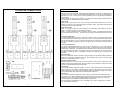
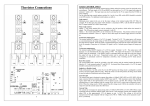
THYRISTOR CONNECTIONS
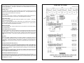
LOGIC CONTROL INPUT
The logic control inputs are optically isolated and are ideally utilised for remote control in electrically noisy
environments. The logic inputs A, B, UP and DOWN are activated by a 5 to 24 V dc signal with respect to
terminal C which is 0 V. The logic input can also be activated by the 5V dc output from the FC36MV via
relay switching.
For the following logic control options, position No.1 on the 6 way DIL switch (SW3) should be switched to
the OFF position. For additional control options see table A.
Logic control
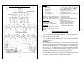
Maximum power output levels are set by the input voltage at the terminal marked SIG I/P. With, for
example, 4V on this input, the output will be limited to a maximum of 80%. Link the SIG I/P terminal to the
5V output terminal for 0-100% control range.
Phase Angle control
Option 1 – the switch marked SW1 can be switched to the ON position, which utilises the internal 5V
supply. This ON position simply connects terminals A with 5V.
Option 2 – the switch marked SW1 can be switched to the OFF position. The position isolates the inputs
and disconnects terminals A from 5V. Inputs A and C then require an external supply between 5 and 24V
dc.
To Increase output power
The terminal marked UP requires a 5 to 24 V dc supply. Terminal C is 0V. The output power will increase
at a rate determined by the ramp setting on VR3 (0-30 seconds). The output will reach its maximum when
the ramp time has elapsed. If the UP signal is terminated during the ramp time the output will remain at
that level, for example, if ramp time is 10 seconds. UP signal is on for 5 seconds, power output will ramp
up to 50%.
To decrease output power
The terminal marked DOWN requires a 5 to 24V dc supply. Terminal C is 0V. The output power will
decrease at a rate determined by the ramp setting of VR3. The output will decrease to zero should the
DOWN signal be maintained. If the DOWN signal is interrupted before the ramp down time has elapsed,
the output will stay at that level. Proportional control can be achieved with an on/off signal. This
arrangement is particularly useful for temperature controllers, relay switching and PC based process
controllers.
Burst Fire control
The switch marked SW1 should be switched to the OFF position and the terminal marked B should be
linked to 5V. Link terminals marked 5V and SIG I/P. For remote Burst Firing control, a 5 to 24V dc signal
should be connected between B and C. C is 0V.
Inductive or Resistive loads
With switch position 3 on DIL switch No.3 in the OFF position, the firing circuit is configured to control
resistive and some slightly inductive loads. When the switch is in the ON position, the firing circuit should
be used on inductive (transformer and coil) type loads.
Current Limit
The current limit input is designed to operate from a 0-5V dc input connected between terminals marked
LIMIT input and 0V. The current limit feedback signal is fed into the microprocessor IC3 and compared
with the voltage set by VR2 (I SET). When the feedback voltage is greater than the voltage on pin 5 (IC3),
the controller will start to ramp down until the current reaches the I SET level.
Current Trip
The current trip is designed to operate from a 0-5V dc input connected between terminals marked LIMIT
input and 0V.). The current limit feedback signal is fed into the microprocessor IC3 and compared with the
voltage set by VR3 (I TRIP). When the feedback voltage is greater than the voltage on pin 7 (IC3), the
controller will shut down immediately and will stay latched in this state until
the microprocessor is powered down or reset. The voltage on pin 7 (IC3) is normally set to 4.2V to allow
for a 120% maximum current level.
8
5