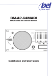
1
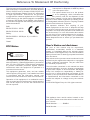
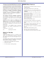
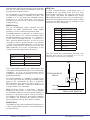
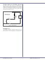
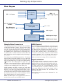
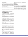
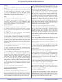
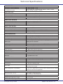
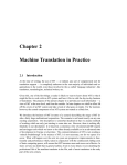
D I GI TAL GROUP SAM64 SDI to AES/MADI interface PSU SDI AES MADI SAM64 SYNC LED INDICATION GREEN: OK RED FLASH: WARNING 1 2 Installation and User Guide WK VID AES SDI-1 Reference To Statement Of Conformity This document confirms that products bearing the CE label meet all the requirements in the EMC directive 2004/108/EC and LV directive 2006/95/EC laid down by the Member States Council for adjustment of legal requirements. Furthermore the products comply with the rules and regulations from 30 August 1995 referring to the electromagnetic compatibility of devices. Bel Digital Group SAM64 units bearing the CE label comply with the following harmonised or national standards: EMC: BS EN 55103-1 :2009 BS EN 55103-2 :2009 Safety: BS EN 60950-1: 2006 (ed. 2) + A1:2010 Insulation: Instructions for Disposal of WEEE by Users in the European Union The symbol shown here is on the product or on its packaging, which indicates that this product must not be disposed of with other waste. Instead, it is the user’s responsibility to dispose of their waste equipment by handing it over to a designated collection point for recycling of waste electrical and electronic equipment. The separate collection and recycling of your waste equipment at the time of disposal will help to conserve natural resources and ensure that it is recycled in a manner that protects human health and the environment. For more information about where you can drop off your waste equipment for recycling, please contact your local city office, your household waste disposal service or where you purchased the product. Class1 FCC Notice Tested To Comply With FCC Standards FOR PROFESSIONAL USE This equipment has been tested and found to comply with the limits for a Class B digital device, pursuant to part 15 of the FCC Rules. These limits are designed to provide reasonable protection against harmful interference when the equipment is operated in a commercial environment. This equipment generates, uses, and can radiate radio frequency energy and, if not installed and used in accordance with the instruction manual, may cause harmful interference to radio communications. Operation of this equipment in a residential area is likely to cause harmful interference in which case the user will be required to correct the interference at his own expense. User’s Notice and disclaimer: No part of this manual may be reproduced, transmitted, transcribed, stored in a database system or translated without the express written permission of Bel Digital Group Ltd. Documentation kept by the end user for back-up purposes is excluded from the above. All products and corporate names mentioned in this manual may be registered trademarks or copyrights of their respective companies. They are used here for indicative purposes only. The information contained in this manual has been carefully checked for accuracy; however no guarantee is given with respect to its correctness. Bel Digital Group Ltd. accepts no responsibility or liability for any errors or inaccuracies that may appear in this manual or the products and software described in it. Specifications and information contained in this manual are subject to change at any time without notice. © 2014 Bel Digital Group Ltd. All rights reserved. This appliance has a serial number located on the rear panel. Please record the serial number here for your records. Model Number…………SAM64 Serial Number………………………………………... 2 SAM64 User Manual v1.6 Bel Digital Group Limited Contents Reference To Statement Of Conformity...... 2 Important Safety Instructions...................... 4 Important Safety Precautions................................... 5 Introduction.................................................... 6 What’s In The Box...................................................... 6 SAM64 Main Features................................................ 6 Front Panel Description............................................ 7 Rear Panel Description.............................................. 8 Installation...................................................... 9 Hardware Considerations........................................ 9 Power Supply Considerations.................................. 9 Fuses And Ratings......................................................................9 Unit Connections....................................................... 9 SDI Inputs....................................................................................9 AES3 Outputs............................................................................9 MADI Outputs........................................................................ 10 RS-422 Port............................................................................. 10 GPIO Port................................................................................ 10 ETHERNET Port.................................................................... 11 Setting Up & Operation.............................. 12 Block Diagram...........................................................12 Sample Rate Converters.........................................12 GPIO Control............................................................12 Synchronisation.........................................................12 Sync To Wordclock............................................................. 13 Sync To Video Black-And-Burst....................................... 13 Sync To AES3........................................................................ 13 Sync To The SDI Inputs...................................................... 13 Clock Outputs.................................................................... 13 Frequently Asked Questions....................... 14 Technical Specifications............................... 15 Bel Digital Group Limited SAM64 User Manual v1.6 3 Important Safety Instructions 1. Read these instructions Power Safety 2. Keep these instructions 18.This apparatus is fitted with a universal power supply, approved and certified for operation in this apparatus. There are no user-replaceable fuses. 3. Heed all warnings 4. Follow all instructions 5. Do not use this apparatus near water 6. Do not expose this apparatus to rain or moisture. 7. Clean only with a dry cloth 8. Do not block any ventilation openings. Install with accordance with the manufacturer’s instructions. 9. No naked flames, such as lighted candles, should be placed on the apparatus. 10.Do not install near any heat sources such as radiators, heat registers, stoves or other apparatus (including amplifiers) that produce heat. 11.There are no user-adjustments, or userservicable items, inside this apparatus. Do not remove the covers of this apparatus; doing so will invalidate your warranty. 19.An external over-current protection device is required to protect the wiring to this apparatus. This protection device must be installed according to current wiring regulations. In certain countries this function is supplied by use of a fused plug. 20.If an extension power cable or adaptor is used, ensure that the total power rating of the power cable and/or adaptor is not exceeded. 21.An external disconnect device is required for this apparatus; a detachable power cord is a suitable disconnect device. 22.The apparatus should be located close enough to an AC outlet so that you can easily grasp the power cord plug at any time. 23.This apparatus is a Class I construction and shall be connected to an AC outlet with a protective grounding connection. 12.Adjustments or alterations to this apparatus may affect the performance such that safety and/or international compliance standards may no longer be met. 24.Protect the power cord from being walked on or pinched, particularly at plugs, convenience receptacles, and the point where they exit from the apparatus. 13.Refer all servicing to qualified service personnel. Servicing is required when the apparatus has been damaged in any way, such as power-supply cord or plug is damaged, liquid has been spilled or objects have fallen into the apparatus, the apparatus has been exposed to rain or moisture, does not operate normally or has been dropped. 25.Unplug this apparatus during lightning storms or when unused for long periods of time. Caution 14.Hazardous voltages may be present inside this apparatus. 15.Do not operate this apparatus with the covers removed. 16.To reduce the risk of electric shock, do not perform any servicing other than that contained in these Installation Instructions unless you are qualified to do so. Refer all servicing to qualified service personnel and ensure that all power cords are disconnected when servicing this apparatus. 17.Only use attachments/accessories specified by the manufacturer. 4 SAM64 User Manual v1.6 26.All power cords must be disconnected to isolate this apparatus completely. 27.Caution: To reduce the risk of electric shock, plug each power supply cord into separate branch circuits employing separate service grounds 28.This equipment is not supplied with a detachable power cord. The device should be connected to a power supply only of the type described in the Installation Guide or as marked on the device. The power cord must be earthed and precautions should be made so that the grounding is not defeated. A mains cord, fitted with an IEC 60320 C13 type socket, appropriate sized conductors and plug to suit local electrical requirements. 29.The power supply cord (i.e. conductor, coupler (IEC60320 C13) and plug combination) must be suitably rated for apparatus and the country of use (meeting local electrical requirements). A power supply cord with a rating of not less than 125% of current rating is suitable. The minimum rating for the power supply cord at 110 / 230V ac to be 1A. Bel Digital Group Limited Installation 30.When installing this apparatus, either fix it into a standard 19” rack or place the apparatus on a secure level surface. When this apparatus is rack mounted, fit all rack screws. 31.Ensure that no strain is placed on the cables connecting to this apparatus. Ensure also that such cables are not placed where they can be stepped on, pulled or tripped over. 32.Do not operate this apparatus whilst it is covered or boxed in any way. Important Safety Precautions CAUTION: TO REDUCE THE RISK OF ELECTRIC SHOCK, DO NOT REMOVE COVER (OR BACK). NO USER-SERVICEABLE PARTS INSIDE. REFER SERVICING TO QUALIFIED SERVICE PERSONNEL CAUTION: RISK OF ELECTRIC SHOCK. THIS EQUIPMENT HAS MORE THAN ONE POWER CORD. TO REDUCE THE RISKS OF ELECTRIC SHOCK DISCONNECT BOTH POWER SUPPLY CORDS BEFORE SERVICING The lightning flash with arrowhead symbol, within equilateral triangle, is intended to alert the user to the presence of uninsulated “dangerous voltage” within the product’s enclosure that may be of sufficient magnitude to constitute a risk of electric shock to persons. The exclamation point within an equilateral triangle is intended to alert the user to the presence of important operating instructions and maintenance (servicing) instructions in the literature accompanying the appliance. Important Safety Information This apparatus has no mains switch or other useroperated control for disconnecting the AC mains power. The mains plugs or the appliance couplers (IEC sockets) are used as the disconnect devices. Either device must remain readily operable and accessible when the apparatus is installed for use. This unit includes thermally resettable fuses that are integral to the power supply circuitry, but the unit must always be powered from a supply fitted with an HRC type (High In-Rush Current) fuse with a rating of 1 A. Bel Digital Group Limited SAM64 User Manual v1.6 5 Introduction Thank you for buying this Bel Digital Group product. The SAM64 SDI to AES+MADI interface is designed to resolve and simplify a common audio infrastructure problem encountered in many broadcast facilities de-embedding the audio data from up to four SDI (Serial Digital Interface) video signals and making it available to the user in AES3 and MADI formats. The SAM64 is a very high quality product, engineered for maximum reliability in professional broadcast environments. It is intended to be “installed and forgotten”, and left in permanent operation. It requires virtually no configuration on installation, or adjustment in normal use. SAM64 Main Features This manual covers the SAM64’s connections and indications, including its various options for synchronisation and external control. Please keep the manual in a safe place once you have installed the SAM64. • MADI bitstream available at both copper (BNC) and optical (ST) outputs Important – Please register your SAM64 with Bel Digital Group Ltd. on-line at www.beldigital.com. Registering your unit will help us in providing you with after-sales service should the need arise, and may also be of assistance in the event of the unit being stolen. Environment – The SAM64’s range of operating temperature and relative humidity (RH) are as follows: Temperature: 5ºC to 40ºC RH: Operating 20 to 80% • De-embeds all 16 channels of audio from each of 4 SDI bitstreams • Auto-sensing of SDI format on each input • Compatible with all current SDI specifications, including SD, HD and 2.9 Gbps 3G (up to 1080p60) • Audio outputs available in 32 x AES3 and 64ch. MADI formats at 48 kHz • MADI output conforms to AES10id-2008; AES3 output to AES3-1992 • Active loop-through SDI outputs • Loop-through outputs transparent to Dolby D/E • Switchable sample rate conversion (SRC) on all inputs • Audio sync to external wordclock, SDI clocks, external AES3 or video black-and-burst • Sync reference outputs in wordclock and AES3 formats • External SRC enable/disable via GPI • GPO tally outputs indicating SRC status • Two independent PSUs with separate IEC inputs What’s In The Box Unpacking Unpack the SAM64 with care. It is always a good idea to store all packaging (if practical), in case you ever need to return the unit to Bel Digital Group for any reason. The shipping carton should contain the items listed below. Please contact your distributor immediately if any of them are missing or damaged. • SAM64 SDI-to-AES/MADI audio interface • Instruction manual • 2 x IEC connector retaining clamp 6 SAM64 User Manual v1.6 Bel Digital Group Limited Front Panel Description PSU SDI AES MADI SAM64 SYNC SRC SDI LOCK LED INDICATION LED INDICATION GREEN: OK RED FLASH: WARNING 1 2 WK VID AES SDI-1 SDI-2 SDI-3 ON SDI-4 1 2 1 3 4 3 4 RED: GREEN: AMBER: SDI FORMAT YELLOW SD-SDI GREEN HD-SDI RED 3G-SDI FLASHING NON-COMPLIANT SDI DETECTED* OFF NO SDI SIGNAL DETECTED * SAM64 monitors all incoming embedded audio streams and if found to be non-compliant in format will flash the appropriate LED. Note that Bel Digital Group cannot guarantee correct operation when non-compliant SDI streams are present. D I GI TAL GROUP SRC control – four 2-position toggle switches controlling the four 16-channel output SRCs. The switch also enables external GPI control of each SRC. SWITCH POSITION COLOUR 3G HD SD NO VALID SIGNAL IF SDI LOCK LED OFF GPI CONTROL SDI Lock LEDs – four tri-colour LEDs, for SDI inputs 1 to 4. Each illuminates continuously when a valid SDI video signal is detected at its input, and the colour indicates the interface standard in use, as below: 2 FUNCTION UP SRC ON DOWN SRC OFF, BUT UNDER EXTERNAL GPI CONTROL PSU status – two bi-colour LEDs confirming the current status of each PSU. The LEDs are green in normal operation and flash red if a PSU fault condition is detected. Sync source selection – a 3-position toggle switch for selecting the audio sync source. The switch’s ‘down’ position is latching, while its ‘up’ position is momentary. Repeated ‘upward’ presses on the switch scroll through the possible external sync sources. The adjacent amber LEDs indicate the currently-selected source. When the LED for the desired source is on, the switch may be placed in the latching ‘down’ position to prevent inadvertent further changes of sync source. SWITCH POSITION FUNCTION CENTRE NO ACTION UP (MOMENTARY) INCREMENTS SYNC SOURCE SELECTION DOWN (LATCHES) LOCKS SYNC TO CHOSEN SOURCE Bel Digital Group Limited SAM64 User Manual v1.6 7 Rear Panel Description 8 SDI video inputs 1 to 4 (4 x BNCs) – internally illuminated green SDI video active loopthrough outputs 1 to 4 (4 x BNCs) - internally illuminated red AES3 outputs (37-way female Dsub) Co-axial MADI output (BNC) Optical MADI output (ST) Ext. Ref input (BNC) Wordclock out (BNC) AES3 sync out (BNC) GPI/O port (9-pin female Dsub) RS-422 port (9-pin female Dsub) Ethernet port (RJ45) AC inputs – 2 x IEC sockets SAM64 User Manual v1.6 Bel Digital Group Limited Installation Hardware Considerations The SAM64 is built in a 1U 19” enclosure. It is intended to be permanently installed in a standard 19” equipment rack. There are ventilation grilles in the top, bottom and both sides of the enclosure, and care must be taken to ensure that these are not blocked by cables or other equipment when the unit is installed. Do not install any other items of equipment immediately above or below to the SAM64; the use of 1U blanking panels is recommended. Power Supply Considerations AES3 Outputs The 64 audio channels de-embedded from the four SDI inputs are available as 32 AES3 digital audio outputs on the rear panel 37-way female Dsub connector. The outputs are unbalanced (AES3id), but are compliant with AES3-1992 in all other respects. The table below gives the pinout: PIN OUTPUT SDI SOURCE AUDIO CHANNELS 1 AES 1 2 AES 2 3 AES 5 4 AES 6 Chs 11 & 12 5 AES 9 Chs 1 & 2 6 AES10 7 AES 13 8 AES 14 Chs 11 & 12 If redundant operation is not required, only one AC supply cable need be connected; either AC inlet may be used. 9 AES 17 Chs 1 & 2 10 AES 18 11 AES 21 Fuses And Ratings 12 AES 22 Chs 11 & 12 Each of the SAM64’s PSUs has an internal resettable fuse for PSU protection. These fuses are not accessible to the user. The unit should be powered from a mains supply (supplies) fitted with an external HRC-type fuse (High Inrush Current) rated at 1 A. 13 AES 25 Chs 1 & 2 14 AES 26 15 AES 29 16 AES 30 17 n/c 18 n/c SDI Inputs 19 GND The SAM64 can simultaneously de-embed the 16 audio channels in each of four separate SDI video signals. Four BNC sockets are provided at the rear panel for connecting the SDI inputs. The characteristic impedance is 75 Ω . The SAM64 is compatible with all SDI formats up to 3G (2.9 Gbps) and auto-detects between them. See the Technical Specifications on page 16 for full list of compatible formats. 20 AES 3 21 AES 4 22 AES 7 23 AES 8 Chs 15 & 16 24 AES 11 Chs 5 & 6 25 AES 12 26 AES 15 Each SDI input has an active “loopthrough” output, to simplify the connection of further equipment. The outputs are fully buffered from the inputs and are reclocked. The SDI bitstream is otherwise unaltered. 27 AES 16 Chs 15 & 16 28 AES 19 Chs 5 & 6 29 AES 20 Note: recomendation is that cable lengths be 3 m in length or less. 30 AES 23 31 AES 24 Chs 15 & 16 32 AES 27 Chs 5 & 6 33 AES 28 34 AES 31 35 AES 32 36 n/c 37 GND The SAM64 is fitted with two separate, auto-ranging switch-mode power supplies (PSUs). The operating voltage range is 100 to 240 V AC, 50/60 Hz. The internal power rails are diode-paralleled to the two supplies, and the unit will operate normally if only one PSU is powered or functional. For maximum protection when using both PSUs, the two AC inlet cables should be connected to mains circuits which are as independent of each other as possible. Unit Connections Bel Digital Group Limited Chs 1 & 2 SDI 1 SDI 2 SDI 3 SDI 4 Chs 3 & 4 Chs 9 & 10 Chs 3 & 4 Chs 9 & 10 Chs 3 & 4 Chs 9 & 10 Chs 3 & 4 Chs 9 & 10 Chs 11 & 12 Chs 5 & 6 SDI 1 SDI 2 SDI 3 SDI 4 Chs 7 & 8 Chs 13 & 14 Chs 7 & 8 Chs 13 & 14 Chs 7 & 8 Chs 13 & 14 Chs 7 & 8 Chs 13 & 14 Chs 15 & 16 SAM64 User Manual v1.6 9 Note that each AES3 output carries 2 audio channels, thus the 16 audio channels embedded in each SDI input generate 8 AES3 outputs. To aid installation, an optional AES3-id Signal Break Out accessory (ASBO) is available from Bel. This consists of a 1U 19” panel with 32 BNC sockets, prewired to a 37-way Dsub plug. This may be mounted at the front or rear of the rack and greatly simplifies wiring. GPIO Port A GPIO (General-Purpose Input-Output) port is available at the rear panel in the form of a 9-pin female Dsub connector. This has four inputs and four outputs, and allows the SAM64’s four output SRCs (Sample Rate Converters) to be enabled from external control equipment by contact closure. Tallies confirming the SRC status are also available on this connector. Pinout is as follows: MADI Outputs The 64 de-embedded audio channels are also available as MADI (Multichannel Audio Digital Interface), in both co-axial and optical formats. The MADI bitstream contains all 16 channels from all four SDI inputs. The channel numbering within the MADI bitstream is one-to-one, i.e., Channel 1 of SDI 1 becomes MADI Channel 1, Channel 2 of SDI 1 becomes MADI Channel 2, and so on for the remainder of SDI 1’s audio channels. Then Channel 1 of SDI 2 becomes MADI Channel 17, and the cycle repeats. If less than four SDI inputs are in use, the MADI bitstream time slots corresponding to the unused inputs will simply contain all zeroes. SDI INPUT MADI CHANNELS SDI 1 1 to 16 SDI 2 17 to 32 SDI 3 33 to 48 SDI 4 49 to 64 The co-axial MADI output is on a BNC socket, and is compliant with AES10id-2008. The characteristic impedance is 75 Ω, at a nominal data rate of 125Mbps. Transmission distances up to 50 m are generally achievable. The same bitstream is available in optical format on an ST type connector, allowing the MADI output signal to be transmitted by fibre if preferred. Recommended fibre types are 62.5/125 μm or 50/125 μm, multimode. Transmission distances of at least 1000 m are achievable. Note: Firmware Version 4 and earlier - with the exception of video sync, no audio will be available on the MADI outputs if incorrect synchronisation is selected, or the synchronisation source is invalid or not present. From Version 5, audio will be available, but SAM64 will automatically flywheel (internal synchronisation) until the sync issue is rectified. PIN FUNCTION 1 GPI 1 2 GPI 2 3 GPI 3 4 GPI 4 5 GND 6 TALLY 1 7 TALLY 2 8 TALLY 3 9 TALLY 4 The GPI inputs are opto-isolated internally, and activate when the pin is connected to 0 V. (i.e. connect pins 1-4 to pin 5 to activate). Vcc OPTO-ISOLATED GPI INPUTS PIN 1* PIN 5 *PINS 2-4 ARE IDENTICAL RS-422 Port The SAM64’s rear panel includes an RS-422 port on a 9-pin female Dsub connector. This functionality is not implemented. 10 SAM64 User Manual v1.6 Bel Digital Group Limited The tally outputs are open-collector type, with transistors rated at 24 V. The tallies will typically be used to drive LEDs; connect the cathode of the LED to the tally output and the anode, via a suitable resistor, to an external DC voltage of not more than +24 V. The 0 V reference of the external DC voltage should be connected to pin 5. OPEN-COLLECTOR TALLY OUTPUTS + LED EXT PSU PIN 6* 0V - PIN 5 *PINS 7-9 ARE IDENTICAL ETHERNET Port The SAM64 includes a standard Ethernet port (an RJ45 socket). This functionality is not implemented. Bel Digital Group Limited SAM64 User Manual v1.6 11 Setting Up & Operation Block Diagram SDI 1 – 4 inputs Auto-sensing SDI De-embedder SDI 1 – 4 Loop-through outputs SDI Lock LEDs Local and remote control of SRCs Sync References Inputs & Outputs Sample rate converters (with bypass) SRC On LEDs AES outputs MADI Optical Output MADI interface MADI Coaxial Output Sample Rate Converters GPIO Control The sampling frequency of the audio data embedded in SDI video signals is 48 kHz. This is invariant, and is enshrined in the defining standards for all SDI formats. As with all operations involving digital audio, it will generally be desirable for the audio outputs of the SAM64 to be synchronised (in frequency and/ or phase) with a master reference clock, which will also synchronise all other digital audio processing in the facility. As the SAM64 could be installed in a central control room or outside broadcast vehicle using automated system software applications, external control of the SRCs can be achieved via the GPIO port. Simple contact closure (grounding the GPI) enables any or all the SRCs, allowing them to be switched in or out from a remote point. Maximum recommended operating distance is 5 m (though this may be increased by the use of external relays or similar). To achieve this, the SAM64 includes four 16-channel Sample Rate Converters (SRCs), one for each SDI input (see Rear Panel Description on page 8). Each SRC may be switched in or out by a front panel switch (see Front Panel Description on page 7) or by external control via the GPIO port. When each SRC is active, a red LED illuminates, and a tally output voltage is also available at the rear GPIO port. Refer to the pinout on page 10 for wiring details. When enabled, the SRCs re-clock the audio data against the sync reference ensuring that the word blocks in the data are phase-locked exactly to the reference clock. The SAM64 allows the user to select a reference clock source to suit the infrastructure of the facility and the nature of the transfer process. See following section on “Synchronisation”. Synchronisation The SAM64 should normally be used as a slave device, synchronised to an external clock reference. SAM64 offers a choice of synchronisation sources. Selection is made from the front panel, and the array of LEDs confirms the currently-selected source. The selected source is used as reference for all four output SRCs, thus ALL audio outputs, both in AES3-id and MADI formats, will be locked to the selected reference. The various clock sources are discussed on the following page. Note: If the SDI inputs are not phase-locked, then no audio will be present on the MADI output. 12 SAM64 User Manual v1.6 Bel Digital Group Limited Sync To Wordclock SRC sync to an external wordclock is indicated by illumination of the ‘WK’ front panel LED. The clock source should be connected to the REF IN connector (a BNC socket) on the rear panel and each SRC front panel switch should be set to ON. Nominal frequency is 48 kHz 50ppm, and clock pulses should be of 5 V amplitude, positive-going. Note: The wordclock input includes integral 75 ohm termination. Use the wordclock output connector to daisy-chain wordclock to other devices. Note: With synchronisation set to wordclock, if no valid sync source is detected the front panel WK LED will flash. Note: Passing Dolby-encoded material through sample rate converters will corrupt the Dolby bitstream. Clock Outputs A reference clock output is available at the rear panel WK OUT connector in the form of a 48 kHz clock signal, of 5 V amplitude, positive-going, or at the AES OUT connector in the form of an AES3 digital audio signal (“digital silence”). These are derived from whichever synchronisation source is selected. If the incoming sync source chosen is one of the four SDI inputs ensure that the wordclock output (WK OUT) is used as the audio system’s Master Sync source. Note: If no valid sync source is detected there will be no MADI output (firmware v4 and earlier only). Sync To Video Black-And-Burst The SAM64 can also synchronise to a standard (SD) 1 V black-and-burst video signal. The video signal should be connected to the REF IN connector on the rear panel. The sync input auto-detects NTSC or PAL standard video. Note: With synchronisation set to video, if no valid sync source is detected the front panel VID LED will flash (from firmware v5 only) . Sync To AES3 An AES3-compliant digital audio source may be used as the clock reference source. The internal 48 kHz wordclock source is phase-locked to the incoming AES3 signal. Any audio data contained in the AES3 word will be ignored. The audio source should be compliant with AES3-id for 75 ohm coaxial transmission and connected to the REF IN connector on the rear panel. Note: With synchronisation set to AES, if no valid sync source is detected the front panel AES LED will flash (from firmware v5 only) . Sync To The SDI Inputs Any of the four SDI inputs may be used to reference the audio outputs. The audio present in Group 1 of the selected SDI source is extracted and used to derive the sync source. If one or more pairs of audio channels in an SDI signal is carrying Dolby-encoded material, the SRC for that input should be set OFF, and that input should be the sync referenced source. Note: Use the derived wordclock output (WK OUT) as the Master Sync reference for all downstream equipment. Note: If using this method, it is important to consider how the remaining three SDI sources synchronise in relation to the sync source. If the inputs are asynchronous then they should have their SRCs set to ON. This ensures that the audio content will synchronise to the referenced SDI input. Bel Digital Group Limited SAM64 User Manual v1.6 13 Frequently Asked Questions Power: Q: Can I run SAM64 with just one PSU (AC inlet) cable? A: Yes, although it is always recommended that two AC inlet cables are connected in order to provide a level of redundancy. The two AC inlet cables should be connected to mains circuits which are as independent of each other as possible. a) The sample rate converters compensate for any minor frequency differences between the incoming SDI 48 kHz and the reference 48 kHz, thus locking the audio to the reference 48 kHz. A: SAM64 automatically determines what the incoming SDI format is and configures itself accordingly. Status of each individual SDI input (SD, HD or 3G) is indicated on the front panel. b) The sample rate converters are used to phase align the audio content within the independent SDI sources prior to them being combined and transmitted as a MADI stream. Unless synchronising to an SDI source that incorporates Dolby ® encoded material it is important to ensure that all four SRC switches are set to ON. If set to OFF it could be possible for audible clicks to be present on the MADI receiving device. Note: If SAM64 detects that phase alignment between incoming SDI streams is significantly out (and that all SCRs are set to OFF), SAM64 will mute the MADI output. Synchronisation: Q: When should an SRC switch be set to OFF? Q: SAM64 is not synchronising to wordclock. A: The only time an SRC switch should be set to OFF is when Dolby ® content is embedded within the SDI stream. If this situation does arise then SAM64 synchronisation must be set to reference that specific SDI input. SAM64 will then become the sync master reference source. Ensure that other equipment then synchronises to the unit’s Wordclock output (WK Out). SDI: Q: How do you select between SDI formats? A: Ensure that the incoming wordclock is derived from a 75 ohm terminated source, as per the AES11 standard. Q: What is the most commonly recommended configuration for synchronisation? A: The most commonly used and recommended synchronisation method for SAM64 is slaving it to wordclock via the Ref In connector. Ensure that wordclock sync has been selected using the front panel selection switch (WK LED should illuminate) and that all four sample rate converter switches are set to ON. Q: Can I daisy-chain other devices to SAM64 to when synchronising to Wordclock? A: This is possible by using the wordclock loopthrough connector (WK Out). WK Out is a buffered copy of the incoming wordclock. Q: Can SAM64 be used as a master sync generator? Note: only one SRC should be set to OFF at any one time. The possibility of sync issues could arise if the separate SDI sources are not phase aligned. Q: Can Sample Rate Conversion be applied to the AES outputs? A: Yes, depending whether the SRCs are set to ON or not. If set to OFF, synchronisation of each AES pair will be as per the specific input SDI source. Audio Outputs: Q: Is there an easier way to access the AES outputs than wiring directly to the 37-way Dsub? A: In the majority of installations SAM64 should not be used as a master sync generator. The only situation that would dictate use as a master clock reference would be when SAM64 is synchronised to an incoming SDI source that contains Dolby® bitstreams. In this situation the appropriate SDI’s Sample Rate Converter (SRC) switch should be set to OFF and all other external audio equipment should be synchronised to the SAM64’s wordclock output (WK Out). A: Yes, Bel also manufacture a 1U AES3-id breakout unit (ASBO) that connects directly to SAM64 and provides the 32 unbalanced AES outputs on BNC connectors (75 ohm). Contact your Bel dealer for further information. Q: Is the wordclock input terminated? Recommended fibre types are 62.5/125 μm or 50/125 μm, multimode. An ST type fibre optic connector is fitted to SAM64. A: Yes, it is internally terminated at 75 ohms. Sample Rate Converters: Q: What are the Sample Rate Converters for? A: In the traditional sense, Sample Rate Converters (SRC) do as they say; convert an incoming or outgoing audio source from one sample rate to another. In the case of SAM64, the SRCs perform two functions: 14 SAM64 User Manual v1.6 Q: Are the audio outputs always available? A: Yes, de-embedded audio is simultaneously available as 32 x AES3-id, and optical+coaxial MADI. Q: What fibre optic MADI cable should I use? Q: I have no MADI output? A: Check that synchronisation is valid. Audio will not be present on the MADI output if synchronisation is invalid (firmware version 4 and earlier only). Firmware version 5 allows SAM64 to flywheel using its internal sync source if an external source is lost. Bel Digital Group Limited Technical Specifications VIDEO INPUTS Connector/input impedance 4 x BNC sockets, 75 Ω Compatible formats SDI, SD/HD/3G, compliant with SMPTE 259M, 296M, 274M, 292M, 424M or 425M VIDEO OUTPUTS Connector/output impedance 4 x BNC sockets, 75 Ω Format Active, re-clocked loop-through of SDI inputs AUDIO INPUTS Format Extracted from SDI video inputs AES3 AUDIO OUTPUTS Connector/output impedance 37-way female Dsub, 32 x 75 Ω unbalanced Format Compliant to AES3-1992 Sampling frequency 48 kHz nominal MADI AUDIO OUTPUT Connector/output impedance (coaxial) BNC socket, 75 Ω Connector (optical) ST Multimode Format 64-channel, compliant with AES10id-2008 Data rate 125 Mbps ±25ppm SYNCHRONISATION Sample Rate Conversion SRC available on all inputs, switchable in banks of 16 Sources (External): SDI1 to 4, AES3, Video black-and-burst, Wordclock Video sync input PAL/NTSC 50/60 Hz (SD) Wordclock input 48 kHz ±50ppm, DC coupled, positive going pulses AES3 input AES3 input at fs=48 kHz Wordclock output 48 kHz nominal AES3 output Digital audio signal compliant with AES3-1992 GPIO PORT GPIO port – connector 9-pin female Dsub Input functions 4 x SRC select (short-to-ground) Output functions 4 x SRC status (open-collector) OTHER CONTROL RS-422 9-pin female Dsub – for possible future use Ethernet For possible future use POWER SUPPLY Type 2 x independent switch-mode regulated, auto-ranging Inputs 2 x 100 to 240 V AC, 50/60 Hz Power consumption 16 W Connectors 2 x IEC with retaining clips Fuse data Internal fixed resettable (non-user-accessible). Use a 1 A HRC externally-fused supply Electro Magnetic Compatibility EN 55103-1 :2009, EN 55103-2 :2009. Environments E1, E2, E3, E4, E5. Initial Inrush current 30A. Braid-screened cables should be used where applicable. PHYSICAL Dimensions (w x d x h) 483 x 200 x 44.5 mm (1U) 19 x 7.87 x 1.75 inches (1U) Weight 4.5 kg / 10 lbs Operating temperature range 5ºC to +40ºC Relative humidity range Operating 20 to 80% Bel Digital Group Limited SAM64 User Manual v1.6 15 Bel Digital Group Limited 3 Horwood Court Bletchley Milton Keynes MK1 1RD United Kingdom Tel: +44 (0)1908 641063 Email: [email protected] URL: www.beldigital.com