1
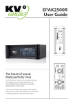
EPAK 2500R
OPERATOR’S MANUAL
EPAK 2500R CONTROLLER/AMPLIFIER UNIT
IMPORTANT SAFETY INSTRUCTIONS
Before using your EPAK 2500R, be sure to carefully read the applicable items of these
operating instructions and the safety suggestions
1. Keep this manual for future reference.
2. Heed all warnings.
3. Follow all instructions.
4. Do not use this unit near water. Do not spill water or other liquids into or on the unit. Do not
operate the EPAK 2500R while wet or standing in liquid.
5. Clean only with dry cloth.
6. Do not block the air intake or exhaust ports. Install the unit in accordance with the
instructions.
7. Do not operate the EPAK 2500R near heat producing devices such as radiators, heat registers,
stoves or other apparatus that produce heat.
8. Always operate the unit with the chassis ground wire connected to the electrical safety earth.
Do not defeat the safety purpose of a grounding-type plug. A grounding type plug has two
pins and a third grounding prong. The third prong is provided for your safety. If the provided
plug does not fit into your outlet, consult an electrician for replacement of the obsolete outlet.
9. Connect only to AC power outlets rated 115-250V, 50-60Hz.
10. Do not use this EPAK 2500R if the power cable is broken or frayed. Protect the power cable
from being walked upon or pinched particularly at the plugs and the point where it exits from
the apparatus.
11. Only use accessories specified by the manufacturer.
12. The unit is intended to be used in a 19” rack. Follow the mounting instructions. When a rack
on wheels is used, use caution when moving the loaded rack to avoid injury from tipping over.
13. Unplug this apparatus during lightning storms or when unused for long periods of time.
14. Do not connect an EPAK 2500R output in parallel or series with any other EPAK 2500R’s
output. Do not connect the EPAK 2500R output to any other voltage source, such as battery,
mains source, or power supply, regardless of whether the EPAK 2500R is turned on or off.
15. Do not run the output of any EPAK 2500R back into another channel's input.
16. Refer all servicing to qualified service personnel. Servicing is required when the apparatus has
been damaged in any way such as:
• Power-supply cord or plug is damaged
• Liquid has been spilled into the unit
• An object has fallen into the unit
• The unit has been exposed to rain or moisture
• The unit does not operate normally
• The unit was dropped or the enclosure is damaged
17. Do not remove top or bottom covers. Removal of the cover will expose hazardous voltages.
There are no serviceable parts inside and removal may void the warranty.
18. An experienced user shall always supervise this professional audio equipment, especially if
inexperienced adults or minors are using the equipment.
CAUTION: TO REDUCE THE RISK OF ELECTRIC SHOCK, DO NOT REMOVE THE COVER.
NO USER-SERVICEABLE PARTS INSIDE. REFER SERVICING TO QUALIFIED PERSONNEL.
WARNING: To prevent fire or electric shock, do not expose this equipment to rain or moisture.
INDEX
1. Introduction
2. Getting Started
2.1 Unpacking
2.2 Rack Mounting
2.3 Cooling
2.4 AC Requirements
3. Features
3.1 Front panel
3.2 Rear panel
4. Using the System
4.1 Normal Set Up
4.2 Using the Mid/Hi Insert
4.3 Feeding the Subwoofers from another source
5. Specifications
6. Block Diagram
7. Warranty Service & Contact Information
1
INTRODUCTION
Thank you for purchasing this KV2 Audio EPAK 2500R controller/amplifier unit. This
manual contains important information on operating this unit correctly and safely.
Please take some time and read this manual to familiarise yourself with the advanced
features of this unit.
The EPAK 2500R is a four-way, active control and amplification system specifically
designed for the KV2 Audio ES Series™ modular loudspeaker systems. It houses all
signal processing and amplification as well as providing control for six different
subwoofer cabinet configurations, powered by the internal subwoofer amplifier, along
with providing control signal to an external VHD3200 subwoofer amplifier to power
further subwoofer cabinets if needed.
The amplifier compliment inside the EPAK 2500R is as follows:
High Frequency - 100-watt, Class AB, push pull, low intermodulation design.
Mid Frequency - 200-watt, Class AB, push pull, low intermodulation design.
Mid Bass - 600-watt, high-efficiency, current-enhancing switch mode technology with
Linear Active Filter.
Subwoofer - 1600-watt, high-efficiency, current-enhancing switch mode technology
with Linear Active Filter.
The EPAK 2500R is “Line Driver Ready” and has its own input impedance selector switch
on the rear panel to accurately match up the input impedance to the output of any
mixer used. In most cases it would be advisable to use a VHD LD4 line driver in addition
at the mixer end to ensure that the line to the amplifier is driven correctly and the signal
integrity maintained.
Although this unit is simple to operate improper use can be dangerous. This is a very
high-powered device that can put out high voltages and sizeable currents. Always use
safe operating techniques with the EPAK 2500R.
FOR YOUR SAFETY, READ THE IMPORTANT PRECAUTIONS SECTION AS WELL AS
THE INPUT, OUTPUT AND POWER CONNECTION SECTIONS OF THIS MANUAL.
2
GETTING STARTED
2.1 UNPACKING
Unpack the EPAK 2500R and check to see if there is any damage to it. If you find any
damage notify your supplier immediately. Only the consignee may institute a claim
with the carrier for damage incurred during shipping. Be sure to save the carton and
all packing materials for the carrier's inspection.
Should you ever need to ship the unit, only use the original factory packaging. If the
shipping carton is unavailable, contact your supplier to obtain a replacement.
The EPAK 2500R carton should contain:
• EPAK 2500R amplifier control unit
• User's manual
• PowerCon detachable power cable
2.2 RACK MOUNTING
EPAK 2500R’s will mount in standard 19" rack systems. Integral rear mounting rack
ears are also provided for additional support, do not rely on fixing and mounting the
EPAK 2500R using just the front panel as support. Use eight screws and washers to
mount the amplifier to the equipment rack rails (four for the front and four for the
rear). We recommend using a shock mounted rack for touring use to prolong the life
of your EPAK 2500R.
)5217 3$1(/
PP
INPUT
Z
PP
7(&+12/2*<
SUB SET UP
3
4
2
5
1
6
ON
POWER/
SERVICE
POS.
1.
2.
3.
4.
5.
6.
INTERNAL
ES1.8+ES1.5
2x ES1.5
2x ES1.8
ES2.5
ES2.5
ES2.5
HI FREQ LEVEL
EXTERNAL
ES1.8+ES1.5
2x ES1.5
2x ES1.8
ES2.5
2x ES1.8
2x VHD1.21
-1
0
+1
+2
-2
+ 3dB
-3dB
ES1.0 SYSTEM
SIGNAL
PRESENT
1 PER SIDE
2 PER SIDE
SUB LEVEL
LIMIT/
THERMAL
EXT SUB LEVEL
0
-3
MASTER LEVEL
0
+3
-3
0
+3
-3
+3
UNPROPER
USE
-6dB
5($5 3$1(/
MAIN
INPUT
INPUT
Z
+ 6dB
-6dB
+ 6dB
-6dB
6,'( 3$1(/
PP
THROUGHT
SIGNAL OUT
250 VAC
10 kΩ
7(&+12/2*<
230 VAC
PP
ES 1.0
115 VAC
50 Ω
MID/HI
IN
+ 6dB
PRE CONTROL
OUT
WARNING
HIGH VOLTAGE: DO NOT REMOVE THIS PANEL
CAUTION
INTERNAL
SUB IN
WARNING: RISK OF ELECTRIC SHOCK DO NOT OPEN
AVIS: RISQUE DE CHOC ELECTRIQUE NE PAS OUVRIR
INTERNAL
SUB OUT
EXTERNAL
SUB IN
EXTERNAL
SUB OUT
230
115 VAC,
VAC, 50/60
50/60 Hz
Hz
MAX 2800WATTS
AC IN
TO ENSURE PROPER OPERATION ALLOW A MINIMUM OF 6 INS. CLEARANCE
FROM THIS SURFACE AND ADEQUATE VENTILATION. TO REDUCE THE RISK OF
ELECTRIC SHOCK. DO NOT REMOVE THIS PANEL OR ANY ATTACHED COMPONENT.
NO OPERATOR SERVICEABLE PARTS INSIDE. REFER SERVICING TO QUALIFIED
PERSONNEL. TO REDUCE THE RISK OF FIRE OR ELECTRIC SHOCK, DO NOT EXPOSE
THIS APPLIANCE TO RAIN MOISTURE
PP
2
GETTING STARTED
2.3 COOLING
The EPAK 2500R has a comprehensive cooling system featuring chassis-sealed PCB board
mounting and shock mounted, speed controlled fans. This means that the cooling system
never drives air across PCB boards, connectors or components ensuring prolonged
electronic component lifespan and minimizing maintenance cycles.
Air is drawn into the front of the amplifier by the two fans on the rear panel, this passes
over the cooling fins of the heat sinks and exhausts through the rear. If the heat sink gets
too hot, its sensing circuit will open the output relay, disconnecting the load.
It is important to have an adequate air supply at the front of the amplifier, and enough
space around the rear of the amplifier to allow the cooling air to escape. If the unit is
rack mounted, do not use doors or covers on the rear of the rack; the exhaust air must
flow without restriction. If you are using racks with closed backs, use fans on the rear
rack panel to ensure an ample air supply
2.4 AC REQUIREMENTS
A PowerCon cable is provided to connect the EPAK 2500R to a suitable AC power supply.
The PowerCon is a connector without breaking capacity, i.e. the PowerCon
should not be connected or disconnected under load or while it is live.
Always isolate your AC supply before disconnecting the PowerCon connector.
Your EPAK 2500R will be supplied pre set to the voltage used in your area. The table
below provides typical current draw figures for the EPAK 2500R.
AC Input
Current draw with
amplifier running at Average
Power (Each Channel)
Current draw with
amplifier running at
Peak Power (Each Channel)
250V
8.25A
12.5A
230V
9A
14A
115V
18A
28A
3
FEATURES
3.1 FRONT PANEL
1
2
3
4
5
6
11
1) AC Mains Switch
The EPAK 2500R has a combination AC Mains
switch/circuit breaker on the front panel. If the
switch shuts off during normal use, push it
back to the ON position once. If it will not stay
on you should take the unit to qualified service
personnel to have it serviced.
2) Unproper Use LED
If the EPAK 2500R is connected improperly then
this LED will light and the unit will shut down.
3) Limit / Thermal LED
This is a dual colour LED, when green it
indicates that the audio limiter has been
activated. When red it indicates that the
thermal limit of the EPAK 2500R has been
exceeded and the unit has shut down because
of this.
4) Power / Service LED
This is a dual colour LED, when green it
indicates that the AC power is on. When red it
indicates that there is a fault condition sensed
within the EPAK 2500R and that the unit
needs servicing.
5) Signal Present
This green LED indicates when audio signal is
present at the EPAK 2500R’s input.
8
7
10
9
6) Sub Set Up
This switch is set according to which
combination of subwoofers is being used with
the system. Refer to ‘Using the System’ for
further information, the various combinations
are listed in the table within this section.
7) Hi Freq Level
This controls the output level of the high
frequency amplifier to enable you to adjust the
high frequency component of the ES system to
the desired level.
8) ES 1.0 System
This switch sets the controller for use when
either a single ES 1.0 is being used or a double
system using 2 ES 1.0’s are being used. In this
mode another EPAK 2500R would be required
to power the second ES 1.0 and both switches
should be set to ‘Double’.
9) Master Level
This is the master level control for the system
and will affect both the ES 1.0 and the
subwoofer outputs.
10) Ext Sub Level
This is the level control for the External Sub
output; it is ‘post’ the Master Level control.
11) Sub Level
This is the level control for the Internal Sub
output; it is ‘post’ the Master Level control.
3
FEATURES
3.2 REAR PANEL
1
2
3
4
5
6
1) Main Input / Through Signal Out
This is the main system input connector with
associated ‘Through Signal Output’ connector
for sending unprocessed signal to other devices,
such as more EPAK 2500R’s to power more
ES 1.0’s in a system.
2) Input Z
This switch selects one of two input impedance
settings for the EPAK 2500R. The switch should
be set to the 50Ω setting when the EPAK 2500R
is driven from a VHD LD4 line driver. Where an
LD4 is not being used and the EPAK 2500R is
being driven from a standard mixing console
output, then the 10kΩ setting should be used.
3) Mid/High In / Pre Control Out
This is an insert point for the Mid/High section
of the EPAK 2500R, the signal sent to the ES 1.0
cabinet. It enables you to ‘insert’ an external
device (a delay line for example) into the signal
that is being sent to the ES 1.0. With the
associated switch in the ‘Engage’ setting the Pre
Control Out connector would send the signal to
the external device, and its output would be
returned into the Mid/High In connector.
4) Internal Sub In
This ‘insert’ point allows you to drive the
internal subwoofer amplifier from an external
source. The signal for the internal subwoofer
amplifier is usually derived from the Main Input
on the EPAK 2500R but with this Sub In and
associated switch the option is available to
derive the signal input for the internal
subwoofer section from a different source. For
further information see ‘Using the System’.
7
8
9
5) External Sub In, External Sub Out
Apart from providing signal processing and
power amplification for driving the ES 1.0
enclosure and ES subwoofers the EPAK 2500R
also provides processed outputs for feeding
VHD 3200 subwoofer amplifiers to drive various
combinations of ES and VHD subwoofers. The
signal for this is usually derived from the Main
Input on the EPAK 2500R but with these Sub In
and Sub Out connectors and associated switch
the option is available to derive the signal input
for the external subwoofer section from a
different source. For further information see
‘Using the System’.
6) PowerCon Power Connector
Accepts a standard PowerCon terminated AC cable
7) Fans
The cooling fans operate continuously while the
EPAK 2500R is on. An internal temperature
sensor increases the speed of the fans during
high temperature conditions. Air enters through
the front grille and exits through the rear. Be
sure to allow adequate air flow to the front of
the rack in which the EPAK 2500R is mounted.
8) ES 1.0 EP6 Connector
Accepts a standard EP6 terminated loudspeaker
cable for connecting up to a single ES 1.0
cabinet. We recommend using 2.5mm/core
cables.
9) Internal Sub EP4 Connector
Accepts a standard EP4 terminated loudspeaker
cable for connecting up to various ES series
subwoofers. We recommend using 2.5mm/core
cables.
4
USING THE SYSTEM
4.1 NORMAL SET UP
The EPAK 2500R is designed to actively power one ES 1.0 cabinet and associated subwoofer
systems. For Normal Mode operation signal is applied to the ‘Main Input’ connector and all the
‘Insert’ switches would be in the ‘Disengage’ position.
The Input Z switch should be set to match the output impedance of the device feeding the
EPAK 2500R. If you are using a VHD LD4 Line Driver then the Input Z switch on the EPAK
2500R should be set to 50Ω. If when using the LD4 you are feeding more than one EPAK
2500R then they should all be set to 10kΩ with the last one in the signal chain set to 50Ω.
Six different combinations of sub woofers are accommodated for when using the EPAK 2500R.
The combinations are as follows:
EPAK 2500R Setting
Setting 1
Setting 2
Setting 3
Setting 4
Setting 5
Setting 6 (5-way system)
External
Internal
1 x ES1.8 + 2 x ES1.5
2 x ES1.5 2
2 x ES1.8
1 x ES2.5
1 x ES2.5
1 x ES2.5
1
1 x ES1.8 + 2 x ES1.5 1
2 x ES1.5 2
2 x ES1.8
1 x ES2.5
2 x ES1.8
2 x VHD1.21 3
‘Internal’ denotes subwoofers powered by the internal subwoofer amplifier.
‘External’ denotes subwoofers powered by an external VHD 3200 subwoofer amplifier, fed
from the EPAK 2500R’s External Sub Out connector.
Main Signal Input
All Insert switches
in ‘Disengage’
position
Sub Set Up switch on front
panel at position 3
ES 1.0
ES 1.8
ES 1.8
4
USING THE SYSTEM
Notes on Subwoofer Combinations
1. Setting 1 is set up for driving 1 x ES1.8 + 2 x ES1.5. It can also drive 1 x ES1.8 + 1 x ES1.5,
in this mode the relevant Sub level control (either Internal or External) should be increased by
up to +6dB.
2. Setting 2 is set up for driving 2 x ES1.5. It can also drive 3 x ES1.5, in this mode the relevant
Sub level control (either Internal or External) should be decreased by -3dB. This setting can
also drive just 1 x ES1.5 with the relevant Sub level control adjusted accordingly, dependant
on the application.
3. Setting 6 is a true 5-way setting. The ES2.5’s are actively crossed over with the VHD1.21’s.
4.2 USING THE MID/HI INSERT
The Mid/Hi Insert point gives you the ability to ‘insert’ a signal processing device into
the ES 1.0 signal chain. For instance in some instances it may be necessary to ‘delay’
the signal going to the ES 1.0 using a delay line. The Main Input is used as the system
input, as per Normal Mode, but the Mid/Hi insert switch is switched to ‘Engage’. A
feed is taken to the delay line from the ‘Pre Control Out’ connector and the return
from the delay line is connected to the ‘Mid/Hi In’ connector as per the diagram:
DELAY LINE
Main Signal Input
Mid Hi Insert
switch in
‘Engage’
position
All Sub Insert
switches in
‘Disengage’
position
Sub Set Up switch on front
panel at position 3
ES 1.0
ES 1.8
ES 1.8
4
USING THE SYSTEM
4.3 FEEDING SUBWOOFERS FROM ANOTHER SOURCE
Taking the following diagram as an example, if the ES 1.0 was flying you might want
to fly one ES 2.5 above it with the other two ES 1.8’s ground stacked beneath. In this
instance it would be preferable to have both sets of subwoofers fed by separate feeds
from the mixing console, to give you independent level control to each of the
subwoofer types, and to have the ES 1.0 fed by the main output from the mixing
console:
Both Sub Insert
switches in
‘Engage’
position
Main Signal Input
Sub Set Up switch on front
panel at position 5
Flown Subwoofer
feed from Mixing
console
Ground stacked
Subwoofer feed from
mixing console
ES 1.0
ES 2.5
ES 1.8
The table below shows the various combinations of the Sub Insert switches and their
effect on the signal routing in the EPAK 2500R:
Internal Sub
Insert Switch
Position
External Sub
Insert Switch
Position
Internal Sub
Signal derived
from
External Sub
Signal derived
from
Disengage (Out)
Engage (In)
Engage
Disengage
Disengage
Disengage
Engage
Engage
Main Input
Internal Sub In
Internal Sub In
Main Input
Main Input
Internal Sub In
External Sub In
External Sub In
5
EPAK 2500R AMPLIFIER / CONTROLLER
SPECIFICATIONS
High Frequency Amplifier
Type
Rated Continuous Power
Distortion
Operating Bandwidth
Class AB - Push Pull - Low IM Design
100 Watts
<.005% THD
2.5 kHz - 40 kHz
Mid Frequency Amplifier
Type
Rated Continuous Power
Distortion
Operating Bandwidth
Class AB - Push Pull -Low IM, transformer
balanced output
200 Watts
<.005% THD
450 Hz - 2,5 kHz
Mid Bass Frequency Amplifier
Type
Rated Continuous Power
Distortion
Operating Bandwidth
High-efficiency, current-enhancing Switch
Mode technology with Active Filter
600 Watts
<.005% THD
125 Hz - 450 Hz
Sub Bass Frequency Amplifier
Type
Rated Continuous Power
Distortion
Operating Bandwidth
High-efficiency, current-enhancing Switch
Mode technology with Active Filter
1600 Watts
<.005% THD
20 Hz - 125 Hz
Physical
Height
Width
Depth
Weight
7.00” (177.8mm)
19.00” (483mm)
16.34” (415mm)
70.4 lbs. (32kg)
AC Input Specifications
AC Connector
US
US recommended amperage
Neutrik PowerCon
115VAC, 60Hz
30 Amps
EU
EU recommended amperage
230VAC, 50Hz
16 Amps
Other
Recommended amperage
250VAC, 50Hz
14.5 Amps
EXTERNAL
INPUT
INTERNAL
SUB IN
MID/HI
INPUT
MAIN
INPUT
MAIN
AC IN
10kΩ
DISENGAGE
ENGAGE
DISENGAGE
ENGAGE
DISENGAGE
ENGAGE
50Ω
INPUT
IMPEDANCE
PRE CONTROL
OUTPUT
THROUGH
SIGNAL OUT
POWER SUPPLY
EXT SUB LEVEL
± 6 dB
SUB LEVEL
± 6 dB
SUB SET UP
MASTER
LEVEL
± 6 dB
CONTROL
PRE
SIGNAL
PRESENT
EXTERNAL
SUB OUT
HI FREQ
LEVEL
± 3 dB
SIGNAL
MANAGEMENT
CONTROL
UNIT
PROTECTION
ES1.0 SYSTEM
1 PER SIDE
UNPROPER
LIMIT THERMAL
USE
2 PER SIDE
POWER SERVICE
PROTECTION
LOW
20 Hz - 125 Hz
1800 W
MIDLOW
125 Hz - 450 Hz
600W
MIDHI
450 Hz - 2,5 kHz
200 W
HI
2,5 kHz - 40 kHz
100 WV
INTERNAL
SUB OUT
OUTPUT
ES1.0
6
7
WARRANTY, SERVICE & CONTACT
INFORMATION
WARRANTY
Your EPAK 2500R is covered against defects in material and workmanship.
Refer to your supplier for more details.
SERVICE
In the unlikely event that your EPAK 2500R develops a problem, it must be returned to an
authorized distributor, service centre or shipped directly to our factory. Because of the
complexity of the design and the risk of electrical shock, all repairs must be attempted
only by qualified technical personnel.
If the unit needs to be shipped back to the factory, it must be sent in its original carton. If
improperly packed, the unit may be damaged.
To obtain service, contact your nearest KV2 Audio Service Centre, Distributor or Dealer.
CONTACT INFORMATION
KV2 Audio International
KV House
Unit i7A Hornbeam Park Oval
Hornbeam Business Park
Harrogate HG2 8RB United Kingdom
Email: [email protected]
Website: www.kv2audio.com