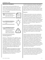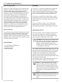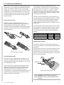
1
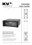
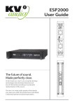
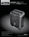
EX1.8
User Guide
The future of sound.
Made perfectly clear.
At KV2 Audio our vision is to constantly develop
technologies that eliminate distortion and
loss of information providing a true dynamic
representation of the source.
Our aim is to create audio products that absorb
you, place you within the performance and deliver
a listening experience beyond expectation.
CONTENTS
USER’S GUIDE
1
CONTENTS
2
INTRODUCTION
HOW TO USE THIS MANUAL
3
3
3
3
3
4
4
4
Icons used include
Introducing the EX1.8
Electronics
Acoustic Components
Enclosure Design
APPLICATIONS
AC POWER REQUIREMENTS
AC POWER
Voltage Requirements
The Power Connector
Current Requirements
AC Cable Color Coding
IMPORTANT SAFETY INSTRUCTIONS
SAFETY SUMMARY
EX1.8 CONTROL PANEL
REAR CONTROL PANEL
Audio Input and Output
Amplifiers and Acoustic Filters
LED Status Lights
Power On / Thermal LED
Signal
Limiter
Phase Switch
Level Control
4
4
4
5
5
5
6
6
7
7
7
8
8
8
8
8
8
8
EX1.8 DRAWING
9
EX1.8 SPECIFICATIONS
10
EX1.8 ACCESSORIES
11
EX1.8 USER’S GUIDE
P. 2
INTRODUCTION
HOW TO USE THIS MANUAL
As you read this manual, you’ll find figures and
diagrams to help you understand and visualize what
you’re reading. You’ll also find numerous icons that
serve as cues to flag important information or warn
you against improper or potentially harmful activities.
Icons used include:
“NOTE” identifies an important or useful piece of
information relating to the
topic under discussion.
“TIP” offers a helpful tip
relevant to the topic at
hand.
“CAUTION” gives notice
that an action can have
serious consequences and
could cause harm to
equipment or personnel,
delays, or other problems.
Introducing the EX1.8
The EX1.8 is a high output, active subwoofer system.
Through the use of proprietary amplifier technology,
a precision manufactured state of the art woofer
component and the innovative implementation of a
high efficiency, twin chamber acoustic design, the
EX1.8 delivers tight, fast, controlled bass response at
very high output levels. This system falls directly out
of KV2 Audio’s philosophy to develop products with
increased dynamic range, very high output and a
consistent sound character no matter what the
output level.
The system establishes new performance standards
for an active powered subwoofer that can only be
achieved through the integration of new amplifier
topologies, transducer designs and electronic control
technologies that are closely tied to a passion for
taking performance to the next level.
EX1.8 USER’S GUIDE
The EX1.8 can be used in a variety of system applications. It can add high performance bass reproduction
to active speaker systems such as KV2 Audio’s EX12
loudspeaker, or it can be easily used with passive
speaker systems. The built in electronic high pass filter,
phase and independent output level controls provide
high precision, easy to use system integration circuitry.
Electronics
Amplifier power, electronic crossovers, equalization
and speaker protection are integrated into the EX1.8’s
amplifier module. On-board electronics ensures fast,
easy set up and complete control making it easy to set
up and provides long-term reliability. An improved
version of KV2 Audio’s switch mode, current enhancing
low frequency amplifier has been specially developed
for the EX1.8 . The new design improves overall system
efficiency to over 90% and delivers 1000 watts of
continuous power.
KV2 Audio has developed an amplifier topology that
possesses two unique characteristics that are critically
important for high performance, active subwoofer
systems. The EX1.8 amplifier topology delivers very
high efficiency and generates minimal thermal losses
allowing the amplifier to deliver extremely high power
levels reliably whilst employing a simple cooling
system.
Secondly, in order to reproduce low frequency information with high transient content and extend the
operational boundaries of the acoustic design, the
amplifier needs to deliver an extraordinary amount of
current in order to keep the woofer’s high mass under
control. This is especially true under typical “phase
shift” conditions, in which the amount of the current
requirement is sometimes doubled. Through the
implementation of a proprietary, switch mode amplifier technology, the EX1.8 amplifier provides extremely
high efficiency with low losses and delivers the highest
woofer control by delivering higher current levels
under “phase shift” conditions.
The amplifier module is fitted onto a large format,
finned, aluminum alloy heat sink providing high flow,
passive cooling and eliminating standard maintenance
cycles associated with forced cooled amplifier designs.
The entire mechanical assembly is fitted on a mechanical suspension system that isolates low frequency
energy and ensures long-term reliability.
P. 3
AC POWER REQUIREMENTS
Acoustic Components
AC POWER
The EX1.8’s woofer technology is based around high
efficiency, high power woofer designs. The device
features: high temperature polymide voice coil
assemblies that undergo multiple baking and curing
processes as well as advanced magnetic structures
with complex cooling systems. The woofer cones
have been specially developed to withstand the
demanding environment created by the high acoustic loading inside the EX1.8 chambers. The EX1.8 was
designed using new concepts in twin asymmetrical
acoustic chambers that deliver very high speaker
loading and output from a relatively small cabinet
footprint. It is ideal for use in live applications that
require reproduction of low frequencies with very
high transient content at high output levels.
The EX1.8 is an advanced self-powered loudspeaker
system with on-board amplification and control
systems. Understanding power distribution, voltage
and current requirements, as well as electrical safety
issues, is critical to the safe operation of the EX 1.8.
5IF&9VTFTB1PXFS$POQPMF"$NBJOTZTUFN
with locking connectors to prevent accidental disconOFDUJPO5IFNBJO"$DPOOFDUPSCMVF
TFSWFTBTUIF
power input.
5IF&9PQFSBUFTJOFJUIFS7PS7NPEFT
"MUIPVHIQSFDPOGJHVSFEBUUIFGBDUPSZUIFVOJUT
operating voltage mode can be changed in the field.
Enclosure Design
Voltage Requirements
There are two industrial grade, internal braces placed
at the top of the cabinet. Each brace is held in place
by four M8 bolt and feature two M10 hang points
providing a wide range of installation and suspension
flexibility. There is also a pole mount “top hat” located
on the top side of the cabinet.
APPLICATIONS
t-JWFBOE1MBZCBDL"QQMJDBUJPOT
t1PSUBCMF1"4ZTUFNT
t$PSQPSBUF&WFOUT
t'JYFE*OTUBMMBUJPOT
The EX1.8 operates safely and without audio discontiOVJUZJGUIF"$WPMUBHFTUBZTXJUIJOUIFPQFSBUJOH
XJOEPXPG77JO7NPEFBOE77
XIFOXPSLJOHJO7NPEFBUPS)[
CAUTION*GUIF0O-&%EPFTOPUJMMVNJOBUFPS
the system does not respond to audio input,
SFNPWF"$QPXFSJNNFEJBUFMZ7FSJGZUIBUUIF
voltage is within the proper range. If the
QSPCMFNQFSTJTUTQMFBTFDPOUBDU,7"VEJPPS
BOBVUIPSJ[FETFSWJDFDFOUFS
If the voltage drops below the low boundary of its safe
operating range, the loudspeaker will shut down if the
voltage does not rise above the low boundary before
TUPSBHFDJSDVJUTBSFEFQMFUFE)PXMPOHUIFMPVEspeaker will continue to function during brownout
depends on the amount of voltage drop and the audio
source level during the drop.
If the voltage increases above the upper boundary of
the range, the power supply can be damaged.
NOTE: It is recommended that the voltage
supply be within the rated voltage window.
5IJTFOTVSFTUIBU"$WPMUBHFWBSJBUJPOTGSPN
the service entry-or peak voltage drops due to
cable runs-do not cause the amplifier to cycle
on and off or cause damage to the power
supply.
NOTE'PSCFTUQFSGPSNBODFUIF"$DBCMF
voltage drop should not exceed 10 volts, or 10
QFSDFOUBUWPMUTBOEQFSDFOUBU
volts..
EX1.8 USER’S GUIDE
P. 4
AC POWER REQUIREMENTS
Make sure that even with the AC voltage drop, the AC
voltage always stays within recommended operating
ranges. The minimum electrical service amperage
required by a EX1.8 speaker system is the sum of each
loudspeaker’s maximum continuous rms current. An
additional 50 percent above the minimum amperage
is recommended to prevent peak volt-age drops at
the service entry.
The Power Connector
The EX1.8 requires a grounded outlet. It is very
important that the loudspeaker AC supply be properly grounded in order to operate safely and
correctly. Use the PowerCon AC cable-wiring diagram
on page 5 to create international or special-purpose
power connectors:
The maximum long-term continuous current
consumption is the maximum rms current during a
period of at least ten seconds. It is used to calculate
the temperature rise in cables, in order to select a
cable size and gauge that conforms to electrical code
standards. It is also used to select the rating for slowreacting thermal breakers.
The burst current consumption is the maximum rms
current during a period of approximately one second,
used to select the rating of most magnetic breakers
and to calculate the peak voltage drop in long AC
cables according to the formula: V pk (drop)= I pk x R
(cable total).
The ultimate short-term peak current is used to select
the rating of fast reacting magnetic breakers. Use the
table below as a guide when selecting cable gauge
size and circuit breaker ratings for your operating
voltage.
Current Draw
Max. Long Term Continuous
Burst Current
Short Term Peak
115 V Mode
10 A rms
15 A rms
40 A peak
230 V Mode
5 A rms
10 A rms
20 A peak
AC Cable Color Coding
Power connector assembly
If the colors referred to in the diagram don’t correspond to the terminals in your plug, use the following
guidelines:
Connect the blue wire to the terminal marked with a N or
colored black. Connect the brown wire to the terminal
marked with an L or colored red. Connect the green and
yellow wire to the terminal marked with an E or colored
green or green and yellow.
Current Requirements
Each EX1.8 requires approximately 10 Amps max at
115V AC for proper operation. This allows one EX1.8
to be powered from one 15 A breaker at 115 V and up
to 2 subwoofers at 230 V.
The EX1.8 presents a dynamic load to the AC mains,
which causes the amount of current to fluctuate
depending on quiet or loud operating levels. Since
different cables and circuit breakers heat up at
varying rates, it is essential to understand the types of
current ratings and how they correspond to circuit
breaker and cable specif cations.
GREEN / YELLOW
Power cable color coding
CAUTION: The EX1.8 requires a ground
connection. Always use a grounded outlet
and plug.
EX1.8 USER’S GUIDE
P. 5
AC POWER REQUIREMENTS
IMPORTANT SAFETY INSRUCTIONS
SAFETY SUMMARY
1. Read all product instructions.
To reduce the risk of electric shock, disconnect the
loudspeaker from the AC mains before installing audio
cable. Reconnect the power cord only after making all
signal connections. Connect the loudspeaker to a
twopole, three-wire grounding mains receptacle. The
receptacle must be connected to a fuse or circuit
breaker. Connection to any other type of receptacle
poses a shock hazard and may violate local electrical
codes. Do not allow water or any foreign object to get
inside the loudspeaker. Do not put objects containing
liquid on or near the unit. To reduce the risk of overheating the loudspeaker, avoid exposing it to direct
sunlight. Do not install the unit near heat-emitting
appliances, such as a room heater or stove. This
loudspeaker contains potentially hazardous voltages.
Do not attempt to disassemble the unit. The unit
contains no user serviceable parts, repairs should be
performed only by factory trained service personnel.
2. Keep printed instructions, do not throw away.
3. Respect and review all warnings.
4. Follow all instructions.
5. Do not use this loudspeaker near water, in unprotected out door areas or in rain or wet conditions.
6. Clean only with dry cloth.
7. Do not block any ventilation openings.
8. Install in accordance with KV2 Audio recommended installation instructions.
9. Do not install near any heat sources such as heat
radiators, heat registers, stoves, or other apparatus
that produce heat.
10. Do not defeat the safety purpose of the grounding type plug. A grounding type plug has two blades
and a third grounding connector. The third connector
is provided for your safety. If the provided plug does
not fit into your outlet, consult an electrician for
replacement of the obsolete outlet.
11. Protect the power cord from being walked on or
pinched, particularly at plugs, convenience receptacles, and the point where they exit from the loudspeaker. The AC mains plug or appliance coupler
shall remain readily accessible for operation.
12. Only use accessories specif ed by KV2 Audio.
13. Install the product only with rigging specified by
KV2 Audio, or sold with the loudspeaker.
CAUTION: Rigging should only be done by
experienced professionals.
14. Unplug this loudspeaker during lightning storms
or when unused for long periods of time.
15. Refer all servicing to qualifed service personnel.
Servicing is required when the loudspeaker has been
damaged in any way, such as when the power-supply
cord or plug has been damaged; liquid has been
spilled or objects have fallen into the loudspeaker;
rain or moisture has entered the loudspeaker; the
loudspeaker has been dropped; or when for undetermined reasons the loudspeaker does not operate
normally.
EX1.8 USER’S GUIDE
P. 6
EX1.8 CONTROL PANEL
REAR CONTROL PANEL
Audio signal can be daisy-chained using the through
output connector on the input panel. A single source
can drive multiple EX1.8 subwoofers with a paralleled
input loop. If you are driving multiple EX1.8’s in an
array, make certain that the source device can drive
the total load impedance presented by the paralleled
input circuit of the array.
The EX1.8 features an easy to use rear control panel
featuring audio input and output connections, level
control, LED status lights and a low pass filter that can
be engaged when the loudspeaker is used as a stage
monitoring device.
Audio Input and Output
NOTE: Most source equipment is safe for
driving loads no smaller than 10 times the
source’s output impedance. For example,
cascading an array of 10 units consisting of
EX1.8 subwoofers produces an input impedance of 2000 ohms (20kOhms divided by 10).
The source equipment should have output
impedance of 200 ohms or less. This is also
true when connecting EX1.8’s in parallel (loop
out) with other KV2 Audio amplifiers, active
speakers and subwoofers.
The EX1.8 uses balanced, female XLR connectors for
audio signal input, and a male XLR connector to
provide through output signal. The EX1.8 features
Left and Right stereo inputs and outputs allowing the
product to be integrated into stereo systems that
require one subwoofer.
The EX1.8 also features Left and Right High Pass
Outputs that can be used to provide audio signal to
full range speakers being used in conjunction with
the EX1.8. The high pass filter provides a crossover
point of 125Hz.
TIP: If the loudspeaker produces noises such
as hiss and popping, disconnect the audio
cable from the loudspeaker, if the noise stops,
then most likely the problem is not with the
loudspeaker. Check the audio cable, source,
and AC power for the source of the problem.
The through output connector, wired in parallel to
the audio input, will continue to provide the input
signal if the EX1.8 is turned off. The audio input circuit
presents a 20 kOhm balanced input impedance to a
three-pin XLR connector with the following connectors:
Main input
NOTE: Ensure that all cabling carrying signal
to multiple amplifiers and active speaker
systems is wired correctly. Make sure that the
polarity has not been reversed. Reversed
polarity can cause severe degradation in
frequency response and can also impact the
dispersion characteristics of the speaker.
Through output
Pin 1 - Ground
Pin 2 - Signal (+)
Pin 3 - Signal (-)
Case - Earth (AC) ground and chassis
L
230 VAC 50/60 Hz
1200 WATTS
SIGNAL PRESENT
SIGNAL PRESENT
POWER ON/
THERMAL
LEVEL
THROUGH OUTPUT
ON
WARNING:
RISK OF ELECTRIC SHOCK
DO NOT OPEN
0
LIMITER
R
THROUGH OUTPUT
CAUTION
PHASE
AVIS:
RISQUE DE CHOC ELECTRIQUE
NE PAS OUVRIR
WARNING: THIS SURFACE MAY REACH HIGH TEMPERATURE DURING STANDARD USE.
TO ENSURE PROPER OPERATION ALLOW A MINIMUM OF 6 INS. OF CLEARANCE FROM
THIS SURFACE AND ADEQUATE VENTILATION. TO REDUCE THE RISK OF ELECTRIC SHOCK
DO NOT REMOVE THIS PANEL OR ANY ATTACHED COMPONENT. NO OPERATOR SERVICEÐ
ABLE PARTS INSIDE. REFER SERVICING TO QUALIFIED PERSONNEL. TO REDUCE THE RISK
OF FIRE OR ELECTRIC SHOCK, DO NOT EXPOSE THIS APPLIANCE TO RAIN OR MOISTURE.
DESIGNED BY KV2 AUDIO, MANUFACTURED IN THE CZECH REPUBLIC
-6dB
OFF
SERIAL NUMBER
MAIN INPUT
HIGH PASS OUTPUT
REVERSE 180°
+ 6dB
NORMAL 0°
HIGH PASS OUTPUT
MAIN INPUT
WWW.KV2AUDIO.COM
EX1.8 Rear panel
EX1.8 USER’S GUIDE
P. 7
EX1.8 CONTROL PANEL
Amplifiers and Acoustic Filters
Phase Switch
A power amplifier specifically designed and
optimized for the low frequency woofer powers the
EX1.8 . The control system in the EX1.8 processes the
audio signal through a series of electronic filters and
circuits providing equalization, crossover filters,
thermal and overdrive protection.
The EX1.8 features a phase switch that changes the
phase of the high pass audio output signal. Changing
the phase of the output signal serves as a tool for
integrating the full range cabinet and the subwoofer
into challenging audio environments. We recommend
using a suitable measuring device for performing
relevant measurements and determining whether the
phase should be reversed.
LED Status Lights
The EX1.8 control panel uses three distinct LED’s to
provide operating status information.
Power On / Thermal LED
This LED turns green when the speaker is turned ON.
The light will continue to be green during normal
operation of the speaker system. The LED will change
from green to yellow under a thermal condition
resulting from overheating of the amplifier system.
Under this condition, the speaker system will shut
down. You can expect for the system to be down for
at least 2-3 minutes depending the ambient temperature and whether the system is being exposed to
direct sun light.
Level Control
The EX1.8 features a rotary control knob providing
adjustment of the audio level. The operational range of
the control is –6dB to +6dB.
Signal
There are individual LED’s for each the Left and Right
signal inputs. The LED turns green when there is
audio signal present in the EX1.8. This signal indicator
can be used to troubleshoot wiring problems.
Limiter
Should the rms limiting system be engaged due to
overdriving of the EX1.8, the LED will light up yellow.
The audible effect of the rms limiter is a lowering of
overall output level. The rms limiter will disengage
only if the input level is turned down.
NOTE: Please contact KV2 Audio or a local
service representative should the system
enter a thermal condition under normal
operating conditions.
EX1.8 USER’S GUIDE
P. 8
EX1.8 DRAWING
EX1.8 USER’S GUIDE
P. 9
EX1.8 SPECIFICATIONS
Product Number
KVV 987 223 - EX1.8 250V
KVV 987 007 - EX1.8 230V
KVV 987 008 - EX1.8 115V
System Acoustic Perfomance
Max SPL Long-term
Max SPL Peak
-3dB Response
-10dB Response
Crossover Point
131dB
134dB
30Hz - 125Hz
27Hz - 125Hz
125Hz
Low Frequency Section
Acoustic Design
Woofer Size / Voice Coil Diameter/ Design
Diaphragm Material
Magnet Type
Twin Asymmetrical loading
18" / 4" / Inside outside
Epoxy Reinforced Cellulose
Neodymium
Low Frequency Amplifier Specification
Type
Rated Continuous Power
Distortion
High efficiency, Current-enhancing switch mode
1000W
<0.05%
Signal Input
Input Sensitivity
Input Impedance
1.0V RMS
20 kΩ
Power Requirements
Power Connector
Operating Voltage
Recommended Amperage
Neutrik PowerCon®
100 - 120V @ 60Hz | 205 - 240V @ 50Hz | 225 - 260V @ 50Hz
10A 115V | 5A 230V | 5A 250V
Cabinet
Cabinet Material
Handles
Pole Mount
Color
Baltic birch
2
M20
Black
Physical Dimensions
Height
Width
Depth
Weight
EX1.8 USER’S GUIDE
612.1mm (24.1")
700mm (27.56")
750mm (29.5")
65kg (143.3lbs)
P. 10
EX1.8 ACCESSORIES
Heavy duty cover for EX1.8 used
without cart
part name: COVER EX1.8
part number: KVV 987 258
Front mount magnetic cart for
EX1.8
part name: CRT - 0011
part number: KVV 987 230
- wheels not included
Heavy duty cover for EX1.8 used
with cart CRT - 0011
part name: COVER EX1.8 WITH CART
part number: KVV 987 257
Cart Wheels with bolts nuts kit
part name: CRT - WHL
part number: WHL - KVV 987 031
- 4 pcs in pack (rotating), (blue)
Heavy duty telescopic speaker
pole for ES/EX series
part name: KV2-H
part number: KVV 987 130
EX1.8 USER’S GUIDE
P. 11
The future of sound.
Made perfectly clear.
At KV2 Audio our vision is to constantly develop
technologies that eliminate distortion and
loss of information providing a true dynamic
representation of the source.
Our aim is to create audio products that absorb
you, place you within the performance and deliver
a listening experience beyond expectation.
KV2 Audio, Nádražní 936, 399 01 Milevsko, Czech Republic
T +44(0)1423 816868 F +44(0)1423 816869
www.kv2audio.com
KVV120006-00-02-0