1
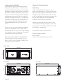
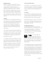
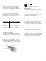
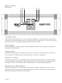
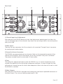
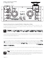
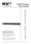
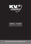
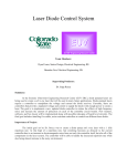
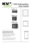
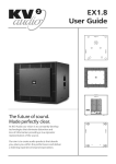
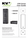
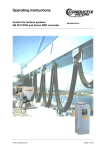
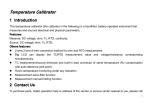
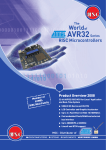
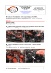
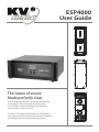
ESP4000
User Guide
The future of sound.
Made perfectly clear.
At KV2 Audio our vision is to constantly develop
technologies that eliminate distortion and
loss of information providing a true dynamic
representation of the source.
Our aim is to create audio products that absorb
you, place you within the performance and deliver
a listening experience beyond expectation.
Contents
Warranty
Your ESP4000 is covered against defects in material
and workmanship. Refer to your supplier for more
details.
Service
In the unlikely event that your ESP4000 develops a problem, it must be returned to an authorised distributor,
service centre or shipped directly to our factory.
Because of the complexity of the design and the risk of
electrical shock, all repairs must be attempted only by
qualified technical personnel. If the unit needs to be
shipped back to the factory, it must be sent in its original carton. If improperly packed, the unit may be damaged. To obtain service, contact your nearest KV2
Audio Service Centre, Distributor or Dealer.
Page | 2
Introduction
How to use this manual
Icons used include
Important Safety Instructions
Introducing the ESP4000
Dimensions
3
3
3
4
4
Chapter 2: Getting Started
Unpacking
Rack Mounting
Cooling
AC Power Requirements
AC Power
Voltage Requirements
The Power Connector
Current Requirements
AC Cable Colour Coding
Safety Summary
4
5
5
5
5
5
6
6
7
7
Chapter 3: Features
Front Panel
Rear Panel
8
9
Chapter 4: Running the ESP4000 in
“Bridge Mono” Mode
10
ESP4000 Specifications
11
How to use this manual
As you read this manual, you’ll find figures and
diagrams to help you understand and visualise
what you’re reading. You’ll also find numerous
icons that serve as cues to flag important information or warn you against improper or potentially
harmful activities.
Icons Used Include
“NOTE” identifies an
important or useful piece
of information relating to
NOTE
the topic under discussion.
TIP
“TIP” offers a helpful
tip relevant to the topic
at hand.
consult an electrician for replacement of the
obsolete outlet.
11. Protect the power cord from being walked
on or pinched, particularly at plugs, convenience receptacles and the point where they exit
from the amplifier. The AC mains plug or appliance coupler shall remain readily accessible for
operation.
12. Only use accessories specified by KV2 Audio.
13. The unit is intended for use in a 19” rack.
Follow the mounting instructions. When a rack on
wheels is use, use caution when moving the loaded
rack to avoid injury from tipping over.
14. Install the product only with both front and
rear supports.
!
CAUTION
!
CAUTION
“CAUTION” gives notice
that an action can have
serious consequences and
could cause harm to
equipment or personnel,
delays, or other problems.
Important Safety Instructions
1 Read all product instructions.
2. Keep printed instructions, do not throw away.
3. Respect and review all warnings.
4. Follow all instructions.
5. Do not use this unit near water, in unprotected
out door areas or in rain or wet conditions.
6. Clean only with dry cloth.
7. Do not block any ventilation openings.
8. Install in accordance with KV2 Audio’s
recommended installation instructions.
9. Do not install near any heat sources such as heat
radiators, heat registers, stoves or other apparatus
that produce heat.
10. Do not defeat the safety purpose of the grounding type plug. A grounding type plug has two
blades and a third grounding connector. The third
connector is provided for your safety. If the provided
plug does not fit into your outlet,
Installation should only be
done by experienced professionals.
CAUTION:
15. Unplug this amplifier during lightning
storms or when unused for long periods of time.
16. Do not connect a ESP4000’s output in parallel
or series with any other ESP4000’s output. Do not
connect the ESP4000 output to any other voltage
source, such as a battery, mains source or power
supply, regardless of whether the ESP4000 is
turned on or off.
17. Do not run the output of any ESP4000 back
into another channels input.
18. Refer all servicing to qualified service personnel. Servicing is required when the amplifier
has been damaged in any way, such as when
the power-supply cord or plug has been damaged; liquid has been spilled or objects have
fallen into the amplifier; rain or moisture has
entered the amplifier; the amplifier has been
dropped; or when for undetermined reasons
the amplifier does not operate normally.
19. Do not remove top or bottom covers.
Removal of the cover will expose hazardous
voltages. There are no user serviceable parts
inside and removable may void the warranty.
20. An experienced user shall always supervise
this professional audio equipment.
Page | 3
Introducing the ESP4000
The ESP4000 is a four channel rack mountable power amplifier. The unit contains four
seperate 1000 watt amplifiers, two independent power supplies (two channels running off
each power supply) signal paths, inputs and
outputs as well as limiting and low frequency
enhancement on each of the four channels
within a four rack unit chassis. It can be used
to power a range of passive loudspeakers as
well as being specifically designed for optimised performance with KV2 Audio’s ESD
Series.
Whilst this unit is simple to operate improper
use can be dangerous. This is a very highpowered device that can put out high voltages
and sizeable currents. Always use safe operating techniques with the ESP4000.
FOR YOUR SAFETY, READ THE IMPORTANT
PRECAUTIONS SECTION AS WELL AS THE
INPUT, OUTPUT AND POWER CONNECTION
SECTIONS OF THIS MANUAL.
Chapter 2: Getting Started
Unpacking
Unpack the ESP4000 and check to see if
there is any damage to it. If you find any damage notify your supplier immediately. Only the
consignee may institute a claim with the carrier for any damage incured during shipping. Be
sure to save the carton and all packaging
materials for the carrier’s inspection.
Should you ever need to ship the unit, only
use the original factory packaging. If the shipping carton is unavailable, contact your supplier to obtain a replacement.
The ESP4000 carton should contain:
ESP4000 power amplifier
User’s manual
2x PowerCon detachable power cable
FRONT PANEL
481,4 mm
CH
177 mm
POWER /
THERMAL
SIGNAL /
LIMITER
LIMITER
+BASS
REAR PANEL
SIDE PANEL
415,4 mm
431.8 mm
1
-6dB
1
0dB
min. 2
250 VAC
177 mm
-6dB
2
230 VAC
0dB
2
115 VAC
min. 2
-6dB
3
3
0dB
min. 2
SERIAL NUMBER
-6dB
4
4
0dB
WWW.KV2AUDIO.COM
DESIGNED BY KV2 AUDIO
MANUFACTURED IN THE EUROPEAN UNION
Page | 4
min. 2
Rack Mounting
ESP4000’s will mount in standard 19” rack
systems. Integral rear mounting rack ears are
also provided for additional support. It is
important that you do not rely on fixing and
mounting the ESP4000 using just the front
panel as support. Use eight screws and washers to mount the amplifier to the equipment
rack rails (four for the fronts and four for the
rear). We recommend using a shock mounted
rack for touring use to prolong the life of your
ESP4000.
Cooling
The ESP4000 has a comprehensive cooling system featuring chassis-sealed PCB board mounting and shock mounted, speed controlled fans.
This means that the cooling system never
drives air across PCB boards, connectors or
components ensuring prolonged electronic
component lifespan and minimizing maintenance cycles.
Air is drawn into the front of the amplifier by
the two fans on the rear panel, this passes over
the cooling fins of the heat sinks and exhausts
through the rear. If the heat sink gets too hot,
its sensing circuit will open the output relay,
disconnecting the load.
It is important to have an adequate air supply
at the front of the amplifier, and enough space
around the rear of the amplifier to allow the
cooling air to escape. If the unit is rack-mounted, do not use doors or covers on the rear of
the rack; the exhaust air must flow without
restriction. If you are using racks with closed
backs, use fans on the rear rack panel to
ensure an ample air supply.
AC Power Requirements
The ESP4000 is an advanced power amplifier.
Understanding power distribution, voltage and
current requirements, as well as electrical safety
issues, is critical to the safe operation of the
ESP4000.
AC Power
The ESP4000 uses a pair of PowerCon 3-pole
AC main systems with locking connectors to
prevent accidental disconnection. The main AC
connectors (blue) serve as the power inputs.
The ESP4000 operates in either 115V, 230V or
250V modes. Although pre-configured at the
factory, the unit’s operating voltage mode can
be changed in the field.
Voltage Requirements
The ESP4000 operates safely and without
audio discontinuity if the AC voltage stays within the operating window of 100V-130V in
115V mode, 200V-250V when working in
230V mode and 220-270V when working in
250V mode at 50 or 60Hz.
If the On LED does not
illuminate or the system does not
CAUTION
respond to audio input, remove AC
power immediately. Verify that the voltage is
within the proper range. If the problem persists,
please contact KV2 Audio or an authorized
service center.
!
CAUTION:
If the voltage drops below the low boundary of
its safe operating range, the amplifier will shut
down if the voltage does not rise above the low
boundary before storage circuits are depleted.
How long the amplifier will continue to function
during brownout depends on the amount of
voltage drop and the audio source level during
the drop. If the voltage increases above the
upper boundary of the range, the power supply
can be damaged.
Page | 5
It is recommended that the
voltage supply be within the rated
NOTE
voltage window. This ensures that
AC voltage variations from the service entry or peak voltage drops due to cable runs - do
not cause the amplifier to cycle on and off or
cause damage to the power supply.
NOTE:
NOTE: For best performance, the AC
cable voltage drop should not exceed
10 volts, or 10 percent at 115 volts
and 5 percent at 230 volts.
NOTE
Make sure that even with the AC voltage drop,
the AC voltage always stays within recommended
operating ranges. The minimum electrical service
amperage required by an ESP4000 amplifier is
the sum of each amplifiers maximum continuous rms current. An additional 50 percent above
that amperage is recommended to prevent peak
voltage drops at the service entry.
The Power Connector
The ESP4000 requires grounded outlets. It is
very important that the amplifiers AC supply
be properly grounded in order to operate
safely and properly. Use the PowerCon AC
cable-wiring diagram overleaf to create international or special-purpose power connectors:
Page | 6
Current Requirements
Each of the ESP4000’s power supply inputs
require approximately 20 Amps max at 115V AC
for proper operation. This means that both of the
ESP4000’s power supplies must be powered from
an individual 20 A breaker when running in 115V
mode.
When operating in 230 V mode each of the ESP
4000’s power supply inputs requires approximately 10 Amps max. This allows a complete ESP4000
to be powered from one 20 A breaker at at 230
V.
The ESP4000 presents a dynamic load to the
AC mains, which causes the amount of current to
fluctuate depending on quiet or loud operating
levels. Since different cables and circuit breakers
heat up at varying rates, it is essential to understand the types of current ratings and how they
correspond to circuit breaker and cable specifications.
The maximum long-term continuous current is the
maximum rms current during a period of at least
ten seconds. It is used to calculate the temperature rise in cables in order to select a cable size and
gauge that conforms to electrical code standards.
It is also used to select the rating for slow-reacting
thermal breakers.
The burst current is the maximum rms current
during a period of approximately one second,
used to select the rating of most magnetic
breakers and to calculate the peak voltage
drop in long AC cables according to the formula:
V pk (drop)= I pk x R (cable total)
The ultimate short-term peak current is used
to select the rating of fast reacting magnetic
breakers. Use the table below as a guide
when selecting cable gauge size and circuit
breaker ratings for your operating voltage.
Current Draw per Power Supply Input
Current Draw
115V Mode
230V Mode
Max Long Term
Continuous
20 A rms
10 A rms
Burst Current
30 A rms
15 A rms
Short Term Peak
80 A peak
40 A peak
AC Cable Colour Coding
If the colours referred to in the diagram don’t
correspond to the terminals in your plug, use
the following guidelines: Connect the blue wire
to the terminal marked with an N or coloured
black. Connect the brown wire to the terminal
marked with an L or coloured red. Connect
the green and yellow wire to the terminal marked
with an E or coloured green or green and yellow.
!
CAUTION
The ESP4000 requires a
ground connection. Always use
a grounded outlet and plug.
CAUTION:
Safety Summary
To reduce the risk of electric shock, disconnect
the amplifier from the AC mains before
installing audio cable. Reconnect the power
cord only after making all signal connections.
Connect the amplifier to a two pole, threewire grounding mains receptacle.
The receptacle must be connected to a
fuse or circuit breaker. Connection to any
other type of receptacle poses a shock
hazard and may violate local electrical codes.
Do not allow water or any foreign object
to get inside the amplifier. Do not put objects
containing liquid on or near the
unit. To reduce the risk of overheating the
amplifier, avoid exposing it to direct
sunlight. Do not install the unit near heatemitting appliances, such as a room heater
or stove. This amplifier contains potentially
hazardous voltages. Do not attempt to
disassemble the unit. The unit contains no user
serviceable parts, repairs should be performed
only by factory trained service personnel.
Page | 7
Chapter 3: Features
Front Panel
1 2 3
4 5
1) AC Mains Switch
The ESP4000 has combination AC mains switch/circuit breakers on the front panel. If either of the
switches shuts off during normal use, push it back to the ON position once. If it will not stay on you
should take the unit to qualified service personnel to have it serviced.
2) +Bass Switch
When depressed this switch activates a bass enhancement feature that increases the chosen channels output by 6dB at 60Hz
3) Limiter Switch
The ESP4000 features RMS limiting on each channel. This feature is active so long as the switch is
left un-pressed. The RMS limiting is deactivated when the switch is depressed.
4) Power On / Thermal
These are dual colour LED’s. When green they indicate that the Power Switch is ON and that channel of the amplifier is powered up. When red they indicate that that channel has overheated and
shut down. The unit will Auto Reset after it cools down to a safe operating temperature.
5) Signal Present / Limiter Indicator
These are dual colour LED’s. When green they indicate that signal is present at the Input to that
particular channel of the amplifier. When yellow they indicate that the audio limiter has been activated for that particular channel of the amplifier.
Page | 8
Rear Panel
1
2
3
4
1
-6dB
1
5
0dB
min. 2
250 VAC
-6dB
2
230 VAC
0dB
2
115 VAC
min. 2
-6dB
3
3
0dB
min. 2
SERIAL NUMBER
-6dB
4
4
0dB
WWW.KV2AUDIO.COM
DESIGNED BY KV2 AUDIO
MANUFACTURED IN THE EUROPEAN UNION
min. 2
1) Channel Input Level Adjustment
Each channel of the ESP4000 features an Input Level adjustement potentiometer that allows the
user to individually adjust all four channel’s input levels from oo through -6dB in the vertical position
and up to to 0dB.
2) Main Inputs
These are the input connectors for all four channels with associated ‘Through Output’ connectors
for sending signal to other devices.
3) PowerCon Power Connectors
The ESP4000 uses one connector per two channels. Both must be connected to operate all four
channels of the ESP4000. Half of the channels will be fully functional if only one is connected.
They accept standard PowerCon terminated AC Mains cables.
4) Fans
The cooling fans operate continuously while the ESP4000 is on. An internal temperature sensor
increases the speed of the fans during high temperature conditions. Air enters through the front
grille and exits through the rear. Be sure to allow adequate air flow to the front of the rack in which
the ESP4000 is mounted.
5) Main Outputs
Each channel of the ESP4000 is equipped with binding posts and Neutrik Speakon® connectors on
the Main Outputs. The minimum recommended output is 2W.
Page | 9
4ohm 1800W
Chapter 4: Running the ESP4000
in “Bridge Mono” Mode
PHASE REVERSE CABLE
+
SIGNAL INPUT
1
-6dB
1
0dB
min. 2
250 VAC
-6dB
2
230 VAC
2
115 VAC
0dB
min. 2
-6dB
3
3
0dB
min. 2
SERIAL NUMBER
-6dB
4
4
0dB
WWW.KV2AUDIO.COM
DESIGNED BY KV2 AUDIO
MANUFACTURED IN THE EUROPEAN UNION
min. 2
Input level potentiometers of each bridged channel must be set to the same level. Channels 3 and 4 can also be used in the same way to achieve the same ends.
Important Information for using the ESP4000 in “Bridge Mono” Mode
As well as being a high quality multi channel amplifier solution the ESP4000 is capable of working in “Bridge Mono” mode.
This requires the utilisation of two channels working together to produce a larger single output - suitable for driving large subwoofers or high powered full range boxes.
!
CAUTION
CAUTION: YOU CAN ONLY BRIDGE OUTPUTS 1 & 2 OR OUTPUTS 3 & 4. ATTEMPTING TO BRIDGE OUTPUTS
1 & 3 OR 2 & 4 COULD CAUSE SERIOUS AND PERMANENT DAMAGE TO THE AMPLIFIER AND THE LOAD.
To do this you must take the positive output from CH1 (RED) and feed the positive side of the high powered loudspeaker loud.
You must then take the positive output from CH2 (RED, situated directly below CH1’s positive red terminal) and feed the negative side of the high powered loudspeaker load.
This has correctly connected the high powered loudspeaker load to both CH1 & CH2 ready to be driven in Bridge Mono mode.
To ensure the amplifier channels are working together correctly in this mode you must feed the Main Input Signal into ONLY
CH1 before linking across to CH2 with a special phase reversal lead. To make this lead you must modify a standard XLR patch
cable so that pins 2 and 3 (Hot and Cold) are swapped AT ONE END ONLY. This results in Pin 2+ at one end going to Pin 3at the other. The Through Output of CH1 should then be connected to the Main Input socket of CH2 using ONLY THE PHASE
REVERSED CONNECTION LEAD.
The same can be done with CH3 & CH4 to provide two independent Bridge Mono amplifiers capable of delivering 1800W per
channel into 4ohms.
NOTE: If Bridge Mono is your specific requirement, particularly driving subwoofers, you may prefer to utilise a KV2
Audio VHD3200 subwoofer amplifier which will of fer the same power output but with improved performance. For
NOTE
applications where the high powered loudspeaker load is required to produce a full range signal, including Mid and
High frequency reproduction above 1kHz an ESP4000 will offer superior results.
Page | 10
System Acoustic Perfomance
-1dB Response
Channel Crosstalk
Signal to Noise Ratio
Total Harmonic Distortion
3Hz ÷ 40kHz
>60dB
>115dB
<0.005% (1W) / <0.01% (clip -1dB)
Output Channels
Amplifier Type
Number of Channels
Total Output Power
Max. Output Voltage
Max. Output Current
Minimum load impedance per channel
Out. Power 16Ω - 1 channel / 2 channels loaded
Out. Power 8Ω - 1 channel / 2 channels loaded
Out. Power 4Ω - 1 channel / 2 channels loaded
Out. Power 2Ω - 1 channel / 2 channels loaded
Out. Power 16Ω - bridged
Out. Power 8Ω - bridged
Out. Power 4Ω - bridged
High efficiency, Emitter coupled
4
4000W
78V (peak)
48A (peak)
2Ω
175W / 160W (RMS)
340W / 300W (RMS)
600W / 500W (RMS)
1000W / 800W (RMS)
600W (RMS)
1000W (RMS)
1600W (RMS)
Speaker Input
Speaker Input
- / 4x Binding posts, Neutrik Speakon®
Signal Input
Input Channels
Input Sensitivity
Input Impedance
Signal Output
XLR
1.55V
20kΩ (balanced)
XLR Through
Features
Level Control
Loudness bass enhancement
RMS Limiter
Indicators
-∞ ÷ 0dB
+6dB @ 60Hz
On / Off
Power ON/Thermal, Signal/Limiter
Power
Power Connector
Operating Voltage
Operating Voltage Range
Recommended Amperage
Soft Start
Protection
Cooling
2x Neutrik PowerCon®
115V / 230V / 250V
100÷120V@60Hz | 205÷240V@50Hz | 225÷260V@50Hz
2x20A 115V | 2x10A 230V | 2x10A 250V
YES
Thermal breaker
2x temperature controlled fans
Physical Dimensions
Height
Width
Depth
Weight
177.8mm (7.0"), 4RU
483mm (19.00")
495mm (19.5")
37,5kg (82.7lbs)
ESP 4000
Specifications
Page | 11
The future of sound.
Made perfectly clear.
At KV2 Audio our vision is to constantly develop
technologies that eliminate distortion and
loss of information providing a true dynamic
representation of the source.
Our aim is to create audio products that absorb
you, place you within the performance and deliver
a listening experience beyond expectation.
KV2 Audio, Nádražní 936, 399 01 Milevsko, Czech Republic
T +44(0)1423 816868 F +44(0)1423 816869
www.kv2audio.com
KVV120054-00-03-0