1
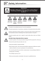
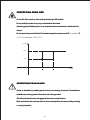
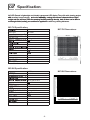
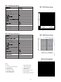
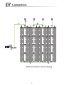
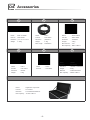
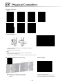
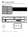
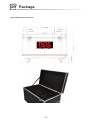
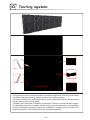
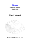
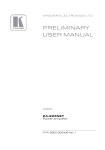
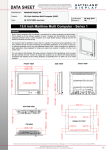
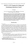
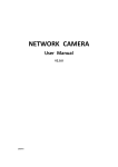
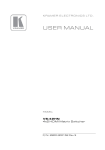
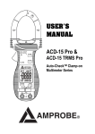
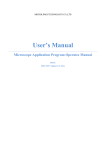
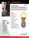
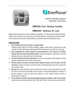
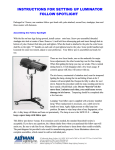
User Manual
MC-7H/9H/12H/18H
-1-
Contents
Safety Information
3
Specification
6
Connection
8
Accessories
9
Header Assembly
11
Physical Connection
12
Control System
13
Service and Maintance
14
Package
15
Tour Frame
16
-2-
01
Safety Information:
WARNING!
Read the safety precautions in this section before
installing, powering, operating or servicing this
product.
The following symbols are used to identify important safety information on the product and in this manual:
WARNING!
WARNING!
WARNING!
WARNING!
Safety hazard.
Refer to
Hazardous Hot surface. Do
Risk of severe manual before voltage. Risk of
not touch.
injury or death.
installing,
lethal or severe
powering or
electric shock.
servicing.
WARNING!
Fire hazard.
WARNING!
Emission
hazardous to
eyesight.
This product is for professional use only. It is not for household use.
This product presents risks of severe injury or death due to fire hazards, electric shock and falls.
Read this manual before installing, powering or servicing this product, follow the safety precautions listed below and observe all warnings in this manual and printed on the product.
If you have questions about how to operate the panel safely, please contact your Radiant
supplier.
PROTECTION FROM ELECTRIC SHOCK
· Connect the product to AC mains power within the range 100-240V nominal at 50 or 60 Hz only.
· Disconnect the product from power when not in use.
· Always ground (earth) the product electrically.
· Before using the product, check that all power distribution equipment and cables are in perfect
condition and rated for the current requirements of all connected devices.
· Do not use the product if the power cable or a power plug is in any way damaged, defective or
showing signs of overheating.
· Do not attempt to open any cover.
· Refer any service operation not described in this manual to a qualified technician.
-3-
PROTECTION FROM FIRE
Do not stick filters, masks or other materials directly onto LED modules.
Do not modify the product in any way not described in this manual.
Install only genuine Radiant parts in or on the product unless an alternative is described in this
manual.
Do not operate the product full load if the ambient temperature of power units (T
(Ta) exceeds 45℃
℃
(113° F) or less than -20℃(-4° F)
Pout/W
2000
1480
165+5
170+5
Vin/Vac
PROTECTION FROM INJURY
Create an installation by installing panels at the top and working downwards. Disassemble an
installation by removing panels at the bottom and working upwards.
Check that all external covers and rigging hardware are securely fastened.
Block access below the work area and work from a stable platform whenever installing, servicing
or moving the product.
-4-
Important warnings
Maximum and minimum ambient temperature:
The maximum ambient temperature for the LED wall is 45 °C; the minimum tem-perature is -20 °C.
High leakage current:
The combination of power boxes in an installation results in increased levels
of Leakage current. In order to avoid risk of electric shock due to high leakage
current, proper grounding of the installation is required.
This equipment MUST be earthed:
In order to protect against risk of electric shock, the installation should be properly grounded. Defeating the purpose of the grounding type plug will expose you
to the risk of electric shock.
Power system
Mains cords:
The power cords delivered with this system have special properties for safety.
They are not user Serviceable. If the power cords are damaged, replace them
only with new ones. Never try to repair a power cord.
Data cables:
The data cables provided with this system have special properties for safety.
They are not user serviceable. If the data cables are damaged, replace them
only with new ones. Never try to repair a data cable. Per requirements of the
National Electrical Code® in the USA, the length of a data cable must not
exceed 100 m (332 feet). Avoid exposure of data cables to accidental contact
with lightning or power conductors.
MC LED Panels cannot be hot swapped:
Always disconnect the power cord from the control box before connecting or
disconnecting the cable string or one of MC LED Panels.
-5-
02 Specification:
MC LED Panels is lightweight and virtually transparent LED display.They offer wide viewing angles
with excellent image integrity and color uniformit
uniformity, owning the common characteristics of light weight and firm structure. With the amazing flexibility and high density, both of them can be able to
multi-angle folded, satisfy your solution for applications
applications with long viewing distances.
MC-7H Specification:
MC-7H Dimensions:
7.5mm
LED Type
3in1 SMD
m2
Cree 3435,6000/NationStar3535,6000
7%
600.0×600.0×82.5
m2
80×80
17778
160°
9.0kg/19.84lbs
S
Area
m2
H
Module
IP(Front/Reverse)
Scan
1/5
1800Hz
Module
Working Temperature
360W
-20 to 45℃
MC-9H Specification:
MC-9H Dimensions:
9.375mm
LED Type
3in1 SMD
m2
S
Area
m2
H
Module
Cree 3435,6000/NationStar3535,6000
17%
600.0×600.0×82.5
m2
64×64
11378
160°
8.05kg/17.75lbs
IP(Front/Reverse)
Scan
1/4
3500Hz
Module
Working Temperature
360W
-20 to 45℃
-6-
MC-12H Specification:
MC-12H Dimensions:
12.5mm
LED Type
3in1 SMD
m
2
Cree 3435,6000/NationStar 3535,6000
21%
S
600.0×600.0×82.5
m2
48×48
6400
160 °
Area
m2
H
Module
7.50kg/16.53lbs
IP(Fron t/Reverse)
Scan
Static
4000Hz
Module
Working Temperature
360W
-20 to 45℃
MC-18H Specification:
MC-18H Dimensions:
18.75mm
LED Type
3in1 SMD
m
2
S
Area
m2
H
Module
Cree 3435,5000/NationStar 3535,4800
37%
600.0×600.0×82.5
m2
32x32
2844
160 °
7.25kg/15.98lbs
IP(Front/Reverse)
Scan
Static
4000Hz
Module
Working Temperature
360W
-20 to 45℃
Backside diagram
Note:
A. Holder
B. Arc connector-rotation angles
C. Horizontal lock
D. Button-Fix the arc
E. Horizontal connector
F. Down Magnet system
G. Self-checking button
I. Signal Socket outlet
J. Power Socket outlet
k. Up Magnet system
L. Breather valve
M.Power supply pin socket
N.Carrying handle
O.Power supply subassembly
-7-
03 Connection:
MC-H Series Built in Power Supply
-8-
04 Accessories
1
Name
2
: Main controller
: SDR-30001
Part No.
Dimesion : L460 x W215 X H40mm
Weight
: 1.48kg
3
: CAT-5
: CAT-30003
Name
Part No.
: Power Cable
: PWC-30001
Dimesion
: 30000mm
Weight
: 30000mm
: 1.4kg
Weight
: 4.6kg
Max Length
: 100000mm
Max Current
: 16A
Name
Part No.
Dimesion
Max Capacity : 8tiles of MC-H
4
5
6
Part No.
: Header
: RIG-06022
Dimesion
: L600xW171xH53mm
Weight
: 3.4kg
: Cold Rolled Steel
Name
Name
Part No.
: CAT-5
: CAT-00912
Dimesion
: 910mm
Material
Weight
: 0.1kg
Max Capacity : 30tiles of MC-H
Name
Part No.
Part No.
: Flightcase 12pcs/case
: FLS-03001
Dimesion
: L1300xW720xH860mm
Name
Max Capacity : 12 tiles of MC-H
-9-
: CAT-5
: CAT-00001
05 Header Assembly:
Standard Header:
Figure 1: Clamp
156.88
Figure 2: Headers
171.10
600.00
- 10 -
Figure 1: Straight installation
Step 1: Match the holes in straight line.
Step 2:Turn the knob and fit securely.
Step 3:Push the bolt in.
Note: Adjust the height of header with the pulley.
Figure 2: Arc installation
Step 1: Match the holes in the angle.
Step 2: Turn the knob and fit securely.
Figure 3: The function of ring
Note: The ring suggest to be used in big show, special stage design, high level background
display…
Headers suggest be used in car show, TV show…some close view distance display.
The ring is not included in standart accessary rist.
- 11 -
06 Physical Connection:
Straight installation
Step1:
Step2:
Curve Installation
1. Loosen the knob and buttons on the header and panels.
2. Adjust the angle.
3. Tighten the knob and bottom.
Note:
Headers can reach the angle of 50°both front and back direction.
Panels can reach the angle of 40°.
For perfect visual effect,seamless curveable is 15°(Both front/back direction).
MC-H&MC-F&Hybrid mixing using
Hollow-design
1. Install all the panels securely.
2. Loosen six buttons and take down the panel.
3. Connect the cables above and below nearby.
Note :Depending on unified frame structure,all of
MC families and hybrid can be integrated
together.
- 12-
07
Control System:
The control system of MC-H series consist of receiving card and sending card.Receiving
card is integated with LED panels.
Working v oltage
100-240V AC
Power
< 10W
Working temperature
-20℃~ 45℃
Input port
DVI
Output ports number
2 ports
Communication port
USB/RJ45
Max resolution
1280x1024
Data transmission port
1000M Ethernet
Material
SPCC
Dimension
L460x W215x H40mm
Weight
1.48kg
Main controller (SDR-30001)
1
2
Front
UP
3
DOWN
4
5
A
B
Behind
1. Nixie tube
2. Switch
3. Power port
4. CAT port
5. USB port
6. DVI Input
1280
1024
Software:
Please read software manual or download from the link as below:
- 13 -
6
Power
08 Service and Maintance:
Figure 1 : Maintenance on overall
installation
Li n
x9
Figure 2 : Replacement of LED strips
-F
Li n
x9
Li n
x
9-F
Li n
-F
x 12
Li n
x9
-F
Li n
x 12
-F
Li n
x 12
Li n
x9
-F
x9
-F
Li n
x 12
-F
Li n
x9
-F
x9
x 18
-F
Li n
x 18
x 12
Li n
-F
Li n
-F
x 18
Li n
x 12
x9
-F
Li n
Li n
-F
x 12
x 18
Li n
-F
x 12
-F
Li n
x 18
-F
Li n
x
-F
Li n
-F
-F
x 18
Li n
-F
x 18
Li n
-F
Li n
-F
-F
x 12
Li n
-F
Li n
x 12
Li n
x9
x 18
Li n
-F
Li n
Li n
-F
18 -
F
-F
Li n
x 18
-F
1. Loosen six buttons and replace the faulty pane.
2. Do repair for the faulty panel.
Light status on the backside of MC-H Series
Power
Data
Color of Light
Factors
OK
Signal input from top
to bottom
Green (2Hz/second)
Normal
OK
Signal input from
bottom to top
Blue (2Hz/second)
Normal
OK
Error receiving card
Red (Always)
The receiving card doesn’t work.
Above 36V or below 24V
OK
Red (2Hz/second)
The supply voltage is above 36V or below 24V.
OK
OK
Green (Always)
The temperature of panel exceeds 50℃.
OK
Wrong signal
Blue (Always)
1.The bad connection between the receiving cards.
2.The pins on the receiving card is curved or broken.
OK
No signal
Yellow (2Hz/second)
Disconnected the UTP cable between the receiving
card and the panel.
Note: When the failure occurs,the color of indicator light will show the prority in the
following order.
1. Error receiving card.
2. The power is above 36V or below 24V
3. Excessive panel temperature.
4. Wrong signal.
5. No signal.
- 14 -
09 Package
12 pcs LED panels per flightcase
- 15 -
10
Touring system:
Stacking system
Touring system is a set of accessories which is especially designed for the touring rental market.
It includes robust and strong frames, carts and a stacking system.
The frams made of very lightweight alloys can be climbedon directly. Single panels
can be removed for service easily.
Transport carts can load 24 panels combined as 6 frames to save transport space.
The stacking system can be used to build a screen when air suspension is not available.
All these accessories greatly improve the installation, transport and use of MC and
Hybrid and make it the perfect choice for touring applications.
- 16 -
The end
ROE Visual Co., Ltd
No.1-3 Floor, Bldg 7,Zhong Yuntai Technology Industrial Park,
Songbai Road, Shiyan Street, Baoan,Shenzhen,China
Tel:+86-0755-83924892 Fax:+86-0755-83924891
E-mail:[email protected]
www .roevisual.com
- 17 -