1
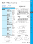
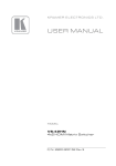
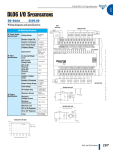
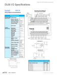
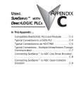
USING
SureStep™ WITH
AUTOMATIONDIRECT
PLCS
APPENDIX
B
In This Appendix...
Compatible DirectLOGIC PLCs and Modules . . . . . . . . . . . .B–2
Typical Connections to a DL05 PLC . . . . . . . . . . . . . . . . . . .B–4
Typical Connections to an H0-CTRIO . . . . . . . . . . . . . . . . .B–5
Typical Connections – Multiple Drives/Motors . . . . . . . . . .B–6
Typical DirectLOGIC PLC
Serial Connections to an Advanced SureStep Drive . . . . .B–7
Typical CLICK & P3000 PLC
Serial Connections to an Advanced SureStep Drive . . . . .B–8
Appendix B: Using SureStep™ with AutomationDirect PLCs
Compatible DirectLOGIC PLCs and Modules
The following tables show which high-speed pulse-output DirectLOGIC PLCs and
modules can be used with the SureStep Microstepping Motor Drives.
DirectLOGIC PLCs/Modules for Use with SureStep Drive (1)
DL05 PLCs
D0-05AD
D0-05DD
D0-05DD-D
DL05 CPU, 8 AC in / 6 DC out, 110/220 VAC power supply. Inputs: 8 AC inputs, 90-120
VAC, 2 isolated commons. Outputs: 6 DC outputs, 6-27 VDC current sinking, 1.0 A/pt max,
1 common. Two outputs are configurable for independent CW/CCW pulse train output or
step and direction pulse output up to 7kHz (0.5 A/pt.).
DL05 CPU, 8 DC in / 6 DC out, 110/220 VAC power supply. Inputs: 8 DC inputs, 12-24
VDC current sinking/sourcing, 2 isolated commons. Outputs: 6 DC outputs, 6-27 VDC
current sinking, 1.0 A/pt max, 1 common. Two outputs are configurable for independent
CW/CCW pulse train output or step and direction pulse output up to 7kHz (0.5 A/pt) (not
available when using high-speed inputs).
DL05 CPU, 8 DC in / 6 DC out, 12/24 VDC power supply. Inputs: 8 DC inputs, 12-24 VDC
current sinking/sourcing, 2 isolated commons. Outputs: 6 DC outputs, 6-27 VDC current
sinking, 1.0 A/pt max, 1 common. Two outputs are configurable for independent CW/CCW
pulse train output or step and direction pulse output up to 7kHz (0.5 A/pt.) (not available
when using high-speed inputs).
DL06 PLCs
DL06 CPU, 20 DC in / 16 DC out, 110/220 VAC power supply, with 0.3A 24 VDC auxiliary
device power supply. Inputs: 20 DC inputs, 12-24 VDC current sinking/sourcing, 5 isolated
commons (4 inputs per common). Outputs: 16 DC outputs, 12-24 VDC current sinking,
D0-06DD1 1.0A/pt max, 4 commons non-isolated (4 points per common). Two outputs are configurable
for independent CW/CCW pulse train output or step and direction pulse output up to 10 kHz
(0.5 A/pt) (not available when using high-speed inputs).
DL06 CPU, 20 DC in / 16 DC out, 110/220 VAC power supply, with 0.3A 24 VDC auxiliary
device power supply. Inputs: 20 DC inputs, 12-24 VDC current sinking/sourcing, 5 isolated
commons (4 inputs per common). Outputs: 16 DC outputs, 12-24 VDC current sourcing
D0-06DD2 1.0A/pt max, 4 commons non-isolated (4 points per common). Two outputs are configurable
for independent CW/CCW pulse train output or step and direction pulse output up to 10 kHz
(0.5 A/pt) (not available when using high-speed inputs).
DL06 CPU, 20 DC in / 16 DC out, 12/24 VDC power supply. Inputs: 20 DC inputs, 12-24
VDC current sinking/sourcing, 5 isolated commons (4 inputs per common). Outputs: 16 DC
D0-06DD1-D outputs, 12-24 VDC current sinking, 1.0 A/pt max, 4 commons non-isolated (4 pts/common).
Two outputs are configurable for independent CW/CCW pulse train output or step and
direction pulse output up to 10 kHz (0.5 A/pt) (not available when using high-speed inputs).
DL06 CPU, 20 DC in / 16 DC out, 12/24 VDC power supply. Inputs: 20 DC inputs, 12-24
VDC current sinking/sourcing, 5 isolated commons (4 inputs per common). Outputs: 16 DC
D0-06DD2-D outputs, 12-24VDC current sourcing, 1.0A/pt max, 4 commons non-isolated (4 pts/common).
Two outputs are configurable for independent CW/CCW pulse train output or step and
direction pulse output up to 10 kHz (0.5 A/pt) (not available when using high-speed inputs).
DL05/DL06 High Speed Counter I/O Module
H0-CTRIO
DL05/06 High Speed Counter I/O Interface Module, 4 DC sink/source inputs 9-30 VDC, 2
isolated sink/source DC outputs, 5-30 VDC, 1A per point. Inputs supported: 1 quadrature
encoder counters up to 100 kHz, or 2 single channel counters up to 100 kHz, and 2 high
speed discrete inputs for Reset, Inhibit, or Capture. Outputs supported: 2 independently
configurable high speed discrete outputs or 1 channel pulse output control, 20Hz-25kHz per
channel, pulse and direction or CW/CCW pulses.
Table continued next page.
B–2
SureStep™ Stepping Systems User Manual
Fourth Edition
12/2012
Appendix B: Using SureStep™ with AutomationDirect PLCs
DirectLOGIC PLCs/Modules for Use with SureStep Drive (1) (continued)
DL105 PLCs
F1-130AD
DL130 CPU, 10 AC in / 8 DC out, 110/220 VAC power supply. Inputs: 10 AC inputs, 80-132
VAC, 3 isolated commons. Outputs: 8 DC outputs, 5-30 VDC current sinking, 0.5A/pt max,
3 internally connected commons. Two outputs are configurable for independent CW/CCW
pulse train output or step and direction pulse output up to 7kHz (@ 0.25 A/pt max).
F1-130DD
DL130 CPU, 10 DC in / 8 DC out, 110/220 VAC power supply. Inputs: 10 DC inputs, 12-24
VDC current sinking/sourcing, 3 isolated commons. Outputs: 8 DC outputs, 5-30 VDC
current sinking, 0.5 A/pt max, 3 internally connected commons. Two outputs are
configurable for independent CW/CCW pulse train output or step and direction pulse output
up to 7kHz (@ 0.25 A/pt max) (not available when using high-speed inputs).
DL130 CPU, 10 DC in / 8 DC out, 12/24 VDC power supply. Inputs: 10 DC inputs, 12-24
VDC current sinking/sourcing, 3 isolated commons. Outputs: 8 DC outputs, 5-30 VDC
F1-130DD-D current sinking, 0.5 A/pt max, 3 internally connected commons. Two outputs are
configurable for independent CW/CCW pulse train output or step and direction pulse output
up to 7kHz (@ 0.25 A/pt max) (not available when using high-speed inputs).
DL205 High Speed Counter I/O Modules
DL205 High Speed Counter I/O Interface Module, 8 DC sink/source inputs 9-30 VDC, 4
isolated sink/source DC outputs, 5-30 VDC, 1A per point. Inputs supported: 2 quadrature
encoder
counters up to 100 kHz, or 4 single channel counters up to 100 kHz, and 4 high
H2-CTRIO(2) speed discrete inputs for Reset, Inhibit, or Capture. Outputs supported: 4 independently
configurable high speed discrete outputs or 2 channels pulse output control, 20 Hz - 25 kHz
per channel, pulse and direction or CW/CCW pulses.
D2-CTRINT
Counter Interface Module, 4 isolated DC inputs, 1 pulse train output (CW) or 2 pulse train
outputs (CW/CCW) with DC input restrictions, accepts two up-counters when used with D2240 or D2-250(-1) (one only with D2-230), or one up/down counter. (not available when
using high-speed inputs).
Terminator I/O High Speed Counter I/O Module
T1HCTRIO(2)
Terminator I/O High Speed Counter I/O Interface Module, 8 DC sink/source inputs 9-30
VDC, 4 isolated sink/source DC outputs, 5-30 VDC, 1A per point. Inputs supported: 2
quadrature encoder counters up to 100 kHz, or 4 single channel counters up to 100 kHz,
and 4 high speed discrete inputs for Reset, Inhibit, or Capture. Outputs supported: 4
independently configurable high speed discrete outputs or 2 channels pulse output control,
20 Hz - 25 kHz per channel, pulse and direction or CW/CCW pulses. (Use with T1K-16B or
T1K-16B-1 terminal base.)
DL405 High Speed Counter I/O Module
H4-CTRIO
DL405 High Speed Counter I/O Interface Module, 8 DC sink/source inputs 9-30 VDC, 4
isolated sink/source DC outputs, 5-30 VDC, 1A per point. Inputs supported: 2 quadrature
encoder counters up to 100 kHz, or 4 single channel counters up to 100 kHz, and 4 high
speed discrete inputs for Reset, Inhibit, or Capture. Outputs supported: 4 independently
configurable high speed discrete outputs or 2 channels pulse output control, 20 Hz - 25 kHz
per channel, pulse and direction or CW/CCW pulses.
(1) Any DirectLOGIC PLC capable of RS-232 ASCII communication can write serial commands
to the SureStep Advanced Microstepping Drives (STP-DRV-4850 & -80100). These PLCs
include DL 05, 06, 250-1, 260, 350, and 450. However, we strongly recommend using DL06
or DL260 PLCs for serial commands due to their more advanced ASCII instruction set which
includes PRINTV and VPRINT commands.
(2) The H2-CTRIO and T1H-CTRIO High Speed Counter I/O Interface Modules can also be used
to control the SureStep Stepping System in PC-Based Control systems with Think & Do/Studio,
or with our embedded WinPLC/EBC module plugged into the CPU slot of the DL205 base.
Fourth Edition
12/2012
SureStep™ Stepping Systems User Manual
B–3
Appendix B: Using SureStep™ with AutomationDirect PLCs
Typical Connections to a DL05 PLC
The following wiring diagram shows typical connections between the SureStep
Stepping System components and a DirectLOGIC DL05 PLC. Refer to the DL05
Micro PLC User Manual, p/n D0-USER-M, High-Speed Input and Pulse Output
Features chapter, for detailed programming instructions when using the PLC for
the Mode 30: Pulse Output function.
DL05 PLC programmed for
Mode 30: Pulse Output
D0-05DD PLC
L1 L2
LG
X0
X3
X2
C1
X4
X6
X5
C2
Y1
X7
Y0
Y2
Y3
Y5
Y4
+V
24 VDC
Power Supply
GND
+
AC Power
Step Motor
Power Supply
–
5 VDC xx VDC
L1
GND
120/240
VAC
L2
AC Power
GND
AC Power
120/240
VAC
STP-PWR-xxxx
L2
L1
PSP24-024S
G
X1
24 VDC
AC(L) AC(N) C0
–
+
Y1
–
0 VDC
+5 VDC
+
Step Motor Drive
STP-DRV-xxxx
EN–
EN+
VDC+
DIR–
VDC–
DIR+
A+
STEP–
A–
STEP+
N/C
N/C
Y0
B+
B–
Cable Color Code
Term Wire Pin #
A+
1
Red
A– White
2
B+ Green 3
B– Black
4
B–4
4
3
2
1
Front View
Extension Cable
with Connector
STP-EXT(H)-020
Step Motor
STP-MTR(H)-xxxxx
Connector
12" Motor Pigtail
with Connector
SureStep™ Stepping Systems User Manual
Fourth Edition
12/2012
Appendix B: Using SureStep™ with AutomationDirect PLCs
Typical Connections to an H0-CTRIO
The following wiring diagram shows typical connections between the SureStep
Stepping System components and a DirectLOGIC H0-CTRIO High Speed Counter
I/O Interface Module installed in either a DL05 or DL06 PLC option slot. Refer to
the CTRIO High-Speed Counter Module User Manual, p/n Hx-CTRIO-M, for
detailed programming instructions when using the H0-CTRIO module.
G
LG
0V
Y0
Y2
C1
Y5
Y7 Y10 Y12
C3 Y15 Y17
AC(L) AC(N) 24V C0
Y1
Y3
Y4
Y6
C2
Y11 Y13 Y14 Y16 N.C.
OUTPUT: 6-240V
Y
X
0
1
2
50 - 60Hz
3
INPUT: 12 - 24V
4
5
2.0A, 6 - 27V
6
7
10
2.0A
11
12
PWR: 100-240V
13
14
15
16
PWR
RUN
CPU
TX1
RX1
TX2
RX2
50-60Hz 40VA
17
20
D0-06DR
21 22
23
3 - 15mA
ERR
OK
Y0
A
LOGIC
C0
06
CTR/TMR IN
9–30V 5–12mA
DC/Pulse Out
5–36V 1A
IN
K oyo
X1
X0
X3
X2
X4
C1
Y1
B
X6
X5
X7
C2 X11 X13 X14 X16 C4 X21 X23 N.C.
X10 X12 C3
X15 X17 X20 X22 N.C.
TERM
PORT1
PORT2
RUN STOP
A
B
C
D
Step Motor
Power Supply
M
YC
5 VDC xx VDC
GND
L2
L1
Y0
Y1
AC Power
120/240
VAC
STP-PWR-xxxx
OUT
H0–CTRIO
–
+
Y1
–
0 VDC
+5 VDC
+
Step Motor Drive
STP-DRV-xxxx
EN–
EN+
N/C
N/C
DIR–
VDC+
DIR+
VDC–
A+
STEP–
A–
STEP+
Y0
B+
B–
Cable Color Code
Term Wire Pin #
A+
1
Red
A– White
2
B+ Green 3
B– Black
4
Fourth Edition
12/2012
4
3
2
1
Front View
Extension Cable
with Connector
STP-EXT(H)-020
Step Motor
STP-MTR(H)-xxxxx
Connector
12" Motor Pigtail
with Connector
SureStep™ Stepping Systems User Manual
B–5
Appendix B: Using SureStep™ with AutomationDirect PLCs
Typical Connections – Multiple Drives/Motors
The following wiring diagram shows typical connections between the SureStep
Stepping System components and a DirectLOGIC H2-CTRIO High Speed Counter
I/O Interface Module installed in a DL205 PLC. Refer to the CTRIO High-Speed
Counter Module User Manual, p/n Hx-CTRIO-M, for detailed programming
instructions when using the H2-CTRIO module.
CTR
+24VDC
IN
OUT PUTS
0
OK
1
ER
C1
2
C TR 2
3
H2--CTRI O
Step Motor
Power Supply
IN 9-30VDC 5-12mA
OUT 5-36VDC
1.0A max
per point
2A
STP-PWR-xxxx
2B
AC Power
120/240
VAC
GND
2C
L2
L1
2D
2M
1C
1D
1M
NC
C2
C0
Y2
Y0
C3
C1
Y3
Y1
–
5 VDC xx VDC
1A
1B
1A
2A
+
1B
–
0 VDC
2B
1C
+5 VDC
+
2C
Step Motor Drive
1D
STP-DRV-xxxx
EN–
EN+
VDC+
DIR–
VDC–
DIR+
A+
STEP–
A–
STEP+
N/C
N/C
2D
1M
2M
NC
C2
C0
Y2
B+
Y0
B–
C3
Step Motor
STP-MTR(H)-xxxxx
C1
Y3
Y1
Step Motor Drive
STP-DRV-xxxx
EN–
EN+
DIR–
VDC–
DIR+
A+
STEP–
4
3
A–
STEP+
2
1
B+
Front View
B–
Cable Color Code
Term Wire Pin #
A+
Red
1
A– White
2
B+ Green 3
B– Black
4
Extension Cable
with Connector
STP-EXT(H)-020
B–6
VDC+
N/C
N/C
Step Motor
STP-MTR(H)-xxxxx
12" Motor Pigtail
with Connector
SureStep™ Stepping Systems User Manual
Fourth Edition
12/2012
Appendix B: Using SureStep™ with AutomationDirect PLCs
Typical DirectLOGIC PLC
Serial Connections to an Advanced SureStep Drive
The following wiring diagrams show typical serial connections between a
SureStep Advanced Microstepping Drive and a DirectLOGIC PLC capable of RS232 ASCII communication. Refer to the particular PLC user manual for
instructions for writing ASCII serial commands.
Serial Connection Using Automation Direct Cables
ADVANCED STEPPER DRIVE
PLC - DL05
STP-DRV-4850
STP-DRV-80100
DL05 PLC
RS-232 Port 2
6P6C RJ12
Receptacle
�
RJ12
plug
STP-232RJ12-CBL-2
Red 5
Green 3
Blue 2
4 Red
3 Green
1 Blue
TXD 4
RXD 3
GND 1
RJ12
plug
�
ADVANCED STEPPER DRIVE
PLC
STP-DRV-4850
STP-DRV-80100
DL06
DL250-1
DL260
Port 2
15 pin HD
HD15
plug
3 RX
2 TX
7 GND
4 RTS
5 CTS
1
5
�
5 RX
3 TX
2 GND
�
6
Modular
6P4C RJ12
Receptacle
RJ12
plug
STP-232HD15-CBL-2
Yellow 3
Blue 5
Black 2
3
2
7
4
5
Modular
6P4C RJ12
Receptacle
�
3 TX
5 RX
2 GND
�
15
Serial Connection Using Custom Cables
Use Belden 9841 or equivalent cable, and wire according to the Automation
Direct cable diagrams shown above (including RTS/CTS jumper for DL06,
DL250-1, and DL260).
Fourth Edition
12/2012
SureStep™ Stepping Systems User Manual
B–7
Appendix B: Using SureStep™ with AutomationDirect PLCs
Typical CLICK & P3000 PLC
Serial Connections to an Advanced SureStep Drive
The following wiring diagrams show typical serial connections between a
SureStep Advanced Microstepping Drive and a CLICK PLC or a P3-550 PLC
capable of RS-232 ASCII communication. Refer to the particular PLC user manual
for instructions for writing ASCII serial commands.
Serial Connection Using Automation Direct Cables
ADVANCED
STEPPER DRIVE
PLC
STP-DRV-4850
STP-DRV-80100
CLICK PLC
P3-550 PLC
Port 2 (CLICK)
RS232 Port (P3-550)
RJ12 Receptacle �
TXD 4
RXD 3
GND 1
RJ12
plug
STP-232RJ12-CBL-2
4 Red
3 Green
1 Blue
Red 5
Green 3
Blue 2
�
RJ12
plug
Modular
6P4C RJ12
Receptacle
�
5 RX
3 TX
2 GND
�
Serial Connection Using Custom Cables
Use Belden 9841 or equivalent cable, and wire according to the Automation
Direct STP-232RJ12-CBL-2 diagram shown above.
B–8
SureStep™ Stepping Systems User Manual
Fourth Edition
12/2012