1
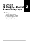
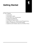
9–10
Maintenance and Troubleshooting
CPU Indicators
Maintenance
and Troubleshooting
The DL205 CPUs have indicators on the front to help you diagnose problems with
the system. The table below gives a quick reference of potential problems
associated with each status indicator. Following the table will be a detailed analysis
of each of these indicator problems.
Indicator Status
Potential Problems
PWR (off)
1. System voltage incorrect.
2. Power supply/CPU is faulty
3. Other component such an I/O module has power
supply shorted
4. Power budget exceeded for the base being used
RUN
(will not come on)
1. CPU programming error
2. Switch in TERM position
3. Switch in STOP position (DL250–1, DL260 only)
CPU (on)
1. Electrical noise interference
2. CPU defective
BATT (on)
1. CPU battery low
2. CPU battery missing, or disconnected
Status Indicators
DL260
DL250-1
Mode Switch
Maintenance
and Troubleshooting
Port 1
Port 2
Battery Slot
Status Indicators
PWR
BATT
PWR
BATT
RUN
CPU
RUN
CPU
DL240
DL230
CPU
CPU
Port 1
RUN
TERM
CH1
CH2
CH3
CH4
PORT 1
Port 2
PORT 1
PORT2
DL205 User Manual, 3rd Ed., Rev. A, 08/03
Mode Switch
9–11
Maintenance and Troubleshooting
PWR Indicator
There are four general reasons for the CPU power status LED (PWR) to be OFF:
1. Power to the base is incorrect or is not applied.
2. Base power supply is faulty.
3. Other component(s) have the power supply shut down.
4. Power budget for the base has been exceeded.
If the voltage to the power supply is not correct, the CPU and/or base may not
operate properly or may not operate at all. Use the following guidelines to correct the
problem.
WARNING: To minimize the risk of electrical shock, always disconnect the system
power before inspecting the physical wiring.
Faulty CPU
Maintenance
and Troubleshooting
1. First, disconnect the system power and check all incoming wiring for loose
connections.
2. If you are using a separate termination panel, check those connections to
make sure the wiring is connected to the proper location.
3. If the connections are acceptable, reconnect the system power and
measure the voltage at the base terminal strip to insure it is within
specification. If the voltage is not correct shut down the system and correct
the problem.
4. If all wiring is connected correctly and the incoming power is within the
specifications required, the base power supply should be returned for
repair.
There is not a good check to test for a faulty CPU other than substituting a known
good one to see if this corrects the problem. If you have experienced major power
surges, it is possible the CPU and power supply have been damaged. If you suspect
this is the cause of the power supply damage, a line conditioner which removes
damaging voltage spikes should be used in the future.
Maintenance
and Troubleshooting
Incorrect Base
Power
DL205 User Manual, 3rd Ed., Rev. A, 08/03
9–12
Maintenance and Troubleshooting
Device or Module
It is possible a faulty module or external device using the system 5V can shut down
causing the Power the power supply. This 5V can be coming from the base or from the CPU
communication ports.
Supply to
Shutdown
To test for a device causing this problem:
1. Turn off power to the CPU.
2. Disconnect all external devices (i.e., communication cables) from the CPU.
3. Reapply power to the system.
Maintenance
and Troubleshooting
If the power supply operates normally you may have either a shorted device or a
shorted cable. If the power supply does not operate normally then test for a module
causing the problem by following the steps below:
If the PWR LED operates normally the problem could be in one of the modules. To
isolate which module is causing the problem, disconnect the system power and
remove one module at a time until the PWR LED operates normally.
Follow the procedure below:
S Turn off power to the base.
S Remove a module from the base.
S Reapply power to the base.
Bent base connector pins on the module can cause this problem. Check to see the
connector is not the problem.
Maintenance
and Troubleshooting
Power Budget
Exceeded
If the machine had been operating correctly for a considerable amount of time prior
to the indicator going off, the power budget is not likely to be the problem. Power
budgeting problems usually occur during system start-up when the PLC is under
operation and the inputs/outputs are requiring more current than the base power
supply can provide.
WARNING: The PLC may reset if the power budget is exceeded. If there is any doubt
about the system power budget please check it at this time. Exceeding the power
budget can cause unpredictable results which can cause damage and injury. Verify
the modules in the base operate within the power budget for the chosen base. You
can find these tables in Chapter 4, Bases and I/O Configuration.
DL205 User Manual, 3rd Ed., Rev. A, 08/03
9–13
Maintenance and Troubleshooting
RUN Indicator
CPU Indicator
If the CPU indicator is on, a fatal error has occurred in the CPU. Generally, this is not
a programming problem but an actual hardware failure. You can power cycle the
system to clear the error. If the error clears, you should monitor the system and
determine what caused the problem. You will find this problem is sometimes caused
by high frequency electrical noise introduced into the CPU from an outside source.
Check your system grounding and install electrical noise filters if the grounding is
suspected. If power cycling the system does not reset the error, or if the problem
returns, you should replace the CPU.
Maintenance
and Troubleshooting
If the CPU will not enter the Run mode (the RUN indicator is off), the problem is
usually in the application program, unless the CPU has a fatal error. If a fatal error
has occurred, the CPU LED should be on. (You can use a programming device to
determine the cause of the error.)
If you are using a DL240, DL250–1 or DL260 and you are trying to change the modes
with a programming device, make sure the mode switch is in the TERM position.
Both of the programming devices, Handheld Programmer and DirectSOFT32, will
return a error message describing the problem. Depending on the error, there may
also be an AUX function you can use to help diagnose the problem. The most
common programming error is “Missing END Statement”. All application programs
require an END statement for proper termination. A complete list of error codes can
be found in Appendix B.
BATT Indicator
Communications Problems
If you cannot establish communications with the CPU, check these items.
S The cable is disconnected.
S The cable has a broken wire or has been wired incorrectly.
S The cable is improperly terminated or grounded.
S The device connected is not operating at the correct baud rate (9600
baud for the top port. Use AUX 56 to select the baud rate for the bottom
port on a DL240, DL250–1 and DL260).
S The device connected to the port is sending data incorrectly.
S A grounding difference exists between the two devices.
S Electrical noise is causing intermittent errors.
S The CPU has a bad communication port and the CPU should be
replaced.
If an error occurs the indicator will come on and stay on until a successful
communication has been completed.
Maintenance
and Troubleshooting
If the BATT indicator is on, the CPU battery is either disconnected or needs
replacing. The battery voltage is continuously monitored while the system voltage is
being supplied.
DL205 User Manual, 3rd Ed., Rev. A, 08/03