1
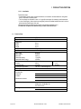
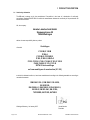
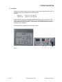
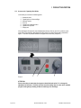
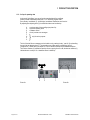
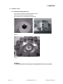
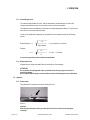
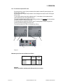
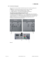
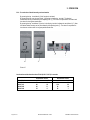
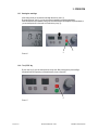
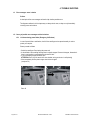
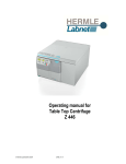
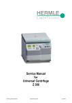
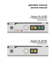
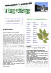
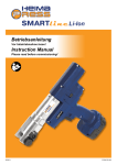
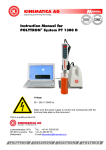
Instruction Manual
for
Compact Centrifuge
Z 206 A
Page 1 of 24
INSTRUCTION MANUAL Z 206 A
© HERMLE Labortechnik GmbH
CONTENTS
1 PRODUCT DESCRIPTION
1.1 Usage in accordance with safety standards
1.1.1 General Information
1.1.1.1 Hazards and precautions
1.1.1.2 Brief description
1.1.1.3 Safety Standards
1.1.1.4 Extent of supply
1.1.1.5 Warranty
1.2 Installation
1.2.1 Installation of the centrifuge
1.2.1.1 Unpacking the centrifuge
1.2.1.2 Space requirements
1.2.1.3 Installation
1.3 Technical Data
1.4 Conformity Declaration
1.5 Basic Setup and the “operating data” mode
1.5.1 Access to the “basic adjustments” mode
1.5.2 Call up of the “operating data” mode
2 OPERATION
2.1 Installation of rotors
2.1.1 Mounting and loading angle rotors
2.1.2 Mounting and loading swing out rotors
2.1.3 Overloading of rotors
2.1.4 Removing the rotors
2.2 Operation
2.2.1 Power switch
2.2.2 Lid release
2.2.3 Lid lock
2.2.4 Pre-selection of speed/RCF-value
2.2.5 Pre-selection of running time
2.2.6 Pre-selection of brake intensity and acceleration
2.2.7 Starting the centrifuge
2.2.8 “Stop“ key
2.3 Safety features
2.3.1 Imbalance detection
3 MAINTENANCE
3.1 Service and Maintenance
3.1.1 Maintenance and cleaning
3.1.2 Glass breakage
3.1.3 Disinfection of Alu-rotors
3.1.4 Disinfection of PP-rotors
4 TROUBLE SHOOTING
4.1 Error messages: Cause / Solution
4.2 Survey of possible error messages and their solutions
4.2.1 Lid release during power failure
4.2.2 Discription of the error message system
4.2.3 Error messages
Technical modification rights reserved
Page 2 of 24
INSTRUCTION MANUAL Z 206 A
© HERMLE Labortechnik GmbH
© HERMLE Labortechnik GmbH 2004/01
1 PRODUCT DESCRIPTION
1.1 Usage in accordance with safety standards
1.1.1 General information
This unit is a medicine product according to the IVD guide line 98/79/EG.
1.1.1.1 Hazards and precautions
Before setting the centrifuge into operation, please read this instruction manual carefully!
For your personal safety, please review the following precautions:
• The HERMLE Z 206 A is not explosion-proof and must therefore not be operated in explosionendangered areas or locations. During centrifugation, it is prohibited to stay within the safety zone of
30 cm around the centrifuge or deposit hazardous substances within this area.
• Centrifugation of flammable, explosive and radioactive substances, which chemically
react with high energy, is strictly prohibited!
• Never spin toxic or pathogenic material without adequate safety precautions, i.e. centrifugation of
buckets / tubes without or with defective hermetic sealings is strictly prohibited.
The user is obligated to perform appropriate disinfection procedures in the case that dangerous
substances have contaminated the centrifuge and / or the accessories. When centrifuging infectious
substances, always pay attention to the General Laboratory Precautions. If necessary, contact your
safety officer.
• It is prohibited to run the centrifuge with rotors that are not listed for this unit.
• Under no circumstances open the lid of the centrifuge while the rotor is still running or rotating with a
speed of > 2 m/s.
Following rules must strictly be adhered to:
• Do not operate the centrifuge in the case that it is not installed correctly.
• Do not operate the centrifuge when dismounted (e.g. without housing).
• Do not run the centrifuge when mechanical or electrical components have been tampered with
by unauthorized personnel.
• Do not use accessories such as rotors and buckets, which are not exclusively approved by
HERMLE Labortechnik GmbH, except commercially available centrifuge tubes made of glass
or plastic.
• Do not spin extremely corrosive substances, as they may cause material damages and impair
mechanical resistance.
• Do not operate the centrifuge with rotors or buckets, which show any signs of corrosion or mechanical
damage.
Page 3 of 24
INSTRUCTION MANUAL Z 206 A
© HERMLE Labortechnik GmbH
1 PRODUCT DESCRIPTION
The manufacturer is responsible for safety and reliability of the centrifuge when:
• The unit is operated in accordance with this instruction manual.
• Modifications, repairs or other adjustments are performed by HERMLE-authorized personnel and the
electrical installation of the related location corresponds to the IEC-regulations.
1.1.1.2 Brief description
Model Z 206 A is a compact small centrifuge capable of running swing out and angle rotors. All relevant
run parameters can easily be set with the display keys and be pre-selected with the main adjustment
knob. All pre-selected and actual values are permanently displayed on large LCD display.
The lid is latched and released with an electronic lid lock.
The centrifuge has a powerful, maintenance-free motor with a low noise level.
1.1.1.3 Safety standards
The centrifuge corresponds with the General Requirements for Medical Units Regulations (MedGV)
(group 3).
Following standards have been considered for the production of our centrifuges:
• Accident Prevention Regulation for electrical units and installations UVV VBG 4
• Accident Prevention Regulation for centrifuges as per BGR 500; Chapter 2.11; Part 3
• DIN 58970 part 1, 2 and 4 for centrifuges and tubes
• Electrical Interference Suppression according to interference degree B as per VDE 0871
• Electrical Safety as per IEC 1010-1 and IEC 1010-2-D
• European Standard PR EN 61 010-1 and PR EN 61 010-2-2
Page 4 of 24
INSTRUCTION MANUAL Z 206 A
© HERMLE Labortechnik GmbH
1 PRODUCT DESCRIPTION
1.1.1.4 Included Accessories
Following parts are supplied as accessories with each centrifuge:
• 1 Instruction manual
1.1.1.5 Warranty
The centrifuge has been subjected to thorough testing and quality control procedures.
In the unlikely case of any manufacturing faults occurring, the centrifuge and rotors are covered by
warranty for a period of two year from date of delivery.
This warranty becomes invalid in case of mishandling, negligence, and further in case of
usage of inappropriate spare parts and / or accessories, as well as any unauthorized modification
of the unit.
Technical modification rights are reserved by the manufacturer in respect to technical
improvement.
1.2 Installation
1.2.1 Installation of the centrifuge
1.2.1.1 Unpacking the centrifuge
Model Z 206 A is supplied in a carton.
Remove the strap retainer, open the carton and remove the centrifuge. The instruction
manual should always be kept with the centrifuge.
1.2.1.2 Space requirements
The centrifuge should be installed on an even and solid surface, if possible on a laboratory
cabinet / table or some other solid vibration free surface.
In order to enable a safe and smooth operation, level the centrifuge with a levelling device.
The centrifuge must be placed in a way, that there is a minimum space of 30 cm on each side of the unit
in order to ensure the necessary heat dissipation.
Do not place the centrifuge next to a window or a heater, where it could be disposed to excessive heat,
as the performance of the unit is based on an ambient temperature of 23°C.
Safety regulations require that the safety area of 30 cm around the unit is marked in order to indicate
that neither hazardous substances nor persons should be within this area during centrifugation.
Page 5 of 24
INSTRUCTION MANUAL Z 206 A
© HERMLE Labortechnik GmbH
1 PRODUCT DESCRIPTION
1.2.1.3 Installation
Follow these steps:
• Check whether power supply corresponds with the one named on the manufacturer's rating label
which is mounted on the rear panel.
• The line voltage circuit breaker is max. 10 A (type K) slow release for commonly used instruments.
• In case of emergency, there must be an emergency switch off installed outside the room in order to
disconnect the power supply of the unit.
(• Remove the transport spacer blocks from the motor shaft (see chapter 2.2.2).)
The outlet for the power cord must be easy to reach and to disconnect!
1.3 Technical Data
Manufacturer
Type / Model
Dimensions
Width
Depth
Height
Weight
Noise level (max.)
Max. speed
Max. volume
Max. RCF
Admissible density
Admissible kinetic energy
Electrical connection AC
Current
Connected load
Interference suppression
Test obligations
To be filled in by purchaser:
Inventory-No.:
Check-No.:
Location:
Maintenance contract:
HERMLE Labortechnik GmbH
Z 206 A
Your service department
Labnet International
PO Box 841, Woodbridge, NJ
Ph: 732-417-0700
28 cm
37 cm
26 cm
15 kg
60 +2.0 dB (A)
6000 rpm
6 x 50 ml
4185 x g
1.2 kg/dm3
1694 Nm
230 V / 50 Hz 1 ph
0.55 A
100 Watt
VDE 0871, Funkentstörgrad B
120 V / 60 Hz 1 ph
1.1 A
100 Watt
Your agent
Page 6 of 24
INSTRUCTION MANUAL Z 206 A
© HERMLE Labortechnik GmbH
1 PRODUCT DESCRIPTION
1.4 Conformity declaration
The CE-mark is always set by the manufacturer. Precondition is the issue of a declaration of conformity
according to Standard DIN EN 45014 in which the manufacturer declares the conformity of the product with all
relevant EU directions.
We, the company
Hermle Labortechnik GmbH
Siemensstrasse 25
78564 Wehingen
declare in mere responsibility that our product
Centrifuges
of models
Z 100 M; Z 160 M
Z 206 A
Z 233 M-2; Z 233 MK-2
Z 300; Z 300 K; SIEVA-2
Z 323; Z 323 K; Z 366; Z 36 HK; Z 383; Z 383 K
Z 400; Z 400 K; Z 513; Z 513 K
SETA Oil test centrifuge
as from month/year of construction (01 / 05)
to which this declaration refers to, have been manufactured according to the following standards or according to
normative documents.
DIN EN 61 010-1; DIN EN 61 010-2-020;
EN 50501/B;
EN 61000-6-1; EN 61000-3-2; EN 61000-3-3;
EN 292-2; EN 292-2/A1; EN 61326;
73/23/EWG; 98/37/EG; 98/79/EG
Wehingen/Germany, 1st January 2007
Page 7 of 24
Harald Hermle
President
INSTRUCTION MANUAL Z 206 A
© HERMLE Labortechnik GmbH
1 PRODUCT DESCRIPTION
1.5 Initial Setup
Before the first operation and after each rotor change, you have to select the appropriate rotor code. You
can find each rotor type in the printed order number on the rotor.
Example:
Angle rotor
220.96 V01 ≙ Rotor type “96“
Swing out rotor
220.68 V04 ≙ Rotor type “68“
Switch on the unit and open the lid. Now press simultaneously the keys “lid “ (1) and “stop” (2). In the
display “rpm/rcf” then appears the selected rotor type, ex. “96”. With the adjustment knob (7) you can
select the desired rotor code. (See photo 1) To set the data in the unit please wait until the indication in
the display “rpm/rcf” disappears.
Now all important rotor parameters for the centrifuge are stored.
1
Photo 1
Page 8 of 24
INSTRUCTION MANUAL Z 206 A
2
7
© HERMLE Labortechnik GmbH
1 PRODUCT DESCRIPTION
1.5.1 Access to the “Operating Data“ Mode
In this mode you can check the following points:
1.
2.
3.
4.
5.
6.
7.
Number of starts
Operating hours of the centrifuge
Software-version
Error list
Operation of imbalance sensor
Operation of keyboard
Display test
If the centrifuge is still turned off, press simultaneously the keys “time“ (4) and “lid“ (1) and turn on the
main switch of the centrifuge. Now release both keys again. As a result a display test is executed for
approx. 5 seconds. All possible indications will appear at the same time (see photo 2 ).
Photo 2
4
1
7
ATTENTION:
Please notice that you must enter the program as described under point 1.5.1 to change the
adjustments of the points 1.5.2. After you have stored the settings you can return to the standard
program mode again by switching off and the switching on the centrifuge.
Page 9 of 24
INSTRUCTION MANUAL Z 206 A
© HERMLE Labortechnik GmbH
1 PRODUCT DESCRIPTION
1.5.2 Call up of operating data
In the mode “Initial Setup“ you can call up the operating data of the centrifuge.
Please proceed as described under point 1.5.1 to enter this program mode.
Press the key “accel/decel“ (5). In the display “accel/decel“ flashes the word “service“.
By adjusting the adjusting knob (7) the information below can be called up:
A
H
S
E
F
U
P
C
= previous starts of the centrifuge (see photo 3a)
= previous operating hours
= software version
= list of previous error messages
only for service purpose
The list of the last 99 error messages can be looked over by pressing the key “rpm/rcf“ (6) and scrolling
through it by the adjusting knob (7). The respective error codes appear in the display “rpm/rcf“
(see photo 3b). Please look up in chapter 4.2.3 of this instuction manual for the detailed description.
The first two numbers (X) indicate the quantity of errors ongoing from 00 to 99, the last two numbers (Y)
indicate the error code (ex. 02 = imbalance sensor is defective).
X
6
5
Photo 3a
Page 10 of 24
Y
7
Photo 3b
INSTRUCTION MANUAL Z 206 A
© HERMLE Labortechnik GmbH
2 OPERATION
2.1 Installation of rotors
2.1.1 Mounting and loading angle rotors
Clean the drive shaft with a clean, grease-free piece of cloth.
Place the rotor onto the drive shaft. (see photo 4)
Be sure that the rotor is fully installed on the motor shaft.
Photo 4
Photo 5
ATTENTION:
For safety always ensure that rotor fixing screw is tightened before each run. (see photo 5)
Page 11 of 24
INSTRUCTION MANUAL Z 206 A
© HERMLE Labortechnik GmbH
2 OPERATION
Hold the rotor with one hand and secure the rotor to the shaft by turning the fixing screw (1)
clockwise. (see photo 6).
1
photo 6
ATTENTION:
For safety always ensure that rotor fixing screw is tightened before each run. (see photo 6)
It is allowed to operate a 12-place-rotor with 2 or 4 loaded tubes only.
But the loaded borings must be opposite each other.
Photo 7: incorrect
Page 12 of 24
Photo 8: correct
INSTRUCTION MANUAL Z 206 A
© HERMLE Labortechnik GmbH
2 OPERATION
2.1.2 Mounting and loading swing out rotors
Clean the drive shaft with a clean and grease-free cloth. Place the rotor to the motor shaft. Be sure that
the rotor is fully installed onto the motor shaft.
Hold the rotor with one hand and secure the rotor to the shaft by turning the rotor screw (1) clockwise.
The installation of the buckets and the adapters must be done appropriately photo 10.
In principle swing out rotors may not be taken in operation untill all buckets or racks are put into
the rotor.
The bolts at the rotor must be greased with silicone grease.
The sample tubes have to be filled evenly by eye and put into the drillings or tube racks. The weight
difference of the loaded buckets should not exceed approx. 1.0 g.
It is allowed to operate e.g. a 6-place-rotor with 2 loaded buckets only. But the loaded buckets must be
opposite to each other. Make sure that the unloaded buckets also be put inside the rotor (see photo 9
and 10).
ATTENTION:
Always fill all rotor positions with rotor buckets.
Photo 9: incorrect
Page 13 of 24
Photo 10: right
INSTRUCTION MANUAL Z 206 A
© HERMLE Labortechnik GmbH
2 OPERATION
2.1.3 Overloading of rotors
The maximum load permitted for a rotor, which is determined by the manufacturer, as well as the
maximum speed allowed for this rotor (see label on rotor), must not be exceeded.
The liquids the rotors are loaded with, should have an average homogeneous density of 1,2 g/ml or less
when the rotor is running at maximum speed.
In order to spin liquids with a higher density, the speed has to be reduced according to the following
formula:
Reduced speed nred =
1,2
higher density
x max. speed (nmax) of the rotor
Example:
1,2
nred =
x 4.000 = 3.360 rpm
1,7
In case of any questions, please contact the manufacturer.
2.1.4 Removing the rotor
Untighten the rotor fixing screw and lift the rotor vertically out of the centrifuge.
ATTENTION:
Do not operate the centrifuge with rotors or buckets which show any signs of corrosion or
mechanical damage.
Do not operate with extremely corrosive substances which could damage the rotor and buckets.
2.2 Operation
2.2.1 Power switch
The power switch is located on the bottom, left side of the unit.
Photo 11
Attention:
After turning on the power switch you must open the lid of the unit first, prior starting the
centrifuge.
Page 14 of 24
INSTRUCTION MANUAL Z 206 A
© HERMLE Labortechnik GmbH
2 OPERATION
2.2.2 Lid release
Once the centrifuge lid is closed the display shows “rpm/rcf“ and “close“ (8). At the same time the preselected rotor type is indicated, ex.. “nr 96” (11). During the run you can call up the rotor type at any time
by pressing the key “lid” (1). By pressing the key “lid“ (1) you can release the lid of centrifuge. As soon
as the electronic lid is completely released, it appears the word “open“ (9). Now you can open the lid of
the centrifuge. (see photo 12)
8
10
11
1
9
Photo 12
2.2.3 Lid lock
Attention: Before closing the lid please ensure that the rotor is tight.
As a sign that the centrifuge is ready for operation the display reads ‘rpm/rcf“ the word “close“ (8).
Simultaneously it appears in that display the word “rotor“ (10), as well as the code number of the rotor,
which is in the centrifuge ex. “nr 96“ (11).
Page 15 of 24
INSTRUCTION MANUAL Z 206 A
© HERMLE Labortechnik GmbH
2 OPERATION
2.2.4 Pre-selection of speed / RCF-value
By pressing the key “rpm/rcf“ (6) the pre-selection of the speed is activated. By pressing the key once
the word “rpm“ (12) flashes.
By pressing the key once again the pre-selection of the centrifugal forces may be chosen. Flashing the
word “rcf“ (13).
You can set the desired values with the adjusting knob (7). In the display (14) the regulated value is
shown permanently, before, during and after the run.
The speed is adjustable between 200 rpm and maximum revolution of the centrifuge resp. the maximum
permissible revolution of the pre-selected rotor.
It is the same with the pre-selection of the RCF-value. The setting range is between 20 xg and the
maximum permissible centrifugal force of the rotor.
The maximum speed of the Z 206 A is 6000 rpm resp. 4180 xg.
13
12
14
14
6
7
Photo 13
Maximum speed of the rotors available for the Z 206 A
Rotor-Number
220.96 V01
220.97 V01
220.95 V06
220.68 V04
Max.
Revolution
6000 rpm
6000 rpm
6000 rpm
3500 rpm
RCF
Value
4180 xg
3820 xg
2930 xg
1450 xg
Attention:
Please also check the maximum permissible speed of your test tubes.
Page 16 of 24
INSTRUCTION MANUAL Z 206 A
© HERMLE Labortechnik GmbH
2 OPERATION
2.2.5 Pre-selection of running time
The running time can be pre-selected in three different ranges from 10 seconds up to 99 hours 59
minutes.
1. Range from 10 seconds up to 59 minutes 50 seconds in steps of 10 seconds
2. Range from 1 hour up to 99 hours 59 minutes in steps of 1 minutes
3. Range continuous run “cont”, which can be interupted by the key “stop” (2).
The running time can be pre-selected with the lid opened or closed.
To activate the setting of the running time press the key “time“ (4).
In the display “time“ flashes the indication “m : s“ or “h : m“ (15), depending on the previous setting.
To set the desired value use the adjusting knob (7). After exceeding of 59 min 50 sec the indication (15)
changes automatically to “h : m“. After exceeding of 99 hours 59 min the word “cont” appears in the
display “time”. That continuous run can only be interupted by pressing the key “stop” (2).
The display shows always the remaining running time.
15
15
4
7
Photo 14
Page 17 of 24
2
INSTRUCTION MANUAL Z 206 A
© HERMLE Labortechnik GmbH
2 OPERATION
2.2.6 Pre-selection of brake intensity and acceleration
By pressing the key “accel/decel“ (5) this function is activated.
By pressing the key once the word “accel“ (16) flashes in the display “acc/dec“. The desired
acceleration can be pre-selected by the adjusting knob (7). The value 0 is equivalent to the lowest and
the value 9 to the highest acceleration.
By pressing the key “accel/decel“ (5) twice, in the display “acc/dec“ indicates the word “decel“ (17). Now
the desired brake intensity can be pre-selected by the adjusting knob (7). The value 9 is equivalent to
the shortest and the value 0 to longest possible brake time.
5
16
7
17
Photo 15
Acceleration and deceleration times Z 206 A(120 V / 230 V) in seconds
Acceleration values
Rotor-Number
220.96 V01
220.97 V01
220.95 V06
220.68 V04
Page 18 of 24
Level 0
70
80
60
35
Level 9
40
35
11
8
INSTRUCTION MANUAL Z 206 A
Deceleration values
Level 0
150
150
30
25
Level 9
35
35
10
7
© HERMLE Labortechnik GmbH
2 OPERATION
2.2.7 Starting the centrifuge
After closing the lid you can start the centrifuge with the key “start“ (3).
By pressing the key “start“ (3) you can start runs with manually pre-selected parameters.
When the respective pre-selected running time has ended then the centrifuge will stop automatically or
you can interupt the run in the mode “cont” with the key “stop” (2).
2
3
Photo 16
2.2.8 The „STOP“ key
By the “stop“ key (2) you can interrupt the run at any time. After pressing the key the centrifuge
decelerates with the respective pre-selected intensity down to stand still.
2
Photo 17
Page 19 of 24
INSTRUCTION MANUAL Z 206 A
© HERMLE Labortechnik GmbH
2 OPERATION
2.3 Safety features
2.3.1 Imbalance detection
In case of the rotor not being equally loaded, the drive will turn off during acceleration. The rotor
decelerates to stand still.
When in the display “time” the word “error” together with the number “01” (18) appear, the weight
difference of the samples is too huge. Weigh out the samples exactly.
Load the rotor as described in chapter 2.1.1.
When in the display “time” the word “error” together with the number “02“ (18) appear, there could be
following reasons:
• The imbalance switch is defective.
18
Photo 18
Page 20 of 24
INSTRUCTION MANUAL Z 206 A
© HERMLE Labortechnik GmbH
3 MAINTENANCE
3.1 Service and maintenance
3.1.1 Maintenance and cleaning
Maintenance:
Maintenance of the centrifuge is confined to keeping the rotor, the rotor chamber and the rotor
accessories clean as well as to regularly lubricating the rotor insert bolts of a swing out rotor (If
included).
Vaseline, available in nearly each store, is the most suitable lubricant. The Vaseline must be free of resin
and acids. Lubricants containing molycote and graphite are not allowed.
Please pay special attention to anodized aluminium parts. Breakage of rotors can be caused even by
slightest damages.
In case of rotors, buckets or tube racks getting in touch with corrosive substances the concerned spots
have to be cleaned carefully.
Examples of corrosive substances are:
•
•
•
•
•
•
•
Alkalis
Alkaline soap solutions
Alkaline amines
Concentrated acids
Solutions containing heavy metals
Water-free chlorinated solvents
Saline solutions, e.g. salt water
Cleaning:
Thorough cleaning not only has its purpose in hygiene but also in avoiding corrosion based on pollution.
In order to avoid damaging anodized parts such as rotors, reduction plates etc., only pH-neutral
Detergents with a pH-value of 6-8 may be used for cleaning.
Alkaline cleaning agents (pH-value > 8) must not be used.
After cleaning, please ensure all parts are dried thoroughly, either by hand or in a hot-air cabinet
(max. Temperature + 50°C).
It is necessary to coat anodized aluminium parts with anti-corrosion oil regularly in order to increase their
life-spans and reduce corrosion predisposition.
Due to humidity or not hermetically sealed samples, condensation may form. The condensation
has to be removed from the rotor chamber with a soft cloth regularly.
The maintenance procedure should be repeated every 10 to 15 runs, but at least once a week.
Page 21 of 24
INSTRUCTION MANUAL Z 206 A
© HERMLE Labortechnik GmbH
3 MAINTENANCE
3.1.2 Glass breakage
With high g-values, the rate of glass tube breakage increases. Glass splinters have to be removed
immediately from rotor, buckets, adapters and the rotor chamber itself. Fine glass splinters will scratch
and therefore damage the protective surface coating of a rotor.
If glass splinters remain in the rotor chamber, fine metal dust will build up due to air circulation. This
very fine, black metal dust will extremely pollute the rotor chamber, the rotor, the buckets and the
samples.
ATTENTION:
Please check the relevant specifications of the tubes centrifuged with the tube manufacturer.
3.1.3 Disinfection of aluminum-rotors
In case of infectious material spilling into the centrifuge, the rotor and rotor chamber have to be
disinfected right after the run. Rotors may be autoclaved at a maximum temperature of 121°C.
The rotor and rotor chamber should be cleaned with a universal, neutral disinfection agent, e.g. on
formalin base. A disinfection spray is most suitable in order to easily reach all difficult to access spots.
ATTENTION:
Before applying any other cleaning or decontamination method other than recommended by the
manufacturer, contact the manufacturer to ensure that it will not damage the unit or
the rotor.
3.1.4 Disinfection of PP-rotors
Autoclaving
The recommended time for autoclaving:
15 – 20 min at 121°C (1 bar)
ATTENTION: The sterilization time of 20 min. must not be exceeded. Sterilization again and again
will cause reduction of the mechanical resistance of the plastic material.
Before the autoclaving the PP-rotor and adapter must thoroughly be cleaned to avoid the burning in of
dirty residues.
You can disregard the consequences of some chemical residues to plastic materials at ambient
temperatures. But at the high temperatures of the autoclaving those residues may corrode and destroy
the plastic. The objects must be thoroughly washed up with distilled water after the cleaning but before
the autoclaving. Residues of any cleaning liquids may cause fissures, whitening and stains.
Gassterilization
Boxes, bottles and rotors may be gassterilized with Ethylenoxyd. According to the duration of the
application you may give long enough an airing to the items after the sterilization and before using them
again.
ATTENTION: Because the temperature may rise during the sterilization, rotors, boxes and bottles
must not be closed respectively must be totally unscrewed.
Chemical sterilization
Bottles, boxes and rotors may be treated with the usual liquid disinfectants.
Page 22 of 24
INSTRUCTION MANUAL Z 206 A
© HERMLE Labortechnik GmbH
4 TROUBLE SHOOTING
4.1 Error messages: cause / solution
Preface:
A description of the error messages are listed to help localize possible errors.
The diagnoses referred to in this chapter may not always be the case, as they are only theoretically
occurring errors and solutions.
4.2 Survey of possible error messages and their solutions
4.2.1 Lid release during power failure (Emergency Lid Release)
In case of power failure or malfunction, the lid of the centrifuge can be opened manually in order to
protect your samples.
Please proceed as follows:
• Switch the centrifuge off and unplug the power cord.
• At the left side of the centrifuge housing there is a plastic stopper. Remove this stopper, fastened to it
there is a string which is connected to the electronic lid lock.
• If you pull the string slightly the lid will open.
ATTENTION: Don’t put your hands in the rotor chamber as long as the rotor is still spinning!
• When completed, push the plastic stopper back in the unit again.
(see photo 19)
Photo 19
Page 23 of 24
INSTRUCTION MANUAL Z 206 A
© HERMLE Labortechnik GmbH
4 TROUBLE SHOOTING
4.2.2 Description of the error message system
The error message is shown in the "time" display through a two-digit number (19). At the same time the
word “error” (20) is indicated in the display (see photo 20).
20
19
Photo 20
4.2.3 Error messages
Errors that may be indicated in the LCD display:
Error No.:
01
02
14
30
33
34
55
60
70
Page 24 of 24
Description
Rotor Imbalance
Imbalance sensor is defective
Leap of speed is too big between measurements
Motor Error
Open lid while the motor is running
Lid contact defective
Overspeed
Undervoltage in the intermediate circuit
Blackout of the relay
INSTRUCTION MANUAL Z 206 A
© HERMLE Labortechnik GmbH