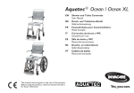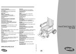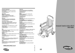
1
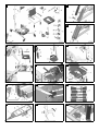
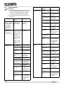
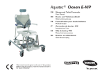
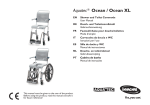
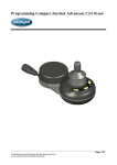
OCEAN E-VIP
DE
ES
Dusch- und Toilettenrollstuhl
Silla de ducha y WC
Gebrauchsanweisung
Manual de instrucciones
EN
SV
Commode
Dusch- och toalettstol
Operating Instructions
Bruksanvisning
FR
Chaise roulante pour douche/
toilettes
Mode d’emploi
NL
Douche- en toiletrolstoel
Gebruiksaanwijzing
IT
Carrozzina da doccia e da
toilette
Istruzioni per l’uso
FI
Suihku- ja wc-pyörätuoli
Käyttöohje
NO
Dusj- og toalettstol
Bruksanvisning
DA
Bruse- og toiletkørestol
Betjeningsvejledning
DE
ES
¡IMPORTANTE!
WICHTIG!
Bitte lesen Sie diese Gebrauchsanweisung aufmerksam durch, bevor Sie das Produkt benutzen. Beachten
Sie alle Hinweise, insbesondere die Sicherheitshinweise, und handeln Sie danach.
EN
Por favor lea este manual de instrucciones atentamente
antes de utilizar el producto. Tenga en cuenta todas las
indicaciones, especialmente las relativas a la seguridad, y sígalas.
SV
OBSERVERA!
IMPORTANT!
Before you use the product, please read these operating instructions carefully. Pay attention to all instructions, especially those regarding safety, and follow them
at all times.
FR
Läs igenom bruksanvisningen noggrant innan produkten används. Beakta och följ alla anvisningar, i synnerhet säkerhetsanvisningarna.
FI
TÄRKEÄÄ!
IMPORTANT !
Veuillez lire attentivement ce mode d’emploi avant d’utiliser le produit. Veuillez respecter toutes les consignes,
notamment les consignes de sécurité, et agir en conséquence.
NL
Lukekaa tämä käyttöohje huolellisesti, ennen kuin käytätte tuotetta. Noudattakaa kaikkia ohjeita, erityisesti
turvaohjeita, ja toimikaa niiden mukaisesti.
NO
VIKTIG!
BELANGRIJK!
Lees deze gebruiksaanwijzing aandachtig door, voordat
u het product gebruikt. Neem alle instructies in acht,
vooral de veiligheidsinstructies en volg deze op.
IT
Les bruksanvisningen nøye før du tar i bruk produktet.
Følg alle henvisningene, spesielt ang. sikkerhet.
DA
IMPORTANTE!
Si prega di leggere attentamente queste istruzioni per
l’uso prima di utilizzare il prodotto. Attenersi a tutte le indicazioni, in particolar modo a quelle relative alla sicurezza e procedere di conseguenza.
VIGTIGT!
Læs denne betjeningsvejledning opmærksomt igennem, før du anvender produktet. Læg mærke til alle
henvisninger, især sikkerhedshenvisningerne, og overhold dem.
1
2
3
4
5
6
7
8
9
10
11
12
13
14
15
16
Contents
1
1.1
1.2
1.3
1.4
1.5
1.6
General instructions . . . . . . . . . . . . . . . . 15
Introduction . . . . . . . . . . . . . . . . . . . . . . . . 15
Proper use . . . . . . . . . . . . . . . . . . . . . . . . 15
Warranty . . . . . . . . . . . . . . . . . . . . . . . . . . 15
Re-use/Reconditioning . . . . . . . . . . . . . . . 15
Disposal . . . . . . . . . . . . . . . . . . . . . . . . . . 15
CE marking . . . . . . . . . . . . . . . . . . . . . . . . 15
2
2.1
2.2
2.3
Safety instructions . . . . . . . . . . . . . . . . . 15
Warnings and symbols . . . . . . . . . . . . . . . 15
General instructions . . . . . . . . . . . . . . . . . 15
Instructions on the battery
and charger. . . . . . . . . . . . . . . . . . . . . . . . 16
3
3.1
3.2
Description . . . . . . . . . . . . . . . . . . . . . . . 16
Scope of delivery . . . . . . . . . . . . . . . . . . . 16
Technical data. . . . . . . . . . . . . . . . . . . . . . 16
4
Transport . . . . . . . . . . . . . . . . . . . . . . . . . 16
5
5.1
5.1.1
5.1.2
5.1.3
5.1.4
5.1.5
5.2
Setting up . . . . . . . . . . . . . . . . . . . . . . . . 16
Assembling the commode. . . . . . . . . . . . . 17
Mounting the seat frame . . . . . . . . . . . . . . 17
Fitting the footrests . . . . . . . . . . . . . . . . . . 17
Fitting the headrest . . . . . . . . . . . . . . . . . . 17
Attaching the chest belt. . . . . . . . . . . . . . . 17
Mounting the seat plate. . . . . . . . . . . . . . . 18
Recharging the battery . . . . . . . . . . . . . . . 18
6
6.1
6.2
6.3
6.4
6.5
6.6
6.7
6.7.1
6.7.2
6.7.3
6.8
6.9
6.10
6.11
6.12
Operation . . . . . . . . . . . . . . . . . . . . . . . . . 18
Adjusting the height of the footrests . . . . . 18
Adjusting the height of the armrests . . . . . 18
Adjusting the backrest cover. . . . . . . . . . . 19
Adjusting the position of the chest belt . . . 19
Adjusting the length of the chest belt . . . . 19
Adjusting the length of the heel loop. . . . . 19
Use . . . . . . . . . . . . . . . . . . . . . . . . . . . . . . 20
Folding the arm rests . . . . . . . . . . . . . . . . 20
Folding the footrests . . . . . . . . . . . . . . . . . 20
Controlling. . . . . . . . . . . . . . . . . . . . . . . . . 20
Locking the position locking device. . . . . . 21
Detaching and attaching the seat plate. . . 21
Removing and attaching the heel loop . . . 21
Removing the battery box . . . . . . . . . . . . . 21
Troubleshooting . . . . . . . . . . . . . . . . . . . . 22
14
7
7.1
7.2
7.3
7.4
7.5
Care and maintenance. . . . . . . . . . . . . .
Cleaning the seat frame
and main frame . . . . . . . . . . . . . . . . . . . .
Cleaning the charger and battery box . . .
Maintaining battery box performance. . . .
Changing the casters . . . . . . . . . . . . . . . .
Changing the drive mechanisms . . . . . . .
EN
23
23
24
24
24
24
1
1.1
General instructions
Introduction
These operating instructions contain information and
instructions regarding the safe and proper use of your
commode.
2
Safety instructions
2.1
The following warnings and symbols are used in these
operating instructions:
In the text of these operating instructions, we refer to
figures and individual items within the figures. These
references are shown in brackets. Example: (3, fig. 2)
refers to figure 2, item 3.
*
This notice indicates a potential hazard.
Important!
This symbol indicates additional instructions,
information or tips.
Proper use
The commode is to be used solely as an aid for showering or bathing, going to the toilet or for transfer indoors.
CAUTION!
Not following these instructions can result in injury or damage.
Keep all documents supplied in a safe place.
1.2
Warnings and symbols
2.2
General instructions
Lock the brakes in the parked position.
Any other use is prohibited.
Do not use the commode outdoors or as a climbing
aid.
Only use the commode indoors and on even,
flat surfaces.
The commode can be used as a commode for standard toilets or with an (optional) sanitary pan.
1.3
Warranty
Always use the chest belt when transporting
a person.
AQUATEC provides the product with a 2 year warranty. The rechargeable battery in the battery box is not
included in the warranty.
The warranty period begins at the delivery date as
shown on the AQUATEC delivery note.
1.4
Do not use the commode as a climbing aid.
Re-use/Reconditioning
The product is designed for repeated use. The maximum number of times you can re-use the product depends on its general state and condition.
If you detect any malfunction, please contact
your authorised dealer immediately.
On reconditioning, always follow the AQUATEC reconditioning and hygiene instructions. These are available
on request from AQUATEC.
Do not modify or reconstruct the device.
1.5
Never carry out work on the spindles or the
electric components. Please contact your authorised dealer immediately if a spindle is
damaged or faulty.
Disposal
The disposal and recycling of old devices
and packaging must be conducted in accordance with the applicable legal regulations.
1.6
Observe the information on the label. Do not
overload the commode.
CE marking
The product complies with EU directive 93/42/EEC for
medical equipment.
Transport or store the product in a dry room
at a temperature between 0 °C and 40 °C
and a humidity of 30 to 75 %.
The product meets the requirements of the
DIN EN 60601-1-2 norm (electromagnetic compatibility) and the DIN EN 12182 norm (technical aids for disabled persons).
*
EN
In the text, a picture illustrating the type of risk replaces the asterisk.
15
Never store the product directly next to heat
sources.
Never expose the product to direct sunlight.
2.3
Instructions on the battery and charger
Never throw the battery box into a fire. Do
not store it near naked flames.
Do not open the battery box. The warranty
expires if it is opened!
Use only the charger provided to recharge
the rechargeable battery in the battery box.
Recharge the battery in the battery box as
soon as possible after use.
To preserve the service life of the battery
when not in use for prolonged periods,
please observe the instructions in
section 7.3.
Only plug the charger into the mains when
the battery box is connected to the charger.
Except when charging the rechargeable battery, the battery box socket must always be
sealed with the cap.
3
3.1
Description
Scope of delivery
The AQUATEC E-VIP is supplied with the following
parts (fig. 1):
1
2
3
4
5
Head support
Operating instructions
Chest belt
Seat plate
Pins (4 x), safety clips (4 x), clips for footrests
(2 x), cable tie (1 x) packed in a bag
6 Footrests with heel loops (2 x)
7 Frame with hand control and control box with battery box and drive mechanisms
8 Seat frame with backrest cover and armrests
9 Charger
10 Drive for tilt adjustment
16
3.2
Technical data
Dimensions
Width
Depth
Height (without head support)
Seat width
Seat depth
Seat height
Min. distance between floor
and holder for the sanitary pan
Dimensions
Weight
Load capacity
Performance data
Operating voltage
Rated current
Rechargeable battery type
Charger input
Charger output
Charge time as from
low-voltage warning
730 mm
1,010 mm
1,070-1,620 mm
480 mm
450 mm
500-1,050 mm
420-970 mm
approx. 39 kg
150 kg
24 V
8A
Lead-acid
230-240 V AC, 50-60 Hz
24 V DC, 12 VA
approx. 5-6 h
Protection ratings
Commode
Charger
IP 66 W
IP 40
The label (fig. 16) provides important information.
The label is attached to the left rear side of the side
bar.
4
Transport
You can easily disassemble the commode into its component parts (section 3.1) for transport.
To disassemble the device, follow the assembly steps
described in section 5 in reverse order.
5
Setting up
Important!
● Before setting up, inspect all parts for damage during transport.
●
This section describes the assembly. Disassembly is carried out in reverse order.
●
During assembly, make sure the parts are
positioned correctly in relation to each other
(fig. 1).
EN
5.1
Assembling the commode
5.1.1
Mounting the seat frame
5.1.3
Fitting the headrest
Risk of injury due to pins that slide out
Important!
● To adapt it to the user, the grab handle (3,
fig. 6) can be fitted with the curve facing the
front or the back.
Make sure to lock the safety clips.
●
CAUTION!
The headrest pad (10, fig. 6) can be removed and replaced by other pad shapes
(optional). To remove it, loosen the retaining bolts (9, fig 6).
1.
Lock all casters using the red foot pedals. To do
this, push down the red foot pedal for the casters.
1.
2.
Remove the drive for the tilt adjustment (10, fig. 1)
for the frame (7, fig. 1). To do this, cut through the
cable tie.
Use the star handle to insert the screw (6, fig. 6) a
little into the bracket (7, fig. 6).
2.
Push the fork (2, fig. 2) on the lower end of the
drive (1, fig. 2) onto the lug (4, fig. 2) on the rear
edge of the frame and align the holes with each
other.
Push the bracket with the screw onto the handle
of the backrest (5, fig. 6) from behind in such a
way that the screw engages in the hole of the
backrest's handle.
3.
Insert the plate (4, fig. 6) into the bracket from the
front in such a way that both lugs of the plate face
down and up and the curved plate side touches
the handle of the backrest.
3.
4.
Insert one 35 mm pin (5, fig. 2) from the outside
into the hole and push it all the way in.
5.
Attach a safety clip (3, fig. 2) on the inside.
6.
Push the cable (2, fig. 3) for the drive (4, fig. 3) as
far as possible into the frame (1, fig. 3).
7.
Use the enclosed cable tie (3, fig. 3) to fix the cable for the drive in this position.
Important!
When folded up, the armrests must face forward.
Important!
On inserting the retainer, the curved side of the
plate must rest entirely on the handle of the
backrest.
4.
Push the grab handle (3, fig. 6) from above into
the recesses of the bracket.
5.
Use the star handle to tighten the screw (6, fig. 6)
until the grab handle is fixed.
8.
Insert the seat frame (6, fig. 4) into the holes (8,
fig. 4) in the frame (10, fig. 4).
6.
Push the pad (10, fig. 6) and the pad holder (2,
fig. 6) into the holder (8, fig. 6) on the grab handle.
9.
Insert both 35 mm pins (7, fig. 4) into the holes (8,
fig. 4) from outside, push them all the way in, and
attach the safety clips (9, fig. 4) on the inside.
7.
Use the star handle to tighten the upper screw (1,
fig. 6) until the pad holder is fixed.
10. Tilt the seat frame until the holes in the holder (5,
fig. 4) on the seat frame and in the fork (1, fig. 4)
on the drive for the tilt adjustment (4, fig. 4) are in
alignment.
11. Push the 23 mm pin (2, fig. 4) from outside into
the holes and attached the safety clip (3, fig. 4) on
the inside.
5.1.2
5.1.4
Important!
● Attach both fastening clamps at the same
height.
●
Push the footrest (1, fig. 5) and the footplate (2, fig. 5)
inwards to the guide (7, fig. 5) on the seat frame (6,
fig. 5) until the groove (5, fig. 5) catches the pin on the
clip (8, fig. 5). The footrests can no longer be turned to
the sides.
EN
The assembly procedure is the same for
the left and the right fastening clamp.
1.
On the backrest cover, open the belt lock of the
belt at the height where the chest belt is to be attached.
2.
Feed this belt along the backrest frame and close
again.
3.
Place the inside part (4, fig. 7) of the fastening
clamp around the backrest frame.
4.
Push the outer part (2, fig. 7) of the fastening
clamp onto the internal thread (3, fig. 7) of the pin
on the inside part.
5.
Use the star handle (1, fig. 7) to attach the chest
belt (5, fig. 7) to the fastening clamp with a screw.
Fitting the footrests
Important!
The assembly procedure is the same for the
right and the left footrests.
Attaching the chest belt
17
5.1.5
Mounting the seat plate
CAUTION!
Risk of catching
Do not reach between the seat surface and
the seat frame when pressing down the
seat plate.
1.
Place the seat plate (1, fig. 8) on the seat frame
(2, fig. 8) with the hole at the front.
2.
Push the seat plate as far back as it will go.
3.
Using the palm of your hand, push the sides of the
seat plate down, and then the front and the back,
until the seat plate snaps into the seat frame.
5.2
Recharging the battery
The charger control ends charging after approx.
eight hours. The indicator lamp on the hand control
goes out. This is to avoid "overloading" the battery.
4.
Pull the charger out of the power socket.
5.
Disconnect the charger plug from the battery box
socket.
6.
Seal the socket with the cap.
6
6.1
Only recharge the battery in dry rooms (not
in the bathroom).
Important!
● Recharge the battery completely each time
before you use the bathlift.
●
●
Adjusting the height of the footrests
1.
Pull up the footrest (1, fig. 5) slightly.
2.
Pull out the clip (8, fig. 5) and put it in again at the
required position. Pull out the footrest slightly further if necessary.
3.
Push down the footrest until the groove (5, fig. 5)
catches the pin of the clip (8, fig. 5).
4.
Set the other footrest to the same height as described.
CAUTION!
There is a risk of injury from electric shock.
Operation
6.2
Adjusting the height of the armrests
Important!
● The height of the armrests must be adjusted to suit the user.
Make sure that the voltage specifications
shown on the charger correspond to those
of the power mains.
The rechargeable battery can be charged if
the battery box is mounted or not.
●
The height of the armrests must be adjusted by the same amount on both sides.
●
The height of the right and left armrest is
adjusted in the same way.
1.
Pull off the cap (5, fig. 9) from the battery box
socket (1, fig. 9).
1.
2.
Push the plug (6, fig. 9) for the charger (7, fig. 9)
all the way into the socket (4, fig. 9) on the battery
box.
At the backrest cover, open the belt lock of the
belt, which is guided along the inside of the backrest frame at the height of the armrests.
2.
Open the belt lock of the belt above the armrests
at the backrest cover (1, fig. 10).
Insert the power plug (8, fig. 9) of the charger into
an approved power socket.
3.
Feed this belt along the backrest frame and close
again.
3.
The recharge time lasts ca. 5 hours. During this time
period, the indicator lamp (4, fig. 12) on the hand control glows yellow. Afterwards, trickle charging (pulse
charging) takes place for ca. 3 hours. During this time
period, the indicator lamp on the hand control glows
green.
Important!
The nuts are inserted loosely in the fastening
clamp and can fall out.
4.
Unscrew the screws (3, fig. 10) of the armrest
holder (4, fig. 10) using an Allen key (size 4).
5.
Remove the fastening clamp (2, fig. 10) with the
nuts from the inside of the backrest frame.
6.
Remove the armrest holder (4, fig. 10) with the
armrest and move upwards.
Important!
The small hole is for fixing the fastening clamp.
18
EN
2.
On the backrest cover, open the belt lock of the
belt at the height where the chest belt is to be attached.
3.
Feed this belt along the backrest frame and close
again.
4.
Use a star handle to unscrew the screw (1, fig. 7).
5.
Remove the chest belt (5, fig. 7).
6.
Remove both parts of the fastening clamp (2 and
4, fig. 7) and move it to the desired position.
7.
Place the inside part (4, fig. 7) of the fastening
clamp around the backrest frame.
8.
Important!
Open the belt below the armrest and feed it
through the backrest frame if you are adjusting
the armrest to the lower position.
Push the outer part (2, fig. 7) of the fastening
clamp onto the internal thread (3, fig. 7) of the pin
on the inside part.
9.
Use the star handle to attach the chest belt to the
fastening clamp with a screw.
Adjusting the backrest cover
10. Guide the belt of the backrest cover around the
back rest frame, close it and then tighten all the
belts.
7.
Insert the screws into the armrest holder and
guide into the holes in the backrest frame.
8.
Replace the nuts in the fastening clamp if necessary.
9.
Place the fastening clamp onto the backrest frame
so that the fixing of the fastening clamp engages
with the small hole.
10. Insert the screws into the nuts and tighten.
11. Guide the belt of the backrest cover around the
back rest frame, close it and then tighten all the
belts.
Follow the same procedure to adjust the armrests to
the lower position.
6.3
Important!
● To attach accessories or the chest belt, the
second belt lock can be opened from above
and the backrest cover can be passed by
the backrest frame on the inside at this
point (3, fig. 11).
●
At least three belts must always be passed
by the backrest frame (on the outside) and
their belt locks must be closed.
The backrest tension can be individually adjusted.
Tensioning:
Tighten the belts (1, fig. 11) of the backrest cover.
Loosening:
1.
Open the belt locks (2, fig. 11) by pressing the
lugs (arrows, fig. 11).
2.
Push the belt back through the lock.
3.
Close the belt locks.
4.
Slightly tension the belt.
6.4
●
The position of both fastening clamps must
be adjusted by the same amount on both
sides.
●
The position of the right and left fastening
clamp is adjusted in the same way.
Adjusting the length of the chest belt
Important!
Adjust the length of the chest belt to fit the user.
Use the belt lock on the chest belt to adjust chest belt
length. If the belt lock adjustment range does not allow
the proper adjustment, use the fastening clamps to adjust the length as follows:
1.
Use a star handle to unscrew the screw (1, fig. 7).
2.
Choose the chest belt length (5, fig. 7).
3.
Use the star handle to attach the chest belt to the
fastening clamp with a screw.
6.6
Adjusting the length of the heel loop
Important!
The velcro fastening for the heel loop should
always face backward.
1.
Open the velcro fastening at the heel loop (4,
fig. 5).
2.
Adjust the heel loop to the desired length.
3.
Close the velcro fastening again.
Adjusting the position of the chest belt
Important!
● The position of the chest belt must be adjusted to suit the user.
1.
6.5
At the backrest cover, open the belt lock of the
belt, which is guided along the inside of the backrest frame at the height of the chest belt.
EN
19
6.7
Use
Driving position:
When using the commode, observe the following safety rules:
CAUTION!
Loose footrests can be dangerous
CAUTION!
●
Check whether the seat surface is firmly
secured to the seat frame before use.
●
Slipping caused by the chair rolling
Lock the casters using the red foot pedals before getting into or out of the chair.
Rolling away
Lock the casters with the red foot pedals in
parked position.
Tipping over
6.7.1
Fix the footrests in the driving position.
Seat surface may slip if loose
●
Push the footrests to the sides or fold up
the foot plates before getting into or out
of the chair.
●
Swivel the front casters so that the lock
is pointing forwards before getting into or
out of the chair.
●
Do not stand on the footrests.
●
Never remove the spindle drives.
1.
Turn the footrests inwards.
2.
Push down the footrest until the groove (5, fig. 5)
catches the pin of the clip (8, fig. 5).
6.7.3
Controlling
Important!
● If the rechargeable battery in the battery
box no longer has enough charge, the indicator lamp (4, fig. 12) on the hand control
(1, fig. 12) glows yellow and beeps when
the chair is moving. After the indicator lamp
lights up, five movement cycles are still
possible. After that, the device's lifting function is disabled. However, you can still lower the lift. Recharge the battery immediately
after you have lowered it.
●
If you let go of the button, the device stops
instantly in its position.
●
For safety reasons, the drive mechanisms
have cut-off zones:
Risk of breakage during transport
Seat height
Tilt adjustment
Use only the handle on the backrest to steer
or push the commode, never the head support.
500 to 600 mm
Up to 5° forward
To 35° backward
Over 600 mm
Not forward
To 35° backward
Folding the arm rests
CAUTION!
Controlling is done using the hand control (fig. 12).
Tilting the seat frame with the backrest:
Risk of catching due to folding mechanism
●
●
6.7.2
When folding down the armrests, do not
reach into the joint, and make sure that
no parts become jammed.
When folding up the armrests, do not
reach between the armrest and the
backrest.
Folding the footrests
Position for getting in and out:
1.
2.
CAUTION!
Push the footrest slightly up along the guide until
the groove (5, fig. 5) no longer catches the pin of
the clip (8, fig. 5).
Fold the footrest to the side.
Risk of catching
When adjusting the tilt, do not reach between the seat frame and the front tubular
framework of the frame.
The seat frame can be tilted 35° backward and ca. 5°
forward.
Important!
● When the seat frame is tilted forward, the
seat height can be set at a maximum of
600 mm.
●
If the seat height is set at a height greater
than 600 mm, the seat frame can no longer
be tilted forward.
Press the back button (7, fig. 12) or the forward button
(3, fig. 12) on the hand control (1, fig. 12).
The seat frame tilts backward or forward (1, fig. 13).
20
EN
6.9
Lifting:
Important!
When the seat frame is tilted forward, the seat
height can be set at a maximum of 600 mm.
Press the UP button (8, fig. 12) on the hand control (1,
fig. 12).
Detaching and attaching the seat plate
Detaching:
Pull up the seat plate on both sides.
Attaching:
CAUTION!
The seat frame moves up (2, fig. 13).
Risk of catching
Lowering:
Do not reach between the seat surface and
the seat frame when pressing down the
seat plate.
CAUTION!
Risk of catching
When lowering, do not reach between the
seat frame and the front tubular framework
of the frame.
Press the DOWN button (2, fig. 12) on the hand control
(1, fig. 12).
1.
Place the seat plate on the seat frame with the
hole at the front (fig. 8).
2.
Push the seat plate as far back as it will go.
3.
Using the palm of your hand, push the sides of the
seat plate down, and then the front and the back,
until the seat plate snaps into the seat frame.
The seat frame moves down (2, fig. 13).
Emergency stop:
Important!
Only press the red stop button (5, fig. 12) on
the hand control if the device does not stop immediately after letting go of a button (e. g. if a
button jams). The device stops moving immediately.
Emergency lowering:
If the seat frame can no longer be lowered using the
hand control, lower the seat frame with emergency
lowering. To do this, press the button (3, fig. 14) on the
right side of the frame (1, fig. 14).
6.10
1.
Open the velcro fastening at the heel loop (4,
fig. 5).
Important!
When the bolt is unscrewed, the nut below
may fall out.
2.
Unscrew the bolt (3, fig. 5).
3.
Take off the screw with the spacer, and the nut underneath the foot plate.
4.
Pull the heel loop off the spacer.
The heel loop can be fitted in the reverse order.
Important!
The velcro fastening of the heel loop should be
inside when fitted.
Important!
When the seat frame has been lowered using
emergency lowering, have the chair tested.
6.11
6.8
Removing and attaching the heel loop
Removing the battery box
Locking the position locking device
1.
Important!
The position locking device only locks in position if the wheel is in forward position.
Pull the footrests up and out of the guides and put
them aside.
2.
Fold the safety bracket (2, fig. 9) forward and pull
the plug (3, fig. 9) for the cable connecting the
control box and the battery box (1, fig. 9) out of
the battery box.
3.
Insert the connecting cable into the cable retainer
(2, fig. 14).
4.
With one hand, press the release strip (2, fig. 15)
on top of the battery box (3, fig. 15).
5.
With the other hand, lift the battery box (3, fig. 15)
ca. 5 mm and pull it out ca. 10 mm.
6.
Rotate and tip the battery box to remove it from
the control box (1, fig. 15).
Lock the locking device at the caster with the blue foot
pedal. The caster is fixed in forward position.
EN
21
6.12
Troubleshooting
Problem
Possible
causes
Remedy
Important!
● The following table provides information on
faults and their probable cause. If you cannot rectify a fault using the table, please
contact your authorised dealer directly.
Seat frame does
not move down
Cable inserted incorrectly
Insert cable properly
Connection plug
board not attached
Attach the connection plug board
(clicks in)
●
Only trained specialists may perform service work.
Problem
Possible
causes
Remedy
When the chair is
moving, a beep is
heard and the indicator lamp (4,
fig. 12) on the
hand control (1,
fig. 12) is lit
The rechargeable
battery has almost no charge
left
Recharge the battery (see
section 5.2)
Indicator lamp
"SERVICE" (6,
fig. 12) on the
hand control is lit
●
Control is faulty
●
Software error
●
Button for emergency lowering
is faulty
Connecting cable Insert cable all the
not inserted all the way and close the
way
safety bracket
Cable for the hand Insert cable all the
control is inserted way
incorrectly
Power outage
while the chair is
moving
●
Drive is faulty
●
Hand control is
faulty
Hand control is
faulty
The load limit has
been exceeded
Load max. 150 kg
Cable inserted incorrectly
Insert cable properly
Connection plug
board not attached
Attach the connection plug board
(clicks in)
Connecting cable Replace cable
(3, fig. 9) pulled off
Connecting cable Insert cable all the
not inserted all the way and close the
way
safety bracket
Control is faulty
Carry out a reset
(see below)
Rechargeable bat- Recharge the battery is flat
tery (see
section 5.2) or use
a replacement
Cable for the hand Insert cable all the
control is inserted way
incorrectly
Hand control is
faulty
Carry out a reset
(see below)
Rechargeable bat- Recharge the battery is flat
tery (see
section 5.2) or use
a replacement
Carry out a reset
(see below)
Cable on the con- Motor for tilt adtrol inserted incor- justment is alrectly
ways circuit 3
22
Connecting cable Replace cable
(3, fig. 9) pulled off
Control is faulty
●
Seat frame does
not move up
Cable on the con- Motor for tilt adtrol inserted incor- justment is alrectly
ways circuit 3
●
Carry out a reset (see below)
●
Replace hand
control
Seat frame does
not tilt
●
Carry out a reset (see below)
●
Use the button
for emergency
lowering
Cable inserted incorrectly
Insert cable properly
Connection plug
board not attached
Attach the connection plug board
(clicks in)
Cable on the con- Motor for tilt adtrol inserted incor- justment is alrectly
ways circuit 3
Connecting cable Replace cable
(3, fig. 9) pulled off
Connecting cable Insert cable all the
not inserted all the way and close the
way
safety bracket
Control is faulty
Carry out a reset
(see below)
Rechargeable bat- Recharge the battery is flat
tery (see
section 5.2) or use
a replacement
Cable for the hand Insert cable all the
control is inserted way
incorrectly
Hand control is
faulty
●
Carry out a reset (see below)
●
Replace hand
control
EN
Problem
Possible
causes
Button for emergency lowering
does not function
Rechargeable bat- Recharge the battery is flat
tery (see
section 5.2) or use
a replacement
Seat frame is
tipped
Remedy
Cable not inserted all the way
Insert cable all the
way
Connection plug
board not attached
Attach the connection plug board
(clicks in)
Button is faulty
Carry out a reset
(see below)
Motors were
raised to different
heights
Press the DOWN
button on the hand
control (2, fig. 12)
until the drive
mechanisms are
completely lowered and you hear
the click sound of
the end switch
7
Care and maintenance
Important!
● Hygiene is especially important as regards
the toilet. Regularly clean the commode
and keep it clean.
7.1
●
This product can be disinfected. Choose
the disinfectant in accordance with AQUATEC care guidelines. These are available
on request from AQUATEC.
●
Regularly check that the screws are firmly
fitted.
●
The commode is maintenance-free provided you follow the operating and care instructions. Regular, recurrent safety inspections are required.
Cleaning the seat frame and main frame
CAUTION!
Carrying out a reset:
There is a risk of injury from electric shock.
1.
Before cleaning, close all caps and protect
all plugs.
Press the following three buttons on the hand control simultaneously for ca. 3 seconds:
●
Red STOP button (5, fig. 12)
●
Forward button (3, fig. 12)
Important!
● Do not use abrasive cleaning agents.
●
UP button (8, fig. 12)
●
Do not detach the holders for the accessories.
A beep is heard while the three buttons are pressed.
1.
Close all caps and protect all plugs.
2.
2.
Take off any fitted accessories.
3.
Pull the footrests out of the guides.
4.
Take off the seat plate and the backrest cover.
5.
Wash the individual parts with commercial detergents (e.g. all purpose cleaning agents) using a
cloth or brush.
6.
Rinse the parts under warm water.
7.
Dry the parts with a cloth.
8.
Reassemble the commode.
When the indicator lamp "SERVICE" (6, fig. 12)
goes out, release the buttons. The device is ready
for use again.
3.
Carry out a functional inspection. To do this, move
the chair in all directions.
4.
Then lower the drive mechanisms for height adjustment to the lower end position until they audibly disconnects.
5.
Move the drive mechanism for the tilt adjustment
into the rear end position until it audibly disconnects.
Important!
If the error occurs again after reset, replace the
device or the faulty party and send them in.
Important!
Clean the backrest cover at a maximum temperature of 60 °C in a commercial washing machine.
CAUTION!
Burns
Let the commode cool down before touching it.
In clinics, in addition to the cleaning operations described above, the commode should be cleaned at
regular intervals at 85 °C for 3 minutes in the autoclave.
EN
23
7.2
Cleaning the charger and battery box
CAUTION!
There is a risk of injury from electric shock.
●
Before cleaning the charger, always pull
the plug out of the power socket.
●
Never plug objects made of conducting
material (e.g. knitting needles, metal
pins) into the battery box sockets.
●
Only use a dry cloth to clean the charger.
1.
Wipe down the charger with a dry cloth.
2.
Wipe down the battery box with a damp cloth and
dry it with a dry cloth.
7.3
Maintaining battery box performance
If the device will not be used for prolonged periods, fully charge the battery in the battery box (charge time
ca. 5-6 hours) and then raise and lower the seat frame
3 times while it is unloaded. Repeat this procedure at
least every 12 months. This preserves the service life
of the battery.
7.4
Changing the casters
CAUTION!
Only authorised dealers may change the
casters.
7.5
Changing the drive mechanisms
CAUTION!
Only authorised dealers may change the
drive mechanisms.
24
EN
D
A
CH
INVACARE®AQUATEC
GmbH
Alemannenstraße 10
D-88316 Isny
Telefon
07562 700-0
Telefax
07562 700-66
E-Mail
[email protected]
Internet
www.invacare-aquatec.com
F
MOBITEC Rehab AG
Benkenstrasse 260
CH-4108 Witterswil
Telefon
061 487 70 80
Telefax
061 487 70 81
E-Mail
[email protected]
Internet
www.mobitec-rehab.ch
DK
®
INVACARE Poirier S.A.S.
Route de St Roch
F-37230 Fondettes
Téléphone 0247 626466
Téléfax
0247 421224
E-mail
[email protected]
Internet
www.invacare.fr
E
INVACARE S.A.
c/Areny
s/n - Poligon Industrial de Celrà
E-17460 Celrà (Girona)
Teléfono
972 493200
Telefax
972 493220
E-mail
[email protected]
Internet
www.invacare.es
P
INVACARE® PORTUGAL LDA
Rua Senhora de Campanhã, 105
P-4369-001 Porto
Telefone
225 105946
Telefax
225 105739
E-mail
[email protected]
FIN
Algol Oy
Karapellontie 6
P.O. Box 13
02611 Espoo
Puhelin
09 50991
Fax
09 595 006
E-mail
[email protected]
Internet
www.algol.fi
CDN
S
NEBA AS
Baldersbuen 17, Box 220
DK-2640 Hedehusene
Telefon
046 59 01 77
Telefax
046 59 01 97
E-mail
[email protected]
Internet
www.neba.dk
INVACARE®
AB
Fagerstagatan 9
S-163 91 Spånga
Telefon
08 761 70 90
Telefax
08 761 81 08
E-Post
[email protected]
Hemsida
www.invacare.se
INVACARE® CANADA INC.
570 Matheson Blvd. E., Unit 8
CDN Mississauga
On. L4Z 4G4
Telephone 0905 8908300
Telefax
0905 8905244
Internet
www.invacare.ca
NL
N
®
MOBITEC
Mobilitätshilfen GmbH
Herzog Odilostraße 101
A-5310 Mondsee
Telefon
06232 5535-00
Telefax
06232 5535-4
E-Mail
[email protected]
®
INVACARE AS
Grensesvingen 9
N-0603 Oslo
Telefon
22 57 95 00
Telefax
22 57 95 01
E-mail
[email protected]
Hjemmeside www.invacare.no
I
INVACARE® Mecc San
Via dei Pini, 62
I-36016 Thiene (VI)
Telefono
0445 380059
Telefax
0445 380034
E-mail
[email protected]
Internet
www.invacare.it
RvS Nederland
Bolderweg 6
NL-1332 Almere
Telefoon
036 532 04 50
Fax
036 532 13 08
E-Mail
[email protected]
Internet
www.rvsnederland.nl
GB
INVACARE® Ltd
MSS House
Taffs Fall Road
Treforest Industrial Estate
Cardiff CF37 5TT
Telephone 01443 849200
Telefax
01443 843377
E-mail
[email protected]
Internet
www.invacare.co.uk
USA
CLARKE HEALTH CARE
PRODUCTS Inc.
1003 International Dr.
USA-Oakdale, PA 15071-9226
Telephone 0724 69 52 122
Telefax
0724 69 52 922
E-mail
[email protected]
Internet
www.clarkehealthcare.com