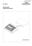
1
Guide for Installers
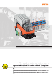
ADT645
Explosion-Safe Display Unit
Service XXL
Congratulations on choosing the quality and precision of METTLER TOLEDO. Proper use
according to these instructions and regular calibration and maintenance by our factorytrained service team ensure dependable and accurate operation, protecting your investment.
Contact us about a ServiceXXL agreement tailored to your needs and budget.
We invite you to register your product at
www.mt.com/productregistration
so we can contact you about enhancements, updates and important notifications concerning your METTLER TOLEDO product.
2
METTLER TOLEDO
Guide for Installers ADT645
Order number 44099370B
07/10
Contents
07/10
1
Safety precautions................................................................................................4
2
2.1
2.2
2.3
2.4
System overview..................................................................................................6
Using the ADT645 Display......................................................................................6
Supplied equipment...............................................................................................6
System configuration..............................................................................................6
Description of the components................................................................................7
3
3.1
3.2
3.3
3.4
3.5
Hardware installation...........................................................................................8
Notes on installing the ADT645 system....................................................................8
Wall mounting of ADT645 Display and ADT645 Keyboard ........................................9
Connections at the ADT645 Display.......................................................................10
Connections at the ADT645 Interface......................................................................11
Switching on and off............................................................................................12
4
4.1
4.2
Software installation..........................................................................................13
Installing the Touchscreen Software.......................................................................13
Software settings.................................................................................................16
5
5.1
5.2
Cleaning and inspection.....................................................................................22
Cleaning.............................................................................................................22
Inspection...........................................................................................................22
6
Troubleshooting..................................................................................................23
7
7.1
7.2
Technical data....................................................................................................24
ADT645 Display and ADT645 Keyboard.................................................................24
ADT645 Interface.................................................................................................25
8
8.1
8.2
Declarations of conformity..................................................................................26
ADT645 Display Declaration of Conformity.............................................................26
ADT645 Interface Declaration of Conformity............................................................28
9
9.1
9.2
Annex................................................................................................................30
Disposal.............................................................................................................30
FCC notice..........................................................................................................30
Order number 44099370B
METTLER TOLEDO
Guide for Installers ADT645
3
Safety precautions
1
4
Safety precautions
▲▲ The ADT645 Display is approved for operation in Zone 0 hazardous areas.
▲▲ Particular care is required when using weighing systems with the ADT645 Display in
hazardous areas. The code of practice is oriented to the "Safe Distribution" concept
drawn up by METTLER TOLEDO.
METTLER TOLEDO
Competence
▲▲ The ADT645 Display may only be installed, maintained and repaired by authorized
METTLER TOLEDO service personnel.
Ex approval
▲▲ No modifications may be made to the device and no repair work may be performed
on the modules. Any scale or system modules that are used must comply with the
specifications contained in the installation instructions. Non-compliant equipment
jeopardises the intrinsic safety of the system, cancels the "Ex" approval and renders
any warranty or product liability claims null and void.
▲▲ The safety of the weighing system is only guaranteed when the weighing system is
operated, istalled and maintained in accordance with the respective instructions.
▲▲ Also comply with the following:
–– the instructions for the system modules and scales,
–– the regulations and standards in the respective country,
–– the statutory requirement for electrical equipment installed in hazardous areas in
the respective country,
–– all instructions related to safety issued by the owner.
▲▲ The explosion-protected weighing system must be checked to ensure compliance with
the requirements for safety before being put into service for the first time, following any
service work and every 3 years, at least.
Operation
▲▲ Prevent the build-up of static electricity. Always wear suitable working clothes when
operating or performing service work in an hazardous area.
▲▲ Do not use protective covers for the devices.
▲▲ Avoid damage to the system components.
Guide for Installers ADT645
Order number 44099370B
07/10
Installation
07/10
▲▲ Only install or perform maintenance work on the weighing system in the hazardous
areas if the following conditions are fulfilled:
–– the intrinsically safe characteristic values and zone approval for individual components are in accordance with one other,
–– the owner has issued a permit ("spark permit" or "fire permit"),
–– the area has been rendered safe and the owner`s safety co-ordinator has confirmed
that there is no danger,
–– the necessary tools and any required protective clothing are provided (danger of
build-up of static electricity)
▲▲ The certification documents (certificates, manufacturer`s declarations) must be present.
▲▲ Route the cables so that they cannot move. Protect the cables against possible damage.
▲▲ Only route the cables into the housing of the system modules via a suitable cable
gland.
Order number 44099370B
METTLER TOLEDO
Guide for Installers ADT645
5
System overview
2
System overview
2.1
Using the ADT645 Display
The ADT645 Display is a TouchScreen display used for remote operation of a PC. The
ADT645 Display, scale and optional keyboard and mouse are placed in the hazardous
area and are connected via a ADT645 cable to the ADT645 Interface and to the PC. Interface and PC are placed in the safe area.
2.2
Supplied equipment
•
•
•
•
•
•
•
ADT645 Display with ADT645 cable and ADT645 keyboard (trackball optional)
ADT645 Interface
1 x 1.8 m VGA cable
3 x 1.8 m serial cables
1 x 1.8 m mains cable (regional options)
1 x 10 m / 20 m cable (optional)
TouchScreen software (optional)
Note
Contact your METTLER TOLEDO representative for accessories and options available.
2.3
6
METTLER TOLEDO
Guide for Installers ADT645
System configuration
Order number 44099370B
07/10
2.4
ADT645 Display
ADT645 Keyboard
Description of the components
The ADT645 Display and ADT645 Keyboard are Intrinsically Safe Apparatus of Category 1.
They are suitable for use in Zone 0 hazardous areas.
Approvals
Temperature range
IECEx BAS 08.0051X Ga Ex ma ia IIB T5
Baseefa08ATEX167X II 1G Ga Ex ma ia IIB T5
FM
Class I, Division 1, Groups C, D, T5
0 °C to + 40 °C
Connections
1
2
3
4
5
6
ADT645 Interface
On/off switch
ADT645 Interface
ADT645 Keyboard
ADT645 Mouse
Scale power
Scale serial interface
The ADT645 Interface is an Associated Intrinsically Safe Apparatus of Category 1.
It is suitable for supplying Zone 0 equipment.
Approvals
IECEx BAS 08.0052 Baseefa08ATEX168
FM
(Ga) [Ex ia] IIB
II (1) G (Ga) [Ex ia] IIB
Class I, Division 1, Groups C, D
Connections
1
1
2
3
4
5
07/10
Order number 44099370B
2
3
4
5
PC (to connect to the VGA port and one USB port on the PC)
Monitor (to connect a monitor in the safe area)
TouchScreen (to connect to COM2 on the PC)
Com Port (to connect to COM1 on the PC)
Mains
METTLER TOLEDO
Guide for Installers ADT645
7
Hardware installation
8
3
Hardware installation
3.1
Notes on installing the ADT645 system
WARNING!
Electric shock hazard!
▲▲ Connect the units with certified cables approved by METTLER TOLEDO only.
▲▲ Before operating the equipment make sure that the mains power cable to the ADT645
Interface case contains an earth, that is connected to the safe-area power-supply
earth. The cable must comply with the national requirements.
CAUTION!
Damage to the units!
▲▲ Before connecting the equipment to the power supply, connect all cables to the
ADT645 Interface and the ADT645 Display.
▲▲ Do not connect the equipment if the required voltage value is different to the local
voltage.
▲▲ Allow only trained personnel to install and operate the equipment.
METTLER TOLEDO
3.1.1
Routing principles
➜➜ Route the cables in a way that, i.e., sharp/rough edges or extreme heat cannot damage them.
➜➜ Make sure that the cables are long enough to prevent tensions on wires, terminals,
connections, junctions and supports.
➜➜ Put grommets on the cables that pass through metal enclosures.
➜➜ Cable and connectors are identical, compatible with both interface and display ports
allowing the cable to be installed either way round.
3.1.2
Installation order
1. Position the ADT645 Display and the ADT645 Keyboard.
2. Connect the scale to the ADT645 Display.
3. Connect ADT645 Display and ADT645 Interface.
4. Connect the PC and peripherals to the ADT645 Interface.
5. Connect the ADT645 Interface to the power supply.
6. Switch on the ADT645 Display.
3.1.3
Storage
➜➜ Store packaged units in a cool, dry area at a temperature of –20 °C to 50 °C.
➜➜ Keep units away from any heat source or direct sunlight.
➜➜ Make sure that the units are not exposed to vibrations or shocks.
Guide for Installers ADT645
Order number 44099370B
07/10
3.2
Wall mounting of ADT645 Display and ADT645 Keyboard
CAUTION!
Display and keyboard weigh approx. 10 kg. When mounting display and keyboard to
the wall pay attention to the following:
▲▲ Work must be undertaken by competent personnel.
▲▲ Adequate fixings must be ensured.
Drilling template
07/10
Order number 44099370B
METTLER TOLEDO
Guide for Installers ADT645
9
Hardware installation
3.3
Connections at the ADT645 Display
3.3.1
Connecting the scale
1. Mount the scale in the hazardous area as described in the scale's Installation Information.
2. Route the scale cables to the ADT645 display.
3. Connect the power and signal cables of the scale to the connectors (5, 6) on the rear
of the ADT645 Display.
4. In case a stand is mounted, adjust the mounting feet on the back of the stand until
the display is stable and the display level as well as the viewing angle are correct.
3.3.2
Connecting the interface cable
1. Align cable plug and socket: the lugs on the plug must match the lugs on the socket,
with the big lug at top.
2. Insert and twist locking ring.
10
METTLER TOLEDO
Guide for Installers ADT645
Order number 44099370B
07/10
3.4
Connections at the ADT645 Interface
3.4.1
Connecting the ADT645 Display to the ADT645 Interface
CAUTION
Damages to the unit
▲▲ The ADT645 Interface must only be installed in the safe area.
▲▲ Do not connect the interface safe area connections to the PC and peripheral equipment
if the voltage supply is higher than 253 V r.m.s.
1. Align cable plug and socket: the lugs on the plug must match the lugs on the socket,
with the big lug at top.
2. Insert and twist locking ring.
3.4.2
Connecting the PC and peripherals to the ADT645 Interface
1
2
3
4
5
1. Connect the VGA cable from the VGA port and a USB port on the PC to the PC socket (1)
of the ADT645 Interface.
2. Connect COM1 from the PC to the Com Port socket (4) and COM2 to the TouchScreen
socket (3).
07/10
Order number 44099370B
METTLER TOLEDO
Guide for Installers ADT645
11
Hardware installation
3.4.3
Connecting the power supply
1
2
3
4
5
1. Connect the power cord to the ADT645 Interface (5) and a mains outlet.
2. Connect the PC to a mains outlet.
3.5
Switching on and off
Prerequisite
ADT645 Interface and PC are connected to the mains.
➜➜ Press the on/off switch (1) on the back of the display.
Notes
• Switch the system off if you do not use it for a longer period of time.
• Power settings on the PC should be set to switch off the monitor after 1 hour.
Damage caused to the display backlight by failure to do this may invalidate warranty.
12
METTLER TOLEDO
Guide for Installers ADT645
Order number 44099370B
07/10
4
Software installation
4.1
Installing the Touchscreen Software
1. Browse to the drive containing the ADT645 CD, e.g. D:.
2. Run the file Setup.exe.
• The folder C:\Program Files\Touchscreen Software will be created.
• The icon Touchscreen Software 1.0 will be placed on the desktop.
07/10
Order number 44099370B
METTLER TOLEDO
Guide for Installers ADT645
13
Software installation
• The shortcut MA7_Driver will be placed in the startup folder of the Start menu and in
the folder Touchscreen Software 1.0 in the Start menu.
Note
• If the software fails to install correctly it will be necessary to manually install the desktop
icon and start menu shortcuts, see sections 4.1.1 and 4.1.2.
• If the software is installed correctly, proceed with section 4.1.3.
4.1.1
14
METTLER TOLEDO
Guide for Installers ADT645
Creating a desktop shortcut for the Touchscreen Software
1. Open the Program Files\Touchscreen Software folder.
2. Move the cursor over the MA7_Control_En icon.
3. Click the right mouse button and select Create Shortcut.
Order number 44099370B
07/10
• When using Windows Vista this shortcut will be automatically copied to the desktop.
• When using Windows XP, Windows 2000 or Windows 98 copy the shortcut "Touchscreen Control" to the desktop.
4.1.2
07/10
Adding the driver to the "Startup" folder
1. Close "C:\Program Files".
2. Go to the start menu and find "Programs/Startup".
3. Click the right mouse button and select "Open".
Order number 44099370B
METTLER TOLEDO
Guide for Installers ADT645
15
Software installation
The Startup folder will be opened in a new window.
4. Create a shortcut to the file MA7_Driver.
5. Copy the shortcut to the Startup folder.
16
METTLER TOLEDO
4.1.3
Finishing installation
1. Close all open folders and remove the CD from the CD drive.
2. Restart the PC.
4.2
Software settings
4.2.1
Opening the Touchscreen Control Panel
1. Close down all other programs until you return to the Windows Desktop.
2. Open the Touchscreen Control Panel by selecting the MA7_Control_En icon on the
desktop.
The following screen will appear.
Guide for Installers ADT645
Order number 44099370B
07/10
07/10
4.2.2
Selecting the Com Port
1. Select the Comms tab.
2. Select the Port that the touchscreen is connected to.
3. Set the baud rate to 9600.
4. Check Open in the Status section.
The screen should appear as it does in the picture below.
4.2.3
Altering the Sensitivity
➜➜ Select the Sense tab.
Order number 44099370B
METTLER TOLEDO
Guide for Installers ADT645
17
Software installation
Coarse Sensitivity
Press Threshold
Finger Pressure
... is used to set the sensitivity of an applied touch. If the slider is set to the right, the touchscreen is more sensitive to an applied touch to the
surface.
... is used to set the activation point of an applied touch.
illustrates the strength of signal the touchscreen is receiving from an applied touch. The
signal strength must pass the Press Threshold to register a touch.
When there is no touch applied, the Finger Pressure will show a slight jitter.
Setting the sensitivity and activation threshold of the Touchscreen
1. Lightly touch the touchscreen.
2. Adjust the Coarse Sensitivity slider so that the Finger Pressure indicator always
passes the Press Threshold.
3. Touch the screen in several places to check that the Finger Pressure always passes
the Press Threshold.
4. If the background level is above the Finger Pressure, adjust the Press Threshold
slider and repeat the process of adjusting the Coarse Sensitivity.
The positions shown in the picture above should give a reasonable response from the
touchscreen.
4.2.4
Calibration
1. Select the Calibration tab.
2.
3.
4.
5.
Select the Start Calibration button.
Touch the centre of each target in turn and hold your finger steady in place.
Remove your finger only when the next target appears.
Once all three targets have disappeared the calibration is complete.
Note
The calibration sequence of three targets can be exited at any time by either holding your
finger on the red box in the centre of the screen or by presing the Esc key on the keyboard.
18
METTLER TOLEDO
Guide for Installers ADT645
Order number 44099370B
07/10
Step 1
Step 2
Step 3
4.2.5
07/10
Setting the Mouse Mode
1. Select the Output tab.
2. Select the Touch screen’s mouse control from the list.
For standard mouse operation select Select/Move/Release.
3. Check Enable selected control to enable the mouse operation.
Order number 44099370B
METTLER TOLEDO
Guide for Installers ADT645
19
Software installation
4.2.6
Checking the Touchscreen Operation
1. Select the Graph tab.
The lines show the Finger Pressure measured on the horizontal and vertical edges
of the screen.
The position of the lines will move as your finger moves around the screen.
2. Select the Monitor tab
Moving your finger round the screen will result in a red line showing the movement
round the screen.
20
METTLER TOLEDO
Guide for Installers ADT645
Order number 44099370B
07/10
4.2.7
Setting the Edge Gain
• If, after calibration, the cursor will not reach the edges of the touchscreen, a small
amount of edge gain can be set.
• This can be done by moving the sliders away from the centre: the further the sliders are
moved, the higher the gain.
• Moving the sliders by 2~3mm is usually sufficient.
1. Select the Edge tab.
2. Move the sliders.
4.2.8
Saving the Touchscreen Control Settings
Note
• The Touchscreen Control program does NOT automatically save the settings on Exit.
• The settings must be manually saved before exit.
1. Select File from the Menu.
2. Select Save.
3. Select Exit.
07/10
Order number 44099370B
METTLER TOLEDO
Guide for Installers ADT645
21
Cleaning and inspection
5
Cleaning and inspection
5.1
Cleaning
DANGER!
Electric shock hazard due to ingress of moisture!
▲▲ Before cleaning:
–– shutdown the PC via the ADT645 Display
–– pull out the power plug to disconnect the system from the power supply
Further notes on cleaning
➜➜ Use a damp cloth and only non solvent based cleaners.
➜➜ Do not use any acids, alkalis or solvent based cleaners.
➜➜ Do not clean the unit using a high-pressure cleaning unit or under running water.
➜➜ Follow all the relevant instructions regarding cleaning intervals and permissible cleaning agents.
5.2
Inspection
The ADT645 parts are not serviceable and cannot be repaired by the user.
➜➜ Contact your supplier if damage and/or malfunction are discovered during installation
or operation of the system.
22
METTLER TOLEDO
5.2.1
Inspection intervals
➜➜ Inspections are to be carried out annually, as a minimum, to ensure the continued
safe operation of the unit.
5.2.2
Inspection procedure
➜➜ Let a METTLER TOLEDO trained technician carry out the inspection.
➜➜ If damage and/or malfunction of the unit are discovered during the inspection, contact
your METTLER TOLEDO representative.
Guide for Installers ADT645
Order number 44099370B
07/10
6
Problem
Display is blank
Troubleshooting
Possible cause
• Cables are not correctly connected
• Cable is damaged
• Units are not switched on
Display is dim or distorted
Touchscreen does not work
Scale does not work
• Cause is not known
• Cause is not known
• Cables are not correctly connected
• Cable is damaged
• Software not installed correctly
• Cause is not known
• Cables are not correctly connected
• Cable is damaged
• Port settings are not correctly
set
• Cause is not known
Keyboard does not work
• Cables are not correctly connected
• Cable is damaged
• Cause is not known
Some keys on the keyboard do not • Keyboard is damaged
work
Software does not work correctly
• Cause is not known
Physical damage
• Cause is not known
Trackball (if fitted) does not work
• Cables are not correctly connected
• Cable is damaged
• Cause is not known
07/10
Order number 44099370B
Remedy
➜➜ Check if all cables are correctly connected
➜➜ Check all cables for physical damage
➜➜ Ensure that all cables are correctly connected
before powering on
➜➜ Check that both the ADT645 Interface and the
PC are powered on
➜➜ Contact your METTLER TOLEDO representative
➜➜ Contact your METTLER TOLEDO representative
➜➜ Check if all cables are correctly connected to
the ADT645
➜➜ Check all cables for physical damage
➜➜ Check that the software has been installed and
configured according to the instruction manual
➜➜ Contact your METTLER TOLEDO representative
➜➜ Check if all cables are correctly connected to
the ADT645
➜➜ Check all cables for physical damage
➜➜ Check that the port settings are correctly set
on the peripheral and the computer (the serial
interface does not support handshaking)
➜➜ Contact your METTLER TOLEDO representative
➜➜ Check if all cables are correctly connected to
the ADT645
➜➜ Check all cables for physical damage
➜➜ Contact your METTLER TOLEDO representative
➜➜ Replace the keyboard
➜➜ Contact supplier of PC and/or software
➜➜ Contact supplier of PC and/or software
➜➜ Check if all cables are correctly connected to
the ADT645
➜➜ Check all cables for physical damage
➜➜ Contact your METTLER TOLEDO representative
METTLER TOLEDO
Guide for Installers ADT645
23
Technical data
7
Technical data
7.1
ADT645 Display and ADT645 Keyboard
Ignition protection type
Temperature range
Preinstalled cable
Serial port output parameters
Scale power supply output
paramters
Weight
IECEx BAS 08.0051X
Baseefa08ATEX167X
FM
Operation
Storage
10 m
U0 = 11.7 V
I0 = 0.092 A
P0 = 0.266 W
U0 = 12.6 V
I0 = 0.34 A
P0 = 3.74 W
ADT645 Display
ADT645 Keyboard
Ga Ex ma ia IIB T5
II 1G Ga Ex ma ia IIB T5
Cl. I, Div. 1, Groups C, D, T5
0 °C to +40 °C
–20°C to +50°C
8.0 kg
1.5 kg
Dimensional drawings
50.4 mm
340 mm
370 mm
22 mm
140 mm
370 mm
24
METTLER TOLEDO
Guide for Installers ADT645
Order number 44099370B
07/10
140.0
440.0
32.5
39.4
7.2
ADT645 Interface
Ignition protection type
Temperature range
Supply voltage
Power consumption
Weight
IECEx BAS 08.0052 (Ga) [Ex ia] IIB
Baseefa08ATEX168
II (1) G (Ga) [Ex ia] IIB
FM
Cl. I, Div. 1, Groups C, D
Operation
0 °C to +40 °C
Storage
–20°C to +50°C
90-264 V AC, 50-60Hz
25 W typ.
3.5 kg
Dimensional drawing
07/10
Order number 44099370B
METTLER TOLEDO
Guide for Installers ADT645
25
Declarations of conformity
8
Declarations of conformity
8.1
ADT645 Display Declaration of Conformity
The ADT645 Display is an Intrinsically Safe Apparatus, Category 1, suitable for use in
Zone 0 hazardous areas.
The manufacturer hereby declares with sole responsibility that the ADT645 Display and
ADT645 Keyboard (with trackball option) comply with the following international and EU
directives and standards:
89/336EEC
EMC
Emissions EN 61000-6-4 2007
Immunity EN 61000-6-1 2007
Immunity EN 61000-6-2 2005
EN60529: 1992
FCC/CFR 47:15 FCC/CFR 47:Part 15:2009
EN60529:1992
94/9/EEC ATEX EN 60079-0:2006
EN 60079-11:2007
EN 60079-18:2004
EN60079-26:2007
IECEx
IEC 60079-0:2004
Ed: 4
IEC 60079-11:2006
Ed: 5.0
IEC 60079-18: 2004
Ed: 2.0
IEC60079-26:2006
Ed: 2
Notified Body
FM
FM3600: 11/98
FM3610: 10/99
ANSI/ISA-60079-18 (12.23.01)2005
Notified Body
Special Conditions
Industrial Environment
Residential, commercial and light industrial
Industrial Environment
Ingress Protection: IP54
Unintentional radiators
Ingress Protection: IP54
Electrical apparatus for explosive gas atmospheres
– Part 0: General requirements
Electrical apparatus for explosive gas atmospheres
– Part 11: Intrinsic safety 'i'
Electrical apparatus for explosive gas atmospheres
– Part 18: Encapsulation 'm'
Explosive atmospheres. Equipment with equipment protection level
(EPL) Ga
Electrical apparatus for explosive gas atmospheres
– Part 0: General requirements
Electrical apparatus for explosive gas atmospheres
– Part 11: Intrinsic safety 'i'
Electrical apparatus for explosive gas atmospheres
– Part 18: Encapsulation 'm'
Explosive atmospheres. Equipment with equipment protection level
(EPL) Ga
Baseefa Ltd. Ref No: - 1180
Approval Standard for Electric Equipment for use in Hazardous
(Classified) Locations – General Requirements
Approval Standard for Intrinsically Safe Apparatus and Associated
Apparatus for Use in Class I, II, & III, Division 1, and Class I,
Zone 0 & 1 Hazardous (Classified) Locations
Electrical Apparatus for Use in Class I, Zone 1 Hazardous
(Classified) Locations Type of Protection – Encapsulation
FM Approvals Ltd.
Ambient Temperature 0 °C to +40 °C
The serial port available to the user in the hazardous area has the following output
parameters:
U0
11.7 V
I0
0.092 A
P0
0.266 W
26
METTLER TOLEDO
Guide for Installers ADT645
Order number 44099370B
07/10
Intecpc Ltd, Rupert House, London Rd Sth, Poynton, Cheshire, SK12 1PQ,
United Kingdom
22/07/2010
Mark Russell
Managing Director
07/10
Order number 44099370B
Andy Griffin
Technical Director
METTLER TOLEDO
Guide for Installers ADT645
27
Declarations of conformity
8.2
ADT645 Interface Declaration of Conformity
The ADT645 Interface is Associated Intrinsically Safe Apparatus, Category 1, suitable for
supplying Zone 0 equipment.
The manufacturer hereby declares with sole responsibility that the ADT645 Interface complies with the following international and EU directives and standards:
89/336EEC
EMC
FCC/CFR 47:15
94/9/EEC ATEX
Emissions EN 61000-6-4 2007
Immunity EN 61000-6-1 2007
Immunity EN 61000-6-2 2005
FCC/CFR 47:Part 15:2009
EN 60079-0:2006
EN 60079-11:2007
EN60079-26:2007
IECEx
IEC 60079-0:2004
Ed: 4
IEC 60079-11:2006
Ed: 5.0
IEC60079-26:2006
Ed: 2
Notified body
FM
FM3600: 11/98
FM3610: 10/99
Notified Body
Special Conditions
Industrial environment
Residential, commercial and light industrial
Industrial Eenvironment
Unintentional radiators
Electrical apparatus for explosive gas atmospheres
– Part 0: General requirements
Electrical apparatus for explosive gas atmospheres
– Part 11: Intrinsic safety 'i'
Explosive atmospheres. Equipment with equipment protection level
(EPL) Ga
Electrical apparatus for explosive gas atmospheres
– Part 0: General requirements
Electrical apparatus for explosive gas atmospheres
– Part 11: Intrinsic safety 'i'
Explosive atmospheres. Equipment with equipment protection level
(EPL) Ga
Baseefa Ltd. Ref No: - 1180
Approval Standard for Electric Equipment for use in Hazardous
(Classified) Locations – General Requirements
Approval Standard for Intrinsically Safe Apparatus and Associated
Apparatus for Use in Class I, II, & III, Division 1, and Class I,
Zone 0 & 1 Hazardous (Classified) Locations
FM Approvals Ltd.
None
-
28
METTLER TOLEDO
Guide for Installers ADT645
Order number 44099370B
07/10
Intecpc Ltd, Rupert House, London Rd Sth, Poynton, Cheshire, SK12 1PQ,
United Kingdom
22/07/2010
Mark Russell
Managing Director
07/10
Order number 44099370B
Andy Griffin
Technical Director
METTLER TOLEDO
Guide for Installers ADT645
29
Annex
9
Annex
9.1
Disposal
In conformance with the European Directive 2002/96/EC on Waste Electrical and Electronic Equipment (WEEE), this device must not be disposed of in domestic waste. This
also applies to countries outside the EU as per their specific regulations.
➜➜ Please dispose of this product in accordance with local regulations at the collecting
point specified for electrical and electronic equipment.
If you have any questions, please contact the responsible authority or the distributor from
which you purchased this device.
Should this device be passed on to other parties (for private or professional use), the
content of this regulation must also be related.
Thank you for your contribution to environmental protection.
9.2
FCC notice
This equipment has been tested and found to comply with the limits for a Class A digital
device, pursuant to both Part 15 of the FCC Rules and the radio interference regulations
ot the Canadian Department of Communications. These limits are designed to provide a
reasonable protection against harmful interference when the equipment is operated in a
commercial environment. This equipment generates, uses and can radiate radio frequency
energy and, if not installed and used in accordance with the user manual, may cause
harmful interference to radio communications. Operation of this equipment in a residential
area is likely to cause harmful interference, in which case the user will be required to correct the interference at his own expense.
30
METTLER TOLEDO
Guide for Installers ADT645
Order number 44099370B
07/10
07/10
Order number 44099370B
METTLER TOLEDO
Guide for Installers ADT645
31
www.mt.com/service
For more information
Mettler-Toledo AG
CH-8606 Greifensee
Switzerland
Tel. + 41 44 944 22 11
Fax+ 41 44 944 30 60
Subject to technical changes
© 07/2010 Mettler-Toledo AG
Printed in Switzerland
Order number 44099370B