1
Bustechnology
System description ANTARES Remote I/O System
Ê
ÊÊÊÊÊÊÊÊÊÊÊÊÊÊÊÊÊÊÊÊÊÊÊÊÊÊÊÊÊÊÊÊÊÊÊÊÊÊÊÊÊÊÊÊÊÊÊÊÊÊÊÊÊÊÊÊÊÊÊÊÊÊÊÊÊÊÊÊÊÊÊÊÊÊÊÊÊÊÊÊÊÊÊÊÊÊÊÊÊÊÊÊÊÊÊÊÊÊÊÊÊÊÊÊÊÊÊVÕiÌÊ°Ê££x£Ç{ÇäääÓ
Ê
ÊÊÊÊÊÊÊÊÊÊÊÊÊÊÊÊÊÊÊÊÊÊÊÊÊÊÊÊÊÊÊÊÊÊÊÊÊÊÊÊÊÊÊÊÊÊÊÊÊÊÊÊÊÊÊÊÊÊÊÊÊÊÊÊÊÊÊÊÊÊÊÊÊÊÊÊÊÊÊÊÊÊÊÊÊÊÊÊÊÊÊÊÊÊÊÊÊÊÊÊÊÊ,iÛÃÊäÊÉÊ-Ì>ÌÕÃ\ÊÕÞ]ÊÓ{Ì
ÊÓä£Î
System Description - Translation
Remote I/O-Systeme
ANTARES
ATEX / IECEx
Zone 1 and Zone 21
Document no. 11-5174-7D0002
Revision 0 / July 24th, 2013
Reservation: Technical data subject to change without notice. Changes, errors
and misprints may not be used as a basis for any claim for damages.
BARTEC GmbH
Max-Eyth-Straße 16
97980 Bad Mergentheim
Germany
Technical data subject to change without notice.
Issue 07/2013
Contents
Pages
ENGLISH
1-34
Phone: +49 7931 597-0
Fax:
+49 7931 597-119
Contact:
[email protected]
Download:
www.bartec.de/automation-download
Page 1 of 35
ANTARES Remote I/O Systems
System Description
The System Description is a constituent part of the product and must be kept in the direct vicinity of
the system and be accessible at all times to the installation, operating and maintenance personnel.
It contains important information, safety instructions and test certificates that are necessary for perfect
functioning when operating and handling the devices. It is addressed to technically qualified
personnel.
Familiarity with and the technically perfect implementation of the safety instructions and warnings
described in this manual are preconditions for safe installation and commissioning. The safety notes
and warnings in this documentation are given in a general way and only qualified personnel will have
the necessary specialised knowledge to interpret and implement them correctly in specific individual
cases.
Safety Instructions
Only the responsible qualified personnel may install and connect the product and its components.
Any subsequent modification of the product is strictly prohibited and will exempt BARTEC from liability
for defects or any further liability.
The Remote I/O systems ANTARES may be operated only if they are clean and free of damage.
The generally applicable statutory rules and other binding directives on workplace safety, accident
prevention and environmental protection must be adhered to.
Danger, Warning and Note Symbols in the System Description
Danger!
Non-observance leads to death or serious physical injury.
The necessary safety measures must be taken.
Warning of damage to property and financial and penal disadvantages (e.g. loss of
Caution!
Attention!
Note
guarantee rights, liability etc.).
Important instructions and information on preventing disadvantageous behaviour.
Important instructions and information on effective, economical and environmentally
compatible handling.
Technical data subject to change without notice.
Issue 07/2013
Page 3 of 35
System Description
Remote I/O Systems
ANTARES
Contents
1
1.1
1.2
Special Features .............................................................................................................................. 5
Definition ......................................................................................................................................................... 5
Use for the Intended Purpose ......................................................................................................................... 5
2
2.1
2.2
2.2.1
2.2.2
2.2.3
Technical Data ................................................................................................................................. 6
Remote I/O Systems ANTARES ..................................................................................................................... 6
Devices and Components in the Remote I/O Systems ANTARES ................................................................. 7
RCU ANTARES .............................................................................................................................................. 8
Remote I/O Modules ANTARES ..................................................................................................................... 9
Accessories in the RCU ANTARES .............................................................................................................. 10
3
3.1
3.1.1
3.1.2
3.1.3
Construction .................................................................................................................................. 11
Possible Construction of the Remote I/O Systems ANTARES ..................................................................... 12
RCU ANTARES and Various Remote I/O Modules ANTARES .................................................................... 12
RCU ANTARES, Redundant RCU ANTARES and various Remote I/O Modules ANTARES ...................... 13
RCU ANTARES (also Singly Redundant), various Remote I/O Modules ANTARES and
Mounting Rail Transitional Section................................................................................................................ 14
Max. Quantity of Remote I/O Modules ANTARES ........................................................................................ 15
Determination of the temperature in and around the protective enclosure ................................................... 16
Maximum Quantity of Mounting Rail Transitional Sections and Maximum Length of
the Ext Bus cable and the Ext power cables ................................................................................................. 17
3.2
3.3
3.4
4
Labelling........................................................................................................................................ 18
5
5.1
5.2
5.3
5.4
5.4.1
5.4.2
5.4.2.1
5.4.2.2
5.4.2.3
5.5
5.6
5.6.1
5.6.2
5.6.3
5.6.4
5.7
5.7.1
5.7.2
5.7.3
Installing the Remote I/O Systems ANTARES ................................................................................. 20
Operating Position......................................................................................................................................... 20
Earthing ......................................................................................................................................................... 20
Strain Relief for the Connection Leads ......................................................................................................... 20
Installing ........................................................................................................................................................ 20
Installation on Mounting Rail ......................................................................................................................... 20
Mounting the ANTARES Remote I/O Systems ............................................................................................. 21
RCU ANTARES and Various ANTARES Remote I/O Modules .................................................................... 21
RCU ANTARES, Redundant RCU ANTARES and Various Remote I/O Modules ANTARES ...................... 22
RCU ANTARES (also Singly Redundant), various Remote I/O Modules ANTARES and
Mounting Rail Transitional Section................................................................................................................ 23
Special Conditions ........................................................................................................................................ 24
Installation in Zone 1 and Zone 2 .................................................................................................................. 24
Installation Space .......................................................................................................................................... 25
Calculation of the Ambient Temperature when Fitting into an Enclosure ..................................................... 26
Examples of Compact Construction in Zone 1 and Zone 2........................................................................... 27
Examples of Single-Unit Construction in Zone 1 and Zone 2 ....................................................................... 29
Installation in Zone 21 and Zone 22 .............................................................................................................. 30
Dimensions Ex-tD / Ex-tb Enclosure ............................................................................................................. 31
Examples of Compact Construction in Zone 21 and Zone 22....................................................................... 32
Example of Single-Unit Construction in Zone 21 and Zone 22 ..................................................................... 33
6
6.1
6.1.1
6.1.2
6.2
6.3
6.3.1
6.3.2
Installation / Commissioning.......................................................................................................... 34
Additional Interfaces in the Ex e Junction Box .............................................................................................. 34
SD Memory Card .......................................................................................................................................... 34
Passive USB Port.......................................................................................................................................... 34
Integration of the ANTARES Remote I/O systems in a Master Control ........................................................ 35
HOT SWAP ................................................................................................................................................... 35
Electronic Unit in the Remote I/O Modules ANTARES ................................................................................. 35
Head Module ANTARES ............................................................................................................................... 35
Technical data subject to change without notice.
Issue 07/2013
Page 4 of 35
Remote I/O Systems
ANTARES
System Description
1
1.1
Special Features
Definition
The Remote I/O System ANTARES consists of:
-
the Rail Control Unit (RCU) ANTARES (power supply and CPU), also singly redundant, including the bus
beginning and bus end module and a certified rail-mounted earth conductor terminal and
various Remote I/O Modules ANTARES with separate certification and accessories.
They can be distributed over a maximum of 4 metal mounting rails. They can be set up either in a compact
construction (1 or a maximum of 4 mounting rails with short mounting rail transitional sections) or in single-unit
construction (max. 4 mounting rails with mounting rail transitional sections).
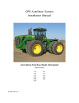
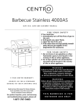
Illustration:
Example of a compact construction of an Remote I/O System ANTARES
in single operation, with an Remote I/O module ANTARES
1.2
Use for the Intended Purpose
The Remote I/O System ANTARES is intended for use within the explosion hazardous areas of Zones 1 and 2.
It also requires protection against mechanical damage!
The Remote I/O System ANTARES type 17-5184-xxxx/xxxx is intended for use within the explosion hazardous
areas of Zones 21 and 22. It requires protection by means of an enclosure with separate certification!
The Remote I/O systems ANTARES are connected by means of a communication interface with a master control
(PLC) in the safe area. This does not require an additional isolating repeater. There is a choice between the
following protocols:
- PROFIBUS-DP
- ProfiNet
- Modbus TCP
- Ethernet/IP
The Remote I/O systems ANTARES can process digital and analog process signals of intrinsically safe sensors or
actuators from the explosion hazardous areas of Zone 0 or Zone 20.
Typical areas of use are the chemical process industry, pharmaceutical, refinery, off-shore, oil and gas industries
with explosive gas atmospheres and machines and systems for explosive dust atmospheres.
Technical data subject to change without notice.
Issue 07/2013
Page 5 of 35
System Description
2
2.1
Remote I/O Systems
ANTARES
Technical Data
Remote I/O Systems ANTARES
More approvals and data are available at www.bartec-group.com.
Note
Ex protection type ATEX
Remote I/O system ANTARES
Ex protection type IECEx
Remote I/O system ANTARES
Mechanical construction
II 2 (1) G Ex d e [ia IIC/IIB Ga] IIC T4 Gb
Ex d e [ia IIC/IIB Ga] IIC T4 Gb
Either a protective device against mechanical damage or at
least an enclosure in a good industrial quality (not subject to
risks of electrostatic charging) (see chapter 5.6)
or
Ex protection type ATEX
Remote I/O System ANTARES
Type 17-5184-xxxx/xxxx
Mechanical Construction
II 2 (1) D Ex tb [ia Da] IIIC T100 °C Db oder
II 2 (1) D Ex tD [ia Da] A21 IP6X T100 °C
Enclosure with separate certification:
II 2 D Ex tb IIIC Db or
II 2 D Ex tD A21 IP6X
Ex protection type IECEx
Remote I/O System ANTARES
Type 17-5184-xxxx/xxxx
Mechanical Construction
Certification
Ex tb [ia Da] IIIC T100 °C Db oder
Ex tD [ia Da] A21 IP6X T100 °C
Ex tb IIIC Db or
Ex tD A21 IP6X
PTB 11 ATEX 2009 X
IECEx PTB 11.0051X
CE marking
Ambient temperature range
Rated voltage;
maximum DC voltage
Operating position
Technical data subject to change without notice.
Issue 07/2013
0044
-20 °C to +60°C (+50 °C)
The upper ambient temperature limit depends on the
Remote I/O Modules ANTARES used and the use of
distance modules (see chapter 3.1.1).
DC 24 V -15 %, +25 %; Um = DC 30 V
Vertical (e.g. on the wall, not on the floor),
cable glands for the connection module ANTARES at the
bottom
Page 6 of 35
System Description
Remote I/O Systems
ANTARES
Communication interfaces for the RCU ANTARES
- PROFIBUS-DP
- Ethernet (100BaseT with integrated switch)
Configuration
- Interface
- Software
Standards
in conformance to Directive 94/9/EC
in conformance to Directive 2004/108/EC (EMC)
Protocols
- PROFIBUS-DP up to 1.5 Mbit/s
- ProfiNet
- Modbus TCP
- Ethernet/IP
-
USB-Port (RCU ANTARES)
ANTARES Designer software
EN 60079-0:2009
EN 60079-11:2007
EN 60079-1:2007
EN 60079-7:2007
EN 61000-6-2:2005
EN 55011:2009
EN 61241-0:2006
EN 61241-11:2006
EN 60079-31:2009 or
EN 61241-1:2004
EN 61000-6-4:2007
Storage and transport temperature
-25 °C to +70 °C
Relative air humidity
5 to 95 %, non-condensing
Vibration (EN 60068-2-6)
2 g/7 mm; 5 Hz - 200 Hz in all 3 axes
Shock (EN 60068-2-27)
15 g, 11 ms in all 3 axes, ±3 shocks/direction
2.2
Devices and Components in the Remote I/O Systems ANTARES
The technical data for the devices and components in the Remote I/O systems ANTARES can be found in:
-
-
the "Operating instructions" for the
Rail Control Unit (RCU) ANTARES
Connection Module ANTARES, type 17-5164-9xx0/xxxx,
Head Module ANTARES, type 17-5174-1x0x/xxxx
the "Operating Instructions" for the
Remote I/O Module ANTARES … type 17-6143-1xxx/xxxx and
the "Installation Instructions" for the
ANTARES ExtSet 2 m / 10 m / 20 m.
The most important data are listed also in the following.
Technical data subject to change without notice.
Issue 07/2013
Page 7 of 35
System Description
2.2.1
Remote I/O Systems
ANTARES
RCU ANTARES
consisting of:
Connection Module ANTARES
type 17-5164-9xx0
and
Head Module ANTARES
type 17-5174-1x00
ATEX Ex protection type
II 2 G Ex d e [ib] IIC T4 Gb
IECEx Ex protection type
Ex d e [ib] IIC T4 Gb
Certification
PTB 11 ATEX 2009 X
IECEx PTB 11.0051X
CE marking
0044
Ambient temperature range
-20 °C to +60 °C
Rated voltage; maximum DC voltage
DC 24 V -15 %, +25 %; Um = DC 30 V
Protection class (EN 60529)
10+2-pole connectors
IP54,
IP30
Over voltage category to EN 60664-1
II
Contamination level
2
Installation on mounting rail
Metal, TH 35-15, DIN EN 60715
with earth conductor terminal
Max. power dissipation
- Single operation
- Redundant operation
Technical data subject to change without notice.
Issue 07/2013
(joined to the RCU ANTARES,
Remote I/O Module ANTARES or accessories)
II 2 G Ex eb IIC (with separate certification)
Rated connection capacity: 4 mm²
15 W
15 W + 7 W (Master + Slave) = 21 W
Page 8 of 35
System Description
2.2.2
Remote I/O Systems
ANTARES
Remote I/O Modules ANTARES
ATEX Ex protection type
II 2 (1) G Ex ib [ia IIC/IIB Ga] IIC T4 Gb and
II (1) D [Ex ia Da] IIIC
IECEx Ex protection type
Ex ib [ia IIC/IIB Ga] IIC T4 Gb
[Ex ia Da] IIIC
Certification
Type 17-6143-1001/00xx
Type 17-6143-1010/00xx
8DO PTB 11 ATEX 2014
8DO SCL IECEx PTB 11.0054
Type 17-6143-1002/00xx
Type 17-6143-1008/00xx
8DI-N PTB 11 ATEX 2015
16DI-N IECEx PTB 11.0055
Type 17-6143-1003/00xx
4TI
PTB 11 ATEX 2016
IECEx PTB 11.0058
Type 17-6143-1004/00xx
Type 17-6143-1005/00xx
8AI PTB 11 ATEX 2017
8AIH IECEx PTB 11.0059
Type 17-6143-1006/00xx
Type 17-6143-1007/00xx
4AIO PTB 11 ATEX 2018
4AIOH IECEx PTB 11.0061
CE marking
0044
Ambient temperature range
-20 °C to +60 °C (with distance module)
without restriction for
8DI-N and 16DI-N, 4TI
with restriction (see chapter 3.1.1) for
8DO and 8DO SCL, 8AI and 8AIH, 4AIO and 4AIOH
-20°C to +50°C (without distance module)
without restriction for all Remote I/O Modules ANTARES
Protection class (EN 60529)
IP30 (in the ANTARES system construction)
Snapping onto mounting rail
Metal, TH 35-15, DIN EN 60715
Accessories for the Remote I/O Modules ANTARES:
- Distance module, art. no. 05-0078-0106
Protection class (EN 60529)
IP 30 (in the ANTARES system construction)
Technical data subject to change without notice.
Issue 07/2013
Page 9 of 35
Remote I/O Systems
ANTARES
System Description
2.2.3
Accessories in the RCU ANTARES
System components
Earth connector terminal
Art. no. 03-7112-0017
To connect the local equipotential bonding conductor
Mounting rail TH 35-15
Art. no. 02-2010-0012
Length: 2 m, steel unperforated
Bus beginning module
Art. no. 05-0078-0084
Bus end module
Art. no. 05-0078-0085
For mechanically fastening the modules onto the mounting
rail and for connecting the internal databus
End plug
Art. no. 05-0078-0087
Supplied as standard with connection module, single operation
Connector bridge
Art. Nr. 05-0078-0086
for constructing a system in the redundancy operation
Distance module
Art. no. 05-0078-0106
in the Remote I/O Modules
8DO and 8DO SCL, 8AI and 8AIH, 4AIO and 4AIOH
for the temperature range -20 °C to +60 °C
Mounting rail transition section (ExtSet)
Rail beginning module Art. no. 05-0041-0319
Modules for extending the Remote I/O systems
Rail end module
Art. no. 05-0041-0320
Extension module
Art. no. 05-0078-0123
Ext power cable 1
(max. 20 m)
ÖLFLEX® Classic 100, 8 x 1.5 mm², pre-assembled
Ext power cable 2
(max. 20 m)
ÖLFLEX® Classic 100, 4 x 1.5 mm², pre-assembled
Ext bus cable
(max. 20 m)
UNITRONIC® BUS CAN, 2 x 2 x 0.34 mm², pre-assembled
Shortening set
Art. no. 05-0091-0164
for shortening the Ext power cable and ext bus cable
Strain relief set
Art. no. 05-0005-0067
Split ferrite bead
Art. no. 03-8388-0003
To reduce the interference voltage with Ethernet (cable
diameter: 4.5 to 8 mm)
Label holder
Art. no. 05-0705-0010
As base for the marking label
SD card
Type 17-28BE-F006/0002
For saving the RCU configuration data
Designer software
Type 17-28TF-0074
For configuring the Remote I/O System ANTARES
Further Accessories
Protection class (EN 60529)
Technical data subject to change without notice.
Issue 07/2013
IP 30 (in the ANTARES system construction)
Page 10 of 35
System Description
3
Remote I/O Systems
ANTARES
Construction
The central unit in the Remote I/O systems ANTARES is the Rail Control Unit (RCU) ANTARES. In these
systems, it may be available at most in a singly redundant form: (both devices) directly beside each other on a
common metal mounting rail.
Danger!
Two RCUs ANTARES (redundancy operation in the PROFIBUS-DP)
must always be aligned on a common mounting rail!
The RCU ANTARES consists of:
- Connection Module ANTARES type 17-5164-9xx0 and
- Head Module ANTARES type 17-5174-1x0x
The connection module ANTARES and head module ANTARES must have the
Attention! same communication interface (see type label).
Must include:
- TH35-15 mounting rail made of metal, DIN EN 60715
- separately certified Earth connector terminal - 1 for each mounting rail in the system - to connect the local
equipotential bonding conductor
- Bus beginning module and bus end module
Remote I/O Module ANTARES type 17-6143-1xxx/00xx
The Remote I/O Modules ANTARES must be fastened either onto the RCU ANTARES metal mounting rail or
onto up to 4 other metal mounting rails (with mounting rail transitional section).
Danger!
Inside explosion hazardous areas. It is not permissible to expose the various separately certified Remote
I/O Modules ANTARES type 17-6143-1xxx/00xx to processes that generate high charge levels or to flowing
particles.
Mounting rail transition section (ExtSet)
The mounting rail transition section is produced of 2 extension modules, a strain-relieved Ext bus cable for each,
Ext power cable 1 and Ext power cable 2, a separately certified earth connector terminal, and 1 rail end module
and 1 rail beginning module.
Danger!
An equipotential bonding conductor must be connected to each mounting rail!
RCU ANTARES, Remote I/O Modules ANTARES and extension module have 10+2-pole connectors (to supply
energy and transfer data), which must be connected firmly and directly to each other and to the 10-pole plug
connectors of the bus beginning module, bus end module, rail beginning module or rail end module in order to
obtain an enclosure unit satisfying protection class IP30.
Danger!
If there is a possibility of an explosive gas atmosphere, if it is not permissible the voltage supply must be
switched off before the 10+2-pole and 10-pole plugs are connected or disconnected.
Technical data subject to change without notice.
Issue 07/2013
Page 11 of 35
Remote I/O Systems
ANTARES
System Description
3.1
Possible Construction of the Remote I/O Systems ANTARES
3.1.1
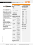
RCU ANTARES and Various Remote I/O Modules ANTARES
Illustration of an example up to
max. +60°C
Danger!
Item
Quantity
Designation
Art. no.
1
1x
Earth connector terminal
03-7112-0017
2
1x
Bus beginning module
05-0078-0084
3
1x
Head module
Type 17-5174-1x0x
4
1x
Connection module
Type 17-5164-9xx0
5
x
05-0078-0106
6
x
7
x
Distance module
Remote I/O Module
8DO or 8DO SCL, 8AI or 8AIH, 4AIO or 4AIOH
Remote I/O Module 8DI-N, 16DI-N, 4TI,
8
1x
Bus end module
05-0078-0085
9
1x
TH 35-15 mounting rail
02-2010-001x
Type 17-6143-1xxx/0000
Type 17-6143-1xxx/0000
A distance module art. no. 05-0078-0106 must be installed on the left and right of the ANTARES Remote
I/O modules: 8DO and 8DO SCL, 8AI and 8AIH, 4AIO and 4AIOH!
Note
Exception: it is not necessary to install a distance module between the ANTARES Remote I/O modules
8DO and 8DO SCL, 8AI and 8AIH, 4AIO and 4AIOH and a bus end module or an extension module.
Note
In the ambient temperature range -20°C to +50°C, it is also permissible to operate the ANTARES Remote
I/O modules 8DO and 8DO SCL, 8AI and 8AIH, 4AIO and 4AIOH without distance modules.
Technical data subject to change without notice.
Issue 07/2013
Page 12 of 35
Remote I/O Systems
ANTARES
System Description
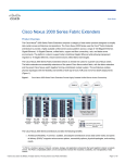
3.1.2
RCU ANTARES, Redundant RCU ANTARES and various Remote I/O Modules ANTARES
Example:
Illustration of an example up to
max. +50°C
Item
1
Quantity
1x
Designation
Earth connector terminal
Art. no.
03-7112-0017
2
1x
Bus beginning module
05-0078-0084
3
2x
Head module
Type 17-5174-110x
4
1x
Connector bridge
05-0078-0086
5
2x
6
X
7
1x
Connection module
Type 17-5164-91x0
ANTARES Remote I/O module 8DO or 8DO SCL,
Type 17-6143-1xxx/0000
8DI-N, 16DI-N, 4TI, 4AIO or 4AIOH, 8AI or 8AIH
Bus end module
05-0078-0085
8
1x
TH 35-15 mounting rail
Technical data subject to change without notice.
Issue 07/2013
02-2010-001x
Page 13 of 35
Remote I/O Systems
ANTARES
System Description
3.1.3 RCU ANTARES (also Singly Redundant), various Remote I/O Modules ANTARES and Mounting Rail
Transitional Section
Example:
Illustration of an example
up to max. +50°C
Item
Quantity
Designation
Art. no.
1
3x
Earth connector terminal
03-7112-0017
2
1x
Bus beginning module
05-0078-0084
3
1x
Head module
Type 17-5174-1x0x
4
1x
5
X
6
2x
Connection module
Type 17-5164-9xx0
ANTARES Remote I/O module 8DO or 8DO SCL, 8DI-N,
Type 17-6143-1xxx/0000
16DI-N, 4TI, 4AIO or 4AIOH, 8AI or 8AIH
Extension module
05-0078-0123
7
1x
Rail end module
05-0041-0320
8
1x
Ext power cable 1
05-0061-046x
9
1x
Ext power cable 2
05-0061-046x
10
1x
Ext bus cable
05-0061-046x
11
1x
Strain relief set
05-0005-0067
12
1x
Rail beginning module
05-0041-0319
13
1x
Bus end module
05-0078-0085
14
2x
TH 35-15 mounting rail
02-2010-001x
Technical data subject to change without notice.
Issue 07/2013
Page 14 of 35
Remote I/O Systems
ANTARES
System Description
3.2
Max. Quantity of Remote I/O Modules ANTARES
The RCU ANTARES (single or redundancy operation) is able to manage up to 32 Remote I/O Modules
ANTARES and provides a max. 74 W of power for these. The table below lists the total power consumption of
various Remote I/O Modules ANTARES. The max. possible quantity of the I/O Modules can be calculated by
adding the total power consumption of the fitted I/O Modules.
A choice of 9 various Remote I/O Modules ANTARES is available:
Designation
8DI-N
16DI-N
8DO
8DO SCL
8AI
8AIH
4AIO
4AIOH
4TI
Type
(8 Digital In NAMUR)
(16 Digital In NAMUR)
(8 Digital Out, 24 V)
(8 Digital Out, single current limit)
(8 Analog in)
(8 Analog in HART)
(4 Analog in/Out)
(4 Analog in/Out HART)
(4 Temperature in)
17-6143-1002
17-6143-1008
17-6143-1001
17-6143-1010
17-6143-1004
17-6143-1005
17-6143-1006
17-6143-1007
17-6143-1003
PModule
[W]
1.8
2.4
6.5
6.6
6.4
6.5
4.0
4.0
1.6
PVModule
[W]
1.5
2.2
3.5
3.5
3.5
3.5
2.5
2.5
1.5
PModule [W] = Total power consumption, PV Module [W] = Power dissipation
Σ PModule ≤ 74 W
Note
The order in which various Remote I/O Modules ANTARES are installed is not important.
Technical data subject to change without notice.
Issue 07/2013
Page 15 of 35
System Description
3.3
Remote I/O Systems
ANTARES
Determination of the temperature in and around the protective enclosure
The user must him/herself calculate and ensure the appropriate difference between the temperature in the
protective enclosure and that around it, depending on the particular protective enclosure being used.
Caution!
The maximum temperature allowed outside the protective enclosure should be about 10°C lower than the
maximum ambient temperature inside the protective enclosure. This must be checked by the person
installing the system.
Example:
The maximum ambient temperature around the
ANTARES head module is e.g. 60 °C.
See also the “ANTARES Designer” user manual” and
the “System designer” software.
In this example, the external temperature around the
protective enclosure must not exceed 50 °C. This
temperature specification must be entered into the system
type label which is to be affixed to the protective enclosure.
The system type label must be designed with the
ANTARES Designer software, see also chapter 4.
Technical data subject to change without notice.
Issue 07/2013
Page 16 of 35
System Description
3.4
Remote I/O Systems
ANTARES
Maximum Quantity of Mounting Rail Transitional Sections and Maximum Length of the Ext Bus
cable and the Ext power cables
The length of the Ext Bus cable and the Ext power cables may not exceed more than max. 20 m in total!
Danger!
A max. of 3 mounting rail transitions is permissible!
Only the Ext power cable 1, Ext power cable 2 and Ext bus cable offered by the BARTEC GmbH
Attention! has to be used to connect the extension modules!
Technical data subject to change without notice.
Issue 07/2013
Page 17 of 35
System Description
4
Remote I/O Systems
ANTARES
Labelling
Each installed Remote I/O System ANTARES must be labelled, whereby a distinction is made between installing in Zones 1
and 2 and in Zones 21 and 22 in accordance with EN 60079-31 and installing in Zones 21 and 22 in accordance with
EN 61241-1.
The corresponding marking label must be stuck on in a visible position in the direct vicinity of the installed Remote I/OSystems ANTARES. The type label for the system must be procured from BARTEC. See accessories for the order
numbers.
Note
A system type label corresponding to the temperature range must be designed with the ANTARES
Designer software and affixed to the protective enclosure. The ANTARES Designer software can be
procured from BARTEC.
The following must be taken into account when selecting the type label for the system:
-
Installation for Zones 1 and 2 or for Zones 21 and 22
Max. permissible ambient temperature
Labelling for Zones 1 and 2
The Remote I/O systems ANTARES may be operated only
in the specified ambient temperature range.
This ensures that each device and each component in the
Remote I/O-System ANTARES is operated within its
permissible ambient temperature range.
Examples: labelling for Remote I/O systems ANTARES with the
permissible ambient temperature of -20°C to +60°C
Labelling for Zones 21 and 22
in conformance to EN 60079-31
in conformance to EN 61241-1
If the Remote I/O-System ANTARES is in single-unit construction, it is necessary to attach further marking labels if the
associated system is not clearly recognisable. (Extension by means of the ExtSet in the separate enclosure).
Technical data subject to change without notice.
Issue 07/2013
Page 18 of 35
System Description
Remote I/O Systems
ANTARES
The marking label is an adhesive label made of polyester. This must be stuck onto a suitable even, clean and grease-free
surface. Suitable surfaces are: aluminium, stainless steel, smooth powder coating, brushed stainless steel. If these
requirements cannot be adhered to, BARTEC will on request supply a label holder (Art no. 05-0705-0010) as a surface on
which it is possible to stick the adhesive label. The label holder can be affixed with, for example, rivets, grooved pins or
cable ties in the direct vicinity of the installed Remote I/O system ANTARES.
Illustration: metal plate for the marking label
Marking label (74 x 52 mm)
Protective film (80 x 58 mm)
Serial number
When installing the ANTARES Remote I/O System, the serial number for the system configuration must be added on the
system’s type label. The serial number must be written with a suitable, lightfast pen (e.g. STAEDLER Lumocolor black) and
the supplied protective film is stuck over it then.
The serial number is composed of the following:
P or E for PROFIBUS or Ethernet variant + serial number of connection module + year of installation.
For example: P0200/2011
The actual Remote I/O System ANTARES configuration must be documented. The relevant “Remote I/O System
ANTARES configuration form” is provided in the annex. The form is a constituent part of the system and must be kept in the
direct vicinity and be accessible at all times.
Technical data subject to change without notice.
Issue 07/2013
Page 19 of 35
Remote I/O Systems
ANTARES
System Description
5
Installing the Remote I/O Systems ANTARES
Pursuant to EN 60079-17 only personnel with the relevant qualifications and extensive knowledge in
handling explosion-protected equipment may do any of the installation, commissioning,
maintenance, repair and conversion work. Only original spare parts may be used. Please consult
BARTEC GmbH if you have any questions.
Note
5.1
Operating Position
The Remote I/O systems ANTARES must be mounted in a vertical position (e.g. on the wall, not on the floor) and
with downward pointing cable glands (on the RCU ANTARES).
5.2
Earthing
The equipotential bonding must be connected with a 4-mm² conductor cross-section to the mounting rails‘
earth connector terminals.
5.3
Strain Relief for the Connection Leads
The equipotential bonding connection must be secured by means of strain relief. Strain relief for the supply line
and data lines for connecting to the RCU ANTARES is provided by the cable glands on the connection module
ANTARES.
5.4
Installing
5.4.1
Installation on Mounting Rail
The system is designed for fitting onto a metal TH 35-15 mounting rail accordance with EN 60715 up to a
maximum length of 2 metres. As of a length of 1 m, the mounting rail must be mechanically secured by means
of a screw every 40 cm (see illustration).
Attention!
The system must always be fitted onto a metal TH 35-15 mounting rail in conformance to EN 60715!
Technical data subject to change without notice.
Issue 07/2013
Page 20 of 35
Remote I/O Systems
ANTARES
System Description
5.4.2
Mounting the ANTARES Remote I/O Systems
Note
5.4.2.1
See also the “Operating instructions for the Rail Control Unit (RCU) ANTARES, Connection Module
ANTARES type 17-5164-9xx0/xxxx“, Head Module ANTARES type 17-5174-1x0x/xxxx” and “Operating
Instructions for the Remote I/O Module ANTARES …Type 17-6143-1xxx/xxxx”1
RCU ANTARES and Various ANTARES Remote I/O Modules
(1)
Fit the RCU ANTARES onto the mounting rail (at least 50 mm from the left end of the mounting rail).
(2)
Put the bus beginning module onto the left-hand side of the RCU ANTARES, join the two 10-pole
connectors together (align in a row and push to the limit point) and screw the bus beginning module
securely in place.
(3)
Mount the equipotential terminal (Earth connector terminal) onto the left-hand side of the
bus beginning module.
(4)
Align the Remote I/O Modules ANTARES (and any spacer modules) in a row on the right-hand side of
the RCU ANTARES.
(5)
End the Remote I/O System ANTARES row with the bus end module.
Illustration of an example up to
max. +50°C
Item
Quantity
Designation
Art. no.
1
1x
Earth connector terminal
03-7112-0017
2
1x
Bus beginning module
05-0078-0084
3
1x
Head module
Type 17-5174-1x0x
4
1x
Connection module
Type 17-5164-9xx0
5
x
Remote I/O Module
Type 17-6143-1xxx/0000
6
1x
Bus end module
05-0078-0085
7
1x
TH 35-15 mounting rail
02-2010-001x
Technical data subject to change without notice.
Issue 07/2013
Page 21 of 35
Remote I/O Systems
ANTARES
System Description
5.4.2.2
RCU ANTARES, Redundant RCU ANTARES and Various Remote I/O Modules ANTARES
(1)
Put the two RCUs ANTARES including plug bridge onto the mounting rail (at least 50 mm from the left
end of the mounting rail).
(2)
Put the bus beginning module onto the left-hand side of the RCU ANTARES on the left, join the two 10pole connectors together (align in a row and push to the limit point) and screw the bus beginning
module securely in place.
(3)
Mount the equipotential terminal (Earth connector terminal) onto the left-hand side of the bus beginning
module.
(4)
Align the Remote I/O Modules ANTARES (and any spacer modules) on the right-hand side of the RCU
ANTARES on the right.
(5)
End the Remote I/O System ANTARES row with the bus end module.
Illustration
of
an
example
up
to
max.+50°C
Item
1
Quantity
1x
Designation
Earth connector terminal
Art. no.
03-7112-0017
2
1x
Bus beginning module
05-0078-0084
3
2x
ANTARES head module
Type 17-5174-110x
4
1x
Plug bridge
05-0078-0086
5
2x
ANTARES connection module
Type 17-5164-91x0
6
X
ANTARES Remote I/O Module
Type 17-6143-1xxx/0000
7
1x
Bus end module
05-0078-0085
8
1x
TH 35-15 mounting rail
02-2010-001x
Technical data subject to change without notice.
Issue 07/2013
Page 22 of 35
System Description
5.4.2.3
Remote I/O Systems
ANTARES
RCU ANTARES (also Singly Redundant), various Remote I/O Modules ANTARES
and Mounting Rail Transitional Section
Points (1) – (4) see 5.4.2.1 or for singly redundant configuration see 5.4.2.2
(5) Mount the ANTARES ExtSet – see “Installation Instructions for the ANTARES ExtSet 2 m / 10 m / 20 m”
Danger!
The Ext power cable 1, Ext power cable 2 and Ext bus cable must be laid securely, protected from light and
mechanical damage, and stabilised on both sides by means of the strain relief included in the scope of
supply. Both ends of the Ext bus cable shield must be connected to an Earth connector terminal.
The specified ambient conditions must be observed. It is important to maintain the necessary distance from
heat sources.
(6) Align further Remote I/O Modules ANTARES (and any spacer modules) in a row on the right-hand side of
the extension module (beside the rail beginning module).
(7) End the Remote I/O System ANTARES row with the bus end module.
Illustration serves as an example,
distance modules are not shown.
Technical data subject to change without notice.
Issue 07/2013
Page 23 of 35
Remote I/O Systems
ANTARES
System Description
Item
5.5
Quantity
Designation
Art. no.
1
3x
Earth connector terminal
03-7112-0017
2
1x
Bus beginning module
05-0078-0084
3
1x
Head module
Type 17-5174-1x0x
4
1x
Connection module
Type 17-5164-9xx0
5
X
Remote I/O Module
17-6143-1xxx/0000
6
2x
Extension module
05-0078-0123
7
1x
Rail end module
05-0041-0320
8
1x
Ext power cable 1
05-0061-046x
9
1x
Ext power cable 2
05-0061-046x
10
1x
Ext bus cable
05-0061-046x
11
1x
Strain relief set
05-0005-0067
12
1x
Rail beginning module
05-0041-0319
13
1x
Bus end module
05-0078-0085
14
2x
TH 35-15 mounting rail
02-2010-001x
Special Conditions
1) Make sure there is no obstacle to the natural convection from the devices and components.
2) The Remote I/O systems ANTARES must be connected to the local equipotential bonding conductor.
3) The RCU ANTARES and accordingly the Remote I/O systems ANTARES are classified under overvoltage category
II in conformance to IEC 60664-1 and therefore intended for connection to a fixed installation.
4) The grounding plate of the connection module type 17-5164-**2*/**** for the RCU ANTARES (with cable entries
made of metal) must be incorporated into the local equipotential bonding. Two RCUs ANTARES (for max. 1+1redundancy) must always be installed on a common DIN mounting rail made of metal.
5.6
Installation in Zone 1 and Zone 2
An Ex e enclosure is not necessary for installing the Remote I/O systems ANTARES in Zone 1 or Zone 2 but a
protective device is required to rule out the risk of mechanical danger for Group II in accordance with 26.4.2,
table 12, EN-60079-0. This protective device can e.g. be a grid hood or an enclosure (without the risk of
electrostatic charging). Compliance with Contamination Level 2 in conformance to IEC 60664-1 must be
ensured.
Technical data subject to change without notice.
Issue 07/2013
Page 24 of 35
Remote I/O Systems
ANTARES
System Description
5.6.1
Installation Space
The mechanical protective device must have the following internal dimensions at least to accommodate all of the devices
and components in the Remote I/O system ANTARES:
Minimum width A
W * 105 mm + X1 * 45 mm + Y1 * 22.5 mm + Z1 * 100 mm + 160 mm
W = 1 for an RCU ANTARES or 2 for singly redundant RCU ANTARES, 105 mm = width of an RCU ANTARES
X1 = Quantity of the Remote I/O Modules ANTARES on the RCU ANTARES mounting rail, 45 mm = width of an ANTARES Remote I/O Module
Y1 = Quantity of the spacer modules on the RCU ANTARES mounting rail, 22.5 mm = width of a spacer module
Z1 = 0 for Remote I/O System ANTARES with only one mounting rail or 1 for Remote I/O System ANTARES with 2 to max. 4 mounting rails
160 mm corresponds to the sum of the widths of the bus beginning module, bus end module and Earth connector terminal (= 60 mm) plus a side
spacing from the enclosure wall of 50 mm in each case.
Minimum width B
X2 * 45 mm+ Y2 * 22.5 mm + Z2 * 75 mm + 175 mm
X2 = Quantity of Remote I/O Modules ANTARES on a mounting rail without RCU ANTARES
Y2 = Quantity of spacer modules on a mounting rail without RCU ANTARES
Z2 = 0 for no further mounting rail transition section or 1 for another mounting rail transitional section
175 mm corresponds to the sum of the widths of the extension module, rail beginning module, Earth connector terminal, 3x end clamps for strain relief,
a bus end module (=125 mm) plus a side distance of 25 mm in each case from the enclosure wall.
≥
T ≥ 250 mm
T = depth of the protective device
Note: *
T ≥ 210 mm
T = depth of the protective device
Height of the RCU with closed locking clamp (in operation): 200 mm,
max. height of the RCU when the locking clamp is opened: 290 mm
Technical data subject to change without notice.
Issue 07/2013
Page 25 of 35
System Description
5.6.2
Remote I/O Systems
ANTARES
Calculation of the Ambient Temperature when Fitting into an Enclosure
The ANTARES system is designed for an ambient temperature of a max. +60° C. When fitting into an
enclosure, consideration must be given to the self-heating. The following levels apply to the calculation of the
power dissipation:
Calculation table, in the RCU with DC 24 V
Single operation
PV Total = 15 W (1 x RCU) +Σ PV Module
Redundancy
(only with the
PROFIBUS)
PV Total = 21 W (2 x RCU) +Σ PV Module
Remote
I/O Module
4TI
8AI
8AIH
4AIO
4AIOH
8DO
8DO SCL
8DI
16DI
PModule
[W]
1.8
2.4
6.5
6.6
6.4
6.5
4.0
4.0
1.6
PV Module
[W]
1.5
2.2
3.5
3.5
3.5
3.5
2.5
2.5
1.5
PModule [W] = Total power consumption, PV Module [W] = Power dissipation
The total power dissipation determined here is used for calculating and designing the enclosure with reference
to the ambient temperature.
Technical data subject to change without notice.
Issue 07/2013
Page 26 of 35
System Description
5.6.3
Remote I/O Systems
ANTARES
Examples of Compact Construction in Zone 1 and Zone 2
Example K1.1:
Mechanical Protective Device for the Remote I/O system ANTARES
Shown as a diagram
Example K1.2:
Enclosure in industrial quality for the Remote I/O System ANTARES
Shown as a diagram
Technical data subject to change without notice.
Issue 07/2013
Page 27 of 35
System Description
Example K1.3:
Remote I/O Systems
ANTARES
Mechanical Protective Device for the Remote I/O System ANTARES
with a short mounting rail transitional section
Shown as a diagram
Example K1.4:
Enclosure in industrial quality for the Remote I/O System ANTARES
with a short mounting rail transitional section
Shown as a diagram
Technical data subject to change without notice.
Issue 07/2013
Page 28 of 35
System Description
5.6.4
Remote I/O Systems
ANTARES
Examples of Single-Unit Construction in Zone 1 and Zone 2
Example E1.1: Mechanical protective device for the Remote I/O System ANTARES in single-unit construction
Shown as a diagram
Examples E1.2: Enclosure in industrial quality for the Remote I/O System ANTARES in single-unit construction
Shown as a diagram
Technical data subject to change without notice.
Issue 07/2013
Page 29 of 35
System Description
5.7
Remote I/O Systems
ANTARES
Installation in Zone 21 and Zone 22
The Remote I/O System ANTARES type 17-5184-xxxx/xxxx also requires a separately certified Ex-tD / Ex-tb
enclosure in the IP6X protection class (for category 2D in conformance to Directive 94/9/EC).
Additional requirements e.g. surface temperature, max. power dissipation etc. must be observed.
Note
Danger!
Danger!
For electrical systems the relevant installation and operating regulations must be complied with (e.g. Directive
1999/92/EC, Directive 94/9/EC, German Industrial Health and Safety Ordinance (BetrSichV), the applicable
national ordinances, e.g. IEC 60079-14 and the DIN VDE 0100 series). The operator of an electrical system
in a hazardous environment must keep the operating equipment in good condition, operate and monitor it
properly and do maintenance and repairs (German Industrial Health and Safety Ordinance and the applicable
national ordinances and EN 60079-14)..
Dust deposits on and in the immediate vicinity of the enclosure must be removed at regular intervals!
The enclosure may not be opened in a dusty atmosphere!
Technical data subject to change without notice.
Issue 07/2013
Page 30 of 35
Remote I/O Systems
ANTARES
System Description
5.7.1
Dimensions Ex-tD / Ex-tb Enclosure
To ensure that the maximum surface temperature of 100 °C is not exceeded, it is necessary to adhere to the following
internal dimensions at least for the Ex-tD / Ex-tb enclosure:
Minimum width A
W * 105 mm + X1 * 45 mm + Y1 * 22.5 mm + Z1 * 100 mm + 160 mm
W = 1 for an RCU ANTARES or 2 for singly redundant RCU ANTARES, 105 mm = width of an RCU ANTARES
X1 = Quantity of the Remote I/O Modules ANTARES on the RCU ANTARES mounting rail, 45 mm = width of an ANTARES Remote I/O Module
Y1 = Quantity of the spacer modules on the RCU ANTARES mounting rail, 22.5 mm = width of a spacer module
Z1 = 0 for Remote I/O System ANTARES with only one mounting rail or 1 for Remote I/O System ANTARES with 2 to max. 4 mounting rails
160 mm corresponds to the sum of the widths of the bus beginning module, bus end module and Earth connector terminal (= 60 mm) plus a side
spacing of 50 mm in each case from the enclosure wall.
Minimum width b
X2 * 45 mm+ Y2 * 22.5 mm + Z2 * 75 mm + 175 mm
X2 = Quantity of the Remote I/O Modules ANTARES on a mounting rail without RCU ANTARES
Y2 = Quantity of the spacer modules on a mounting rail without RCU ANTARES
Z2 = 0 for no further mounting rail transitional section or 1 for another mounting rail transitional section
175 mm corresponds to the sum of the widths of the extension module, rail beginning module, Earth connector terminal, 3x end clamps for strain relief,
a bus end module (=125 mm) plus a side distance of 25 mm in each case from the enclosure wall.
≥
T ≥ 300 mm
T ≥ 210 mm
T = depth of the protective device
Technical data subject to change without notice.
Issue 07/2013
Page 31 of 35
System Description
5.7.2
Remote I/O Systems
ANTARES
Examples of Compact Construction in Zone 21 and Zone 22
Example K2.1: Ex-tb / Ex-tD enclosure for the Remote I/O System ANTARES in a compact construction
Shown as a diagram
Example K2.2:
Ex-tb / Ex-tD enclosure for the Remote I/O System ANTARES with a short mounting rail transitional
section
Shown as a diagram
Technical data subject to change without notice.
Issue 07/2013
Page 32 of 35
System Description
5.7.3
Remote I/O Systems
ANTARES
Example of Single-Unit Construction in Zone 21 and Zone 22
Example E2.1: Ex-tb/Ex-tD enclosure for the Remote I/O System ANTARES in Single-Unit Construction
Shown as a diagram
Technical data subject to change without notice.
Issue 07/2013
Page 33 of 35
System Description
6
Remote I/O Systems
ANTARES
Installation / Commissioning
Note
6.1
The ANTARES Remote I/O systems are configured by means of the ANTARES Designer software.
Please refer to the ANTARES Designer software user manual.
Additional Interfaces in the Ex e Junction Box
Danger!
6.1.1
Do not open the Ex e junction box during operation if there is a possibility of an explosive gas atmosphere!
SD Memory Card
not contained in the basic equipment – use only type 17-28BE-F006/000x to automatically backup the CPU’s
configuration data!
Attention!
The SD card may be used only in the slot intended for it in the connection module ANTARES.
Slot for SD memory card
Passive USB port
6.1.2
Passive USB Port
Service interface – to facilitate the transfer of configuration data into the CPU: Be careful not to activate it in the
presence of an explosive atmosphere.
Note
See the ANTARES Designer Software manual for instructions on installing the USB driver
Technical data subject to change without notice.
Issue 07/2013
Page 34 of 35
System Description
6.2
Remote I/O Systems
ANTARES
Integration of the ANTARES Remote I/O systems in a Master Control
The system communicates by means of an interface
–
–
–
–
PROFIBUS-DP
ProfiNet
Modbus TCP or
Ethernet/IP
with a central control (PLC) in the safe area.
The Remote I/O System ANTARES functions as slave and the central control as master.
Note
6.3
See the software manual for instructions on the connection to the control.
HOT SWAP
Note
6.3.1
Electronic Unit in the Remote I/O Modules ANTARES
Danger!
6.3.2
The Remote I/O Module ANTARES electronic unit and the head module ANTARES can be swapped in an
Ex atmosphere without the need to disconnect from the voltage supply
(see also the operating instructions for the Remote I/O Modules ANTARES and the operating instructions
for the RCU ANTARES)
During hot swap only one electronic unit may be removed at any time, i.e. never pull out two electronic
units simultaneously. Replace a defective electronic unit only with another of the same type.
Head Module ANTARES
Danger!
The head module ANTARES can be hot swapped with another head module ANTARES – provided it is the
same type 17-5174-1x0x – but it is essential to wait for 15 seconds after swivelling the locking clamp open
before removing the head module ANTARES from the connection module ANTARES.
Technical data subject to change without notice.
Issue 07/2013
Page 35 of 35
Max-Eyth-Straße 16
97980 Bad Mergentheim
*
i: +49 7931 597-0
Fax:ÊÊÊÊ +49 7931 597-183
[email protected]
www.bartec}ÀÕ«°V
E Ú££x£Ç{ÇäääÎÊÊ,iÛÃÊäÊÊäÇÉÓä£ÎÊÊÕÌ>ÌÊ/iV
}ÞÊÊÓÓÇ{Î
BARTEC GmbH
iÀ>Þ