1
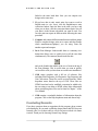
Tutorial Ground Loop Design ResidentialVersion5.1for Windows Powered By: www.gaiageo.com Copyright Notice Ground Loop Design TM Residential Version 5.1 Tutorial © 2008 Celsia, LLC. All Rights Reserved. This guide, as well as the software described in it, is furnished for information purposes only to licensed users of the Ground Loop Design software product and is furnished on an “AS IS” basis without any warranties, whatsoever, express or implied. This may be used or copied only in accordance with the terms of the included EndUser License Agreement. The information in this manual is subject to change without notice, and should not be construed as a commitment by Gaia Geothermal. Gaia Geothermal assumes no responsibility or liability for errors or inaccuracies that may occur in this book. Except as permitted by such license, no part of this publication may be reproduced, stored in a retrieval system, or transmitted in any means, electronic, mechanical, recording, or otherwise, without the prior written consent of Gaia Geothermal. Other brand and product names are trademarks or registered trademarks of the respective holders. Microsoft Excel, Windows, Windows 95, Windows 98, Windows NT, Windows Explorer, Windows ME, Windows 2000, Windows XP, Windows Vista, Trane, and Trane System Analyzer are registered trademarks of Microsoft Corporation and Trane, respectively. Netscape Navigator is a registered trademark of Netscape Corporation. The Ground Loop Design Residential Version 5.1 Tutorial Originally printed in January 2008 Printed in USA Part No. GGENG1006 Visit our Web site at http://www.gaiageo.com. Table of Contents CHAPTER 1 CHAPTER 4 Welcome To GLD 1 Reports and Design Tips 25 New in Version 5.1 1 Reports 25 GLD Features 2 Sharing Project Files 26 Why This Tutorial? 2 Design Tips 27 Concluding Remarks 28 CHAPTER 2 Loads and Pumps 4 Loads Module Intro 4 What Loads Data Does GLD Need? 4 Where Can I Get The Loads Data? 6 How Do I Get the Loads Data Step 1 Step 2 Into GLD? 6 Importing Loads 6 How Do I Choose A Pump? 8 CHAPTER 3 Heat Exchanger Design Step 3 Step 4 14 What Is The Studio Link System? 14 How Do I Start Designing? 15 NOTE: To start designing immediately, begin at STEP 1 and continue through STEP 7. Step 5 and 6 W E L C O M E T O G R O U N D L O O P D E S I G N Chapter 1 Welcome To Ground Loop Design Residential W elcome to Ground Loop Design (GLD) Residential Version 5.1, Gaia Geothermal’s residential ground source heat pump system design software. GLD offers designers a suite of rapid, userfriendly, customizable and accurate design optimization tools. With GLD, designers spend less time designing and more time offering competitive proposals, installing systems, and satisfying customers. GLD works in conjunction with the GeoXergy PlugIn to provide a full set of design tools including loads calculations, energy analysis and cost comparison, cash flow payback, and a greenhouse gas emissions reduction calculator. See the GeoXergy PlugIn documentation for more information. As you progress through this Tutorial in the next 15 minutes, you will create your first design and also will learn how GLD can help you design faster and more effectively. Thank you for your interest in GLD Residential. We think you will enjoy the program. New in Version 5.1 Ground Loop Design Residential Version 5.1 adds a range of features to the program including: · fixed temperature and fixed length design modes in the borehole design module. In fixed temperature mode, designers specify inlet temperatures and the program calculates bore lengths. In fixed length mode, designers specify a loopfield length (borehole length x number of boreholes) and then have the program calculate heating and cooling inlet temperatures 1 W E L C O M E T O G R O U N D L O O P D E S I G N GLD Features FULL POWER 3 Types of Heat Exchangers Loads Inputs Vertical • Horizontal • Surface Water ZonebyZone The Residential version of Ground Loop Design includes three design modules: one for vertical borehole, one for horizontal and one for surface water (pond, lake, etc.) installations. GLD also includes the zone loads module for detailed zonebyzone loads. The loads module can be used to manually or automatically select from hundreds of included watertoair and watertowater heat pumps. The loads data can be shared between modules using Ground Loop Design’s unique linking system. In addition, data from external loads programs (such as the GeoXergy PlugIn) as well as from Excel files can be imported conveniently into the loads modules. COMPLETE CUSTOMIZATION Data Sheets • Reports • Help Files Because of the extensive customization and override features included in the software, Ground Loop Design is suited ideally for both standard and non standard applications (which can involve significant variations in equipment, loads, and operational parameters for each zone in the design). The user, who may prefer to add his or her specific images or data sheets, has the freedom to customize the data reference files. EFFECTIVE COMMUNICATION English Units • Metric Units • Pro Reports • Multilingual With instant, direct metric/English unit conversions and foreign language capabilities, Ground Loop Design is a truly international program. With Ground Loop Design, communicating project parameters, equipment requirements and loads data with coworkers, partners, and vendors anywhere in the world is efficient and easy. Furthermore, after designing a project, it is effortless to email the small project and zone files to colleagues. Why This Tutorial? The primary purpose of this tutorial is to show you how to design quickly and effectively with GLD. To meet this goal, this tutorial will take you stepbystep through the design of a vertical borehole heat exchanger for a midsized residence. 2 W E L C O M E T O G R O U N D L O O P D E S I G N · In chapter 2, you will discover how easy it is to import loads into GLD. Next, you will learn how to match the pumps to the loads using GLD’s automatic and manual pump selection options. · After mastering the loads side of the program, you will look at the heat exchanger side. In Chapter 3 you will design a vertical borehole system for the project using the loads data we import in Chapter 2. You can explore the horizontal design module and surface water module on your own. · In chapter 4, you will learn how to print out professional reports that are as impressive as your designs. The guide concludes with a series of tips that will help you take full advantage of the program. The secondary purpose of this tutorial is to introduce you to some of the more advanced features of the program. A complete description of the program can be found in the full User Manual. The following icons appear throughout the guide: STEP 1 i This icon appears in the left margin of this guide at the beginning of every major step in the design process. If you want to focus your time mainly on learning how to design, just follow these icons stepbystep through the sample design. This icon appears in the left margin when this guide offers more detailed information about GLD See the full user manual for installation and license dongle information. 3 L O A D S A N D P U M P S Chapter 2 Loads And Pumps i G round Loop Design Residential Version 5.1 is designed for residential applications and has a maximum peak load design capacity of 200 kBtu/hr. Systems with peak loads that are greater than 200 kBtu/hr fall into the realm of commercial systems and generally require more advanced heat transfer models that take longterm thermal effects into account. Additionally, larger residential systems oftentimes have internal heat gains and losses (from media rooms, pools, etc), and therefore, loads for such systems should be modeled using more advanced methods to ensure optimal system design. If your peak load is 200 kBtu/hr or greater, consider upgrading to Ground Loop Design Premier Version 5.1, a software suite that provides significantly enhanced capabilities and features. Regardless of the project type, note that the results that GLD calculates are only as good as the information that the designer inputs. It is ultimately the designer’s responsibility to confirm that input values are reasonable. Loads Module Introduction GLD Residential Version 5.1 provides users with the flexible and powerful Zone Manager Loads module. For small installations, the entire loads can be entered into a single zone. For larger installations, designers can take advantage of the more advanced program features by entering loads on a zonebyzone basis, and then matching pumps to loads/zones in an automatic or manual fashion (watertowater and watertoair pumps are both available in the program). i What Loads Data Does GLD Need? Designers need the following data to begin using the program. Note that the more detailed the loads data are, the more accurate the final design will be. 4 L O A D S A N D P U M P S Minimum Loads Data Requirements: · Peak hourly heating and peak hourly cooling loads (in kBtu or kWh) · The Annual Running Time (0100%) Two ways to Calculate the Annual Running Time: 1. Sum the total cooling loads for the year. Divide the sum by the peak hourly cooling load to get a result with units in "hours." Divide the result by the number of hours in a year (8760). The resulting percentage is the annual running time. Example: Total annual cooling kBtus: 18500 kBtu peak: 22 kBtu/hour 18500 kBtu/ 22 kBtu/hour =841 hours 841 hours/8760 hours/year = 9.6% annual running time. Repeat for heating loads 2. For cooling, if the system were running at peak capacity, how many hours would it have to run for in order to take care of the cooling loads for the entire year? After determining the answer, divide it by 8760 to get the annual running time percentage. Repeat for heating loads. GLD uses these loads data both to match pumps to loads and to determine the appropriate length of the heat exchanger. The mathematical models that GLD uses are described in detail in the full User Manual. 5 L O A D S i i A N D P U M P S Where Can I Get The Loads Data? GLD users oftentimes get their loads data from residential loads (heat gain/heat loss) calculation programs such as the GeoXergy PlugIn. These programs often output data into Excel (or are Excel worksheets themselves), and from Excel it is straightforward to copy and paste the data into GLD. This process will be explained below. Remember that GLD outputs good results only when the user inputs good loads data. How Do I Get The Loads Data Into GLD? After calculating or receiving the appropriate loads data, there are two easy ways to get the data into GLD: · GLD can import the loads data from an Excel spreadsheet provided that the loads data follows a prescribed format (more on this below) · GLD can accept input directly into the loads screen text boxes Both of these methods are explained below. For the demonstration project, we will follow the first method. Importing Loads Data From Residential Loads Analysis Programs: the GeoXergy PlugIn Step 1 STEP 1.0 For the demo project, we will import the loads data from the GeoXergy PlugIn. Open up the GLD program. STEP 1.1 Near the top of the program you will see a row of icons. The icon for the Zone Manager Loads module looks like this: Click on the icon. STEP 1.2 The Zone Manager Loads module is now open. It looks like this: 6 L O A D S A N D P U M P S Zone Manager Module With No Open Zone STEP 1.3 Click on the New Zone icon to add one zone to the design. The New Zone icon looks like: and can be found at the top of the module. A new zone with all parameters set to zero is now open. STEP 1.4 We are now ready to import loads data from the GeoXergy PlugIn. The data in the GeoXergy PlugIn should look something like this: Cooling Heating Peak (kBtu) Annual Running Time Highlight the peak and annual running time data in the PlugIn and copy them to the clipboard. Be sure to copy only the data and not the surrounding data descriptions. Confirm that GLD is in the units format (metric/English) that matches your loads data before you import. You can convert between the two formats via this button: 7 L O A D S A N D P U M P S It can be found at the top of the GLD program at the very right end of the row of icons. STEP 2.5 Click the Excel button in the Zone Manager Loads module. It looks like this: The loads data is now in GLD and it should look like this: Zone Manager Loads Module With Imported Data demo continues on page 9 If you will be manually entering the loads data and need more information about the annual running time, click the ? button in the Zone Manager. How Do I Choose A Pump? The Zone Manager Loads module offers three methods for selecting pumps: · Automatic selection based on the active heat pump series · Manual selection from a list of all available pumps 8 L O A D S A N D P U M P S · Custom input of pump data In this tutorial, we will have the program automatically select a heat pump from the active heat pump series. By active heat pump series we mean that the user first selects a heat pump manufacturer and pump family (the active series) and then the program auto selects a pump from the family to match the loads Automatic selection based on the active heat pump series First, select the active heat pump series by clicking on the HEAT PUMPS tabs as seen below: Step 2 STEP 2.0 When you do so, a screen similar to the one below will become visible: Heat Pump Series Selection 9 L O A D S A N D P U M P S In this panel, you can select a manufacturer and heat pump family and view the pumps available in the family. Note that you cannot select individual heat pumps here. This list only indicates which pumps are available for autoselection by the program. If you want to manually select a particular pump, keep reading. In this example, select the: Waterfurnace Premier P series STEP 2.1 Return to the Loads tab and take a look at the heat pump data panel: Prior to Selecting a Heat Pump STEP 2.2 With no pump currently selected, the Custom Pump box is checked, and all pump performance values are at 0.0. To have the program auto select a pump from the Waterfurnace Premier P family, hit the Auto Select button. This is what you will see: Selected Pump Performance Characteristics The program has selected the PO46 pump based on the peak loads that we entered earlier in this tutorial. STEP 2.3 Click on the Details button to see details about the selected PO46 pump 10 L O A D S A N D P U M P S Selected Pump Details This screen displays details about the selected pump. It also displays the load side Entering Air Temperature (EAT) for both cooling and heating. GLD employs an accurate system for modeling heat pump performance. Both source and loads side factors affect heat pump performance and GLD models these factors. Users can modify the EAT as necessary for specific design applications. In this tutorial, the EAT values will not be modified. Click the Return button to go back to the original view: Selected Pump Performance Characteristics Manual selection from a list of all available pumps If an automatically selected heat pump is for any reason undesirable, or a different pump series from the same manufacturer or even from a different manufacturer is required, the Select button may be used. This button allows the designer to choose any of the database pumps. As with the AutoSelect button, all of the associated fields are calculated automatically once the pump is selected. When the Select button is pressed, a selection panel appears. After a pump is chosen, pressing Select Pump will place the pump in the zone 11 L O A D S A N D P U M P S and automatically calculate all of the associated parameters. Cancel will return the user to the main display without changing any pumps. Note: Unlike with AutoSelect, a pump that is manually selected may or may not match the loads in the zone. It is the responsibility of the designer to make sure the pumps match the loads and zones. Custom input of pump data In addition, users can manually override any performance values by simply clicking in the appropriate dialog box and typing in a new value. If you do this, the “custom pump” box will become checked automatically to remind you that you have modified the standard data. Modifying the standard pump data is useful when you intend to use a customized pump. STEP 2.4 Users now have the opportunity to modify system flow rates, unit inlet temperatures and pump performance parameters, Note that when we design the vertical borehole heat exchanger in the next chapter, you will have the opportunity to modify the flow rate and unit inlet temperatures. For the time being, use the following values: · Flow Rate: 3.0 gpm/ton · Cooling Inlet Temp: 85 0 F · Heating Inlet Temp: 50 0 F Note that if you want to use metric units, just click on the English/Metric units conversion button: It can be found at the top of the GLD program at the very right end of the row of icons. STEP 2.5 Now save the loads data. Click on the floppy disk icon at the top of the Zone Manager Loads module. Save the file in Program Files/Gaia Geothermal/Ground Loop Design/Zones as Demo.zon. Summary: We have imported loads data into the Zone Manager Loads module and selected a pump. This is what your Zone Manager Loads module should look like: 12 L O A D S A N D P U M P S Zone Manager Loads Module: Ready for Heat Exchanger Design demo continues on page 14 13 H E A T E X C H A N G E R D E S I G N Chapter 3 Heat Exchanger Design G Round Loop Design includes vertical, horizontal and surface water heat exchanger design modules. As you continue with the vertical heat exchanger design, you will begin to see how the modular nature of GLD offers so much flexibility. Although each module is standalone and independent, the modules communicate and share data with each other via the Studio Link system. What Is the Studio Link System? STEP 3 The best way to describe the Studio Link system is to demonstrate it. Please open a new Vertical Borehole Design module. You can do this by clicking on the Vertical Borehole icon. It is the first icon to be found in the top left corner of GLD and looks like this: STEP 3.0 When you click it, a new window will open in GLD. This is the Vertical Borehole Design window (or module). It looks like this: 14 H E A T E X C H A N G E R D E S I G N New Vertical Borehole Design Module STEP 3.1 We first have to connect the data we entered in the Zone Manager Loads module to the Borehole Design module. The Studio Link system will help us do this. At the top of GLD look for the following two icons: link unlink STEP 3.2 The icon on the left is the link icon and the icon on the right is the unlink icon. Click on the link icon and see what happens. Notice in the bottom left corner of both modules (the Borehole module and the Loads module) that there is a lighted box. It looks like this (the color may vary): This box indicates that the two modules are linked and have bidirectional communication. 15 H E A T STEP 3.3 STEP 3.4 Step 4 E X C H A N G E R D E S I G N Now click the unlink icon. You will notice that the position and color of the light has changed, indicating that the two modules are no longer communicating. It looks like this: Push the link button again to reestablish communications. Now That My Loads Data Are Linked To The Borehole Designer, How Do I Start Designing? The Borehole Design module allows the user to enter various parameters with respect to the desired vertical borehole system using a tabbed series of panels as seen below: Borehole Design Panel List STEP 4.0 STEP 4.1 Click on the Information tab to open the Information panel. Any information you type in this panel will be included in printable reports. In the Information panel, please enter the following data: · project name: Gaia Headquarters · client name: Your Choice · address: Your Choice STEP 4.2 Now click on the Extra kW panel that is directly to the left of the Information Panel. This is what you will see: 16 H E A T E X C H A N G E R D E S I G N Extra kW panel i The entry box, “Circulation Pumps”, is for the energy required by the system circulation pumps. Note: To make a kilowatt entry in the ‘Pump Power’ box, switch to metric units, enter the kilowatt value, and then return to English units. You can do this by clicking on the metric/English units conversion button: This button can be found near the top of the program at the far right end of the row of icons. Pump Power Calculator i Click on the Pump Power Calculator button to open the calculator. It looks like this: 17 H E A T E X C H A N G E R D E S I G N Pump Power Calculator If the pump efficiency, system flow rate and head loss are known, the Pump Power Calculator can be used to determine the pump power. Click on the Close button. STEP 4.3 For this demo, we will input the following values in the Extra kW Panel: · Pump Power: 1hp · Pump Motor Efficiency: 85% STEP 4.4 Now click on the Pattern tab. This is what you will see: Pattern Panel i 18 H E A T E X C H A N G E R D E S I G N Information pertaining to the ground field arrangement is in the Pattern panel. This includes the fixed borehole length design option, the vertical boreholes pattern and the borehole separation. See the full user manual for information about the fixed borehole length design option. Note: The separation between vertical bores value is the centerto center distance between adjacent bores. STEP 4.5 For this demo project, input the following values: · · · · Fixed Length Mode Number of Rows Across: Number of Rows Down: Borehole Separation: Off 1 3 20 ft After we finish our initial design and determine what our total pipe and drilling requirements are, we will be able to modify these input values if necessary. STEP 4.6 Now click on the UTube tab. The screen will look like this: UTube Information i 19 H E A T E X C H A N G E R D E S I G N The UTube panel contains information related to the pipe and bore. The main purpose of the panel is to obtain a value for the borehole thermal resistance. STEP 4.7 In this demo, input the following values: · · · · · STEP 4.8 Pipe Size: Pipe Type: Flow Type: Borehole Diameter: Grout Thermal Conductivity: 1 1/4 in SDR11 Turbulent 5.00 in 0.80 Now click on the Soil tabbed panel. You should see the following screen: Soil Panel i Input parameters relating to the soil are located in the Soil panel, as shown above. These include the average ground temperature and the soil type. See the User Manual for the thermal conductivity and thermal diffusivity values associated with each listed soil type. Since 20 H E A T E X C H A N G E R D E S I G N thermal conductivity has a particularly large effect on the bore length calculations the soil type should be determined with care through in situ tests or comparisons with other projects installed in the local vicinity. In addition, the modeling time period can be modified here. Note: For the modeling time period, ten years is used as a standard length of time for the ground temperature to stabilize, although other time periods may be entered if desired. For more information, click the ? Button on the Soil panel. STEP 4.9 For this demo, input the following values into the Soil panel: · Ground Temperature: · Soil Type: · Prediction Time: STEP 4.10 55 0 F Heavy Soil, Saturated 10 years Now we are ready for the Fluid panel. Please click on the Fluid tab. Your screen will look like this: Fluid Panel The circulating fluid parameters may be entered in the Fluid panel. 21 H E A T E X C H A N G E R D E S I G N Note: The system flow rate per installed ton is included on the Fluid panel. This is the system flow rate per ton of peak load, not installed capacity (This is because it is assumed that all units will not be running at full load simultaneously, even in the peak load condition). Note: GLD is a modular program meaning that the program consists of several modules that work together to assist you with your designs. The fluids panel offers one of the most obvious examples of how the different modules communicate with one another. Take a look at the Zone Manager Loads module once again. Notice that the flow rate and the unit inlet temperatures at the bottom of the Zone Manager Loads Module match those of the Fluids panel. Change the cooling inlet temperature in the Fluids panel to 90 o F. Then, click your mouse pointer anywhere inside the Zone Manager Loads Module. The Zone Manager Loads module cooling inlet temperature automatically updates itself along with the pump performance characteristics. This connectivity saves designers much time. While this feature is a tremendous timesaver, the new calculated equipment capacities can lead to changes in selected equipment so the designer must be aware of the changes. Customized pump values must be manually adjusted. STEP 4.11 For this demo, input the following values into the Fluid panel: · · · · STEP 4.12 Cooling Inlet Temperature: Heating Inlet Temperature: Fluid Type: Freezing Point: 80 o F 40 0 F Propylene Glycol 25 0 F We are now ready to perform our initial calculation. Navigate to the Results panel and click on the Calculate button. Your screen should look something like this: 22 H E A T E X C H A N G E R D E S I G N The Initial Calculation The two columns on the Results panel are for heating and cooling. Although all of the numbers shown are valid and respond to changes, the side with the longer required length is printed in bold type so that it stands out. STEP 4.13 In this demo, the heat exchanger is heating dominated (as expected from the loads data). Notice that there are 3 boreholes (in the Pattern panel we specified a 1 x 3 grid arrangement) and that each borehole is about 246 feet long. We now will quickly optimize the design. In this demo we do not want to drill deeper than 200 feet. Change the grid arrangement on the Pattern tab: · Number of Rows Down: · Number of Rows Down: · Separation Between Boreholes: 23 1 4 20 ft H E A T STEP 4.14 E X C H A N G E R D E S I G N Click on the Calculate button again. The individual borehole length has dropped to about 185 feet. Optimized Design Results demo continues on page 25 Summary: In this chapter, we learned how to link the loads and heat exchanger modules, how to input heat exchanger design parameters and how to optimize a design by modifying parameters. GLD also contains Horizontal and Surface Water Design modules (explained in Chapters 5 and 6 in the User Manual) which you can use in the same way as the Vertical Borehole module. In the next chapter we will show you how to print reports and email project files as well as how to begin taking advantage of some of the more powerful GLD features. 24 R E P O R T S A N D D E S I G N T I P S Chapter 4 Reports And Design Tips W hether you have finished your design and want to send customized reports to vendors, clients and colleagues or need to collaborate on a design with a coworker halfway around the world, GLD offers a variety of communication tools to help you work effectively. In this final chapter, we will show you how to choose and print reports, how to email project files so that colleagues can review, modify or approve designs, and how to take advantage of a few of the many other features that GLD offers. i Step 5 STEP 5.0 Reports At any step in the design process, you can choose to print out a variety of reports including five types of loads/zone reports and one type of heat exchanger report. Zone Reports You should still have the Zone Manager Loads module open. At the top of the module you will see a print icon. Click on it and a dialog box will open that looks like this: Loads Report Choices 25 R E P O R T S A N D D E S I G N T I P S Zone (or loads) reports include only the project information and data from the zones. Five different zone reports exist, containing complete or specific information about the zones. Zone reports are representative of the actual installation rather than the heat exchanger portion of the system. There five different zone report choices include: · Concise Form: Contains important info about loads and operational parameters of equipment · Detailed Form: Contains all info for every zone and a full explanation of the listed parameters · Equipment List: Contains the equipment for each zone. This report is ideal for engineers or contractors who require only equipment details · Loads List: Contains the loads at different times in the day for each zone. · Names List: Contains the full reference names of every zone, the zone number and pump information. This report is useful for when a project has many zones STEP 5.1 Explore the different reports and print one out. Notice that the project information you entered in the Information panel of the Borehole Design module appears in all the reports. Project Reports Step 6 STEP 6.0 STEP 6.1 Now look at the row of icons at the top of the GLD program. Find the print icon and press it (if you cannot click on the print icon, first click the mouse within the Borehole Design module window). You will have the option of printing a Concise Form Choose to print the concise form and take a look at it. Sharing Project Files With Colleagues GLD saves zone files (from the Loads modules) and project files (from the heat exchanger files) separately. Colleagues that use GLD can receive these files as email attachments and view/modify the project designs and/or the loads data. Below is a brief description of the two types of files. 26 R E P O R T S A N D D E S I G N T I P S Zone Files Zone (loads) files are stored as *.zon files in the Ground Loop Design ‘zones’ directory. They have a general format that can be read into any loads module, and they can be used simultaneously in different design modules. Project Files GLD saves project files as *.gld files in the Ground Loop Design ‘work files’ directory. Each project file type (vertical borehole, horizontal, surface water) has a specific format that GLD automatically recognizes. Sharing Files GLD expects to find the files in the following folders: Zone files: Program Files/Gaia Geothermal/Ground Loop Design/Zones Project Files: Program Files/Gaia Geothermal/Ground Loop Design/Work Files When you send or receive files, confirm that the files are in the appropriate directories before trying to open them within the program. Note: GLD is available in foreign languages (contact your distributor for more information). If you are working with clients or coworkers in other countries, you can just email your files to them and they will be able to read the files in their native language. Geoexchange designs can be complex. In our increasingly interconnected world, you can use GLD to minimize the risk of communication problems while working in multiple languages. Design Tips Congratulations! You now know enough about GLD to begin designing worldclass projects with efficiency and ease. Below you will find a list of suggestions for further exploration and design success: 1. After inputting loads and selecting pumps in a loads module, open up two new heat exchanger design modules. Click on one design module to activate it and then click on the link button. Then, click on the other design module to activate it and once again click on the link button. Now, both design modules are 27 R E P O R T S A N D D E S I G N T I P S linked to the same loads data. Now you can compare two designs at the same time. 2. If you have data in only metric units, but want to work in English units (or vice versa), click the English/metric units conversion button. Enter the data in the units you have and when you are done, click the conversion button again. Now all your data is in the format with which you want to work. You can also print out reports in different units following the same procedure. 3. Compare and contrast different manufacturers and heat pumps. Finish a complete design, print out a report, and then change which manufacturer(s)/pump(s) you are using. Print out another report and compare. 4. In the Zone Manager Loads module there is a summary view button that allows users to quickly look at all the zone data simultaneously. The summary button looks like this: and can be found in the middle of the row of icons at the top of the Zone Manager. This is useful when you want to quickly review all the work you have done on a multizone installation. 5. GLD comes complete with a full set of reference files including Fluid Properties, Soil Properties, Pipe Properties and Unit Conversions. These files can be accessed from the Tables dropdown menu found at the top of GLD. These files are HTMLbased and can be modified, customized or added to by the user using a text editor or HTML editor. More information about customizing these files can be found in Chapter 7 of the User Manual. 6. GLD contains a searchable database of information about the program. Click on the Help dropdown menu and choose help. Concluding Remarks If you have questions about or suggestions for the program, please contact your distributor. Do you need a particular design feature that GLD does not currently offer? Let us know and we will do our best to include it in future versions. Thank you for choosing Ground Loop Design. 28