1
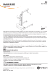
MultiLift550
1
2
Manual - English
3
4
5
6
7
8
9
10
11
12
13
14
15
16
REVISION HISTORY
SystemRoMedic
A
A
TM
REV.
DESCRIPTION
DATE
APPROVED
B
B
C
C
D
D
E
E
F
F
G
G
H
H
J
J
Safe working load:
250 kg/550 lbs
K
K
MultiLift550 is a motor-driven patient lift controlled by a steering handle. It is driven by two powerful rear wheels with inteNAME
L
DRAWN
hc-mabr
DATE
2011-07-14
APPROVED BY
grated electric geared motors and can be moved over carpets, electric leads and other small obstacles. The rear wheels
STATUS:
TITLE
COMMENTS:
Unless otherwise stated, general
tolerances according to ISO 2768-m
SIZE
DWG. NO.
REV.
A1
can be turned, meaning that the lift can be moved sideways or rotate on its own axis and be placed exactly as required.
MATERIAL:
M
SCALE:1:4
WEIGHT:
g
The vertical lifting function gives great freedom to handle the patient, because the lifting strap can be moved freely in any
1
2
3
4
5
6
7
8
9
10
11
12
This drawing and any information or descriptive matter set out hereon are the confidential and copyright property of Handicare
and must not be disclosed, loaned, copied or used for manufacturing, tendering or any other purpose without their written permission.
direction with the sling bar. The extra long lifting strap makes it possible to handle a patient direct from the floor.
MultiLift550 can be used for several different types of patient handling without the need of wheel chair or toilet chair. It
can be used for lifting a patient in a seated or supine position as well as gait training.
Handicare’s SystemRoMedic product series includes a range of lifts, slings and other accessories. SystemRoMedic
adopts a holistic approach to patient transfers and is organized in four categories: transfer, positioning, support and
lifting.
Functional inspection
Visual inspection
Inspect lift functions regularly. Check to ensure that material is free from damage.
Before use:
Ensure that the product is correctly assembled.
Check slingbar connection and safety latch function.
Check lift and base-width movement.
Check to ensure that the actuator is correctly installed.
Always read the manual
Always read the manuals for all assistive devices used during a transfer.
Keep the manual where it is accessible to users of the product.
The lift may only be used by persons who have received instruction in the operation of the lift.
Manual nr: 00741-En Ver. 1 111017
SHEET 1 OF 1
Table of contents
Table of contents........................................................................... 2
Safety instructions.......................................................................... 3
Product description........................................................................ 4
Safety Check before use................................................................. 5
Care and maintenance.................................................................... 6
Technical data.............................................................................7-8
Product description........................................................................ 9
Specification................................................................................ 10
Operation..................................................................................... 11
General functions.................................................................... 11-12
Driving function....................................................................... 13-14
Lifting function.............................................................................. 15
Electronic weighing and control function........................................ 16
Adjusting of the steering handle bar consol................................... 16
Emergency lowering..................................................................... 17
Charging of the battery................................................................. 17
Battery Pack change/replace........................................................ 18
Transport and storage.................................................................. 18
Accessories................................................................................. 19
Troubleshooting........................................................................... 19
Fault messages in the display....................................................... 20
General suggestions..................................................................... 21
Contact information...................................................................... 22
This Instruction contains important information for the user of the lift. Everybody that uses the lift must read and understand the content of this Instruction. The Instruction must always be available to the users.
2
M A N U A L SystemRoMedic
TM
Safety instructions
CAUTION!
Read the instruction guide carefully before using MultiLift550.
Lifting and handling of a person always include a risk and it is therefore very important that the content of this instruction
is understood fully and complete. Only personnel that are fully informed should use the lift.
Contact the local Handicare office if there are any open or unanswered questions.
MultiLift550 is different from an ordinary lift, since it is driven by rear wheels with a build-in electric motor and gear box.
This means the lift drives forward and backwards or moves sideways, when the steering handle is activated. Only a
minimum of exertion is needed.
MultiLift550 must only run on a levelled floor.
There is a risk that the lift tilts, if the foundation or the floor slopes more than 10° degrees forwards or backwards, or
more that 5° degrees sideways.
There is a risk of jamming at the turning point of the legs.
There is a risk of jamming between the legs and wheels, when the lift is moved.
There is a risk of jamming between the sling bar and the lifting sling, when the sling bar is moved.
There is a risk of jamming between the front part of the legs and foot list, bed and door rail, when the lift drives forward.
There is a risk of jamming between the rear cover and foot list, bed or door rail, when the lift drives backwards.
There is a risk of jamming between the cover side and the foot list, bed or door rail, when the lift moves sideways.
SystemRoMedic M A N U A L
TM
3
Product description
MultiLift550 is a motor-driven patient lift with 4 main functions:
•
Movement with self-driving electrical wheels
•
Vertical lifting with free moving sling bar
•
Remote control of lifting function
•
Built-in electronic weighing and control system
MultiLift550 is a motor-driven patient lift controlled by a steering handle. It is driven by two powerful rear wheels with integrated electric geared motors and can be moved over carpets, electric leads and other small obstacles. The rear wheels
can be turned, meaning that the lift can be moved sideways or rotate on its own axis and be placed exactly as required.
The vertical lifting function gives great freedom to handle the patient, because the lifting strap can be moved freely in any
direction with the sling bar. The extra long lifting strap makes it possible to handle a patient direct from the floor.
The control of the lift is remotely via a remote control, but it can also be done directly from the control panel on the lift
overruling the remote control.
MultiLift550 has an electronic, built-in weighing and control system.
MultiLift550 can be used for several different types of patient handling without the need of wheel chair or toilet chair. It
can be used for lifting a patient in a seated or supine position as well as gait training.
The motor driven system secures the aid personnel against working injuries because the lift takes over and does the
hard work for the personnel.
This function is particularly important when handling heavy patients and in the same connection the spreading of the
legs, is designed so that the lift can handle an oversized wheel chair.
The lifting arm is designed with an inlet stub, where the upper part of the sling bar is pulled into a fixed position, so the
patient doesn´t feel an unpleasant movement during transportation.
The lift can be moved with minimum of force, so it is possible to move the patient directly from the bed to the toilet and
back again without intermediate stops. The handling process is reduced to the benefit for both patient and aid personnel. This also reduces the need for extra personal during handling giving economical savings.
CAUTION! Indicates that special precaution has to be taken into consideration.
4
M A N U A L SystemRoMedic
TM
Safety Check before use
As the lift is driven electrically and thereby motor-driven, special precaution must be taken during operation of the lift. When the steering handle is activated, the lift moves and as the motors in the wheels are very powerful, harm to persons and equipment could take place.
Never leave a patient without attention during the handling process.
Before use:
•
Read the Instruction Guide before using the lift
•
Make certain that the user is fully informed about the operation of the lift
•
Make certain the lifting slings, the sling bar and other accessories matches the patients needs.
Before lifting and handling is started:
•
Make sure the battery pack is fully charged.
•
Check the lift for outer damages.
•
Check that the sling bar is fastened correctly to the lifting strap.
•
Check that the lifting strap is not worn and can be moved freely into the inlet stub on the lifting arm.
•
Check that the lifting strap is not twisted.
•
Check the steering handle, leg spreading and the remote control.
•
Check that the accessories are fully intact.
•
Check that the lifting sling is correctly and safely placed onto the patient, so that no harm can take place.
•
Check that the sling is correctly mounted onto the sling bar with the sling straps in tightened position before the patient is lifted up from the bed.
If an unintentional situation occurs during the lifting and the handling, pres the emergency stop –the red button – placed
on the cover at the button right behind the lifting mast.
SystemRoMedic M A N U A L
TM
5
Care and maintenance
Repair and maintenance must only be carried out by personnel approved by Handicare AB.
MultiLift550 must be kept in a room with normal room temperature and moisture conditions. If it is kept cold and moist,
motors, electronics and other mechanical parts may be harmed.
Make sure that the battery pack is charged regularly – optimum every night – to have maximum power in the batteries.
Clean the lift as required without use of phenol or chlorine-containing, as this may harm the aluminium and the polyamide
material (cover). White spirit may be used.
The lifting strap must only be cleaned with water. Use a hard wringed wet cloth and let the strap dry before use.
MultiLift550 should be kept clean at all times.
During transportation and when the lift is not in use for a longer time, the emergency stop should be activated.
Inspection and control should be carried out once a year by Handicare AB approved personnel.
6
M A N U A L SystemRoMedic
TM
Technical data
MultiLift550 is designed and manufactured according to the global standard ISO 10535. It is CE marked according to EU
legislation. It is EMC tested and approved.
Radio transmitting equipment, cellular phones, etc. shall not be used in the close proximity of the device, since this could
influence the performance of the device.
Particular precaution must be considered during use of strong emission sources such as High Frequency surgical equipment and similar, e.g. the HF-cables are not routed on or near the device. In case of doubt, contact a qualified technician
or your local representative.
Max load: 550 Ibs/250 kg
If the lift is loaded by more than stipulated max. load, the lifting function is blocked.
MultiLift550 is tested by an accredited testing institute and complies with the requirements of the directives for medicaltechnical Class 1 products (MDD 93/42/EEC).
Battery pack:
24 volt 15 Ah LiFePO4, maintenance free and rechargeable
Battery (Remote): Lithium Button Cell, CR2450, 3V 550 mAh
Charger:
LiFePO4 24V (29.2 volt 2 A)
(100-240VAC 50-60Hz Class I)
Charging time:
2-10 hours
Wheels:
Front: 3.93 inch twin wheels (100 mm)
Rear: 8.35 inch with build-in motor, gearbox and EMB brake (210 mm)
Materiel:
Aluminium /Steel / ABS plastic
Electronic weighing and control system:
Measuring range: 44 to 550 lbs (20 to 250 kg)
Resolution: 1 lb (0,5 kg)
SystemRoMedic M A N U A L
TM
7
Technical data
Emergency lowering:
Mechanical and electrical
Protection/ Noise level: IPX4 / 60 dB(A) (unloaded/loaded)
Temperature range:
50-95 °F (10-35 °C)
Moisture:
30-70 %
Intermittent run: 15/85 % (max 2 min cont. - rest 18 min)
Operation force:
Buttons 5 N, Driving 50 N, Break 60 N
Expected Life time:
10 years, Batteries 2000 chargings or 5 years
Number of lifting:
200 lifting with full load (lifting only)
Travelling distance:
10 km with full load (travelling only)
Weight:
Complete 215 lbs (98 kg)– unit 202 lbs (92 kg), battery pack 13 lbs (6 kg)
This lift is made for indoor use
Type B protection against electric shock
Class I equipment
Follow instruction for use
Special precaution has to be taken into consideration.
PATENT: US7,634,824 BZ and PATENTS PENDING
8
M A N U A L SystemRoMedic
TM
2
Product description
3
4
5
6
7
8
9
10
11
2
1
3
4
5
18
17
15
16
14
6
13
12
10
6
11
9
8
2
7
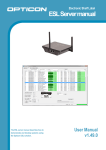
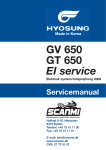
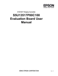
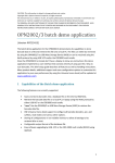
1. Lifting arm
10.
Emergency stop
2. Collision safety sensor
11. Emergency lowering
3.
Inlet stub with finger protection
12. Charger plug
4.
Lifting strap
13.
Battery pack
5.
Sling bar
14.
Lifting mast
6.
Front castor
15.
Steering handle
7.
Wheel break
16.
Handlebar
8.
Power wheel with EMB break
17.
Remote control
9.
Cover
18.
Electronic weighing system and info display
3
4
SystemRoMedic M A N U A L
TM
5
6
7
8
9
10
11
9
Specification
PDF created with pdfFactory trial version www.pdffactory.com
Working load
US standard
Metric
Units
11 - 550
5 - 250
Ibs / kg
Lifting speed, strap
1.26 – 1.85
32 – 47
inch/s / mm/s
Weight of the unit with
215
98
lbs / kg
Driving speed
1.4
2,3
mph / km/h
Turning diameter
54.7
139
Inch / cm
Intermittent
15/85 % (cont. max 2 min/18 min)
Emergency stop
Yes
Emergency lowering
Electrical & mechanical
battery
10
M A N U A L SystemRoMedic
TM
Operation
The operation can be separated into 4 functions:
•
General function
•
Driving function
•
Lifting function
•
Weighing and control function
The operation of these functions will be described separately.
General functions
Switch on MultiLift550
MultiLift550 can be turned on or off by pushing the “on”-button. When
the lift is turned on the display will light up and the LEDs for driving
function will light up, to show the state of the driving function.
Normal or training/positioning operation
Normal or slow speed can be chosen by activating this button.
The lift moves as standard at normal speed.
By activating the button, the speed will be approx. ½ of normal speed,
which makes it possible to place the lift exactly as wanted. It can also
be used during training; leg spread function and the turning of the
wheels are not affected by the ½ speed function. When selecting the
training/positioning speed the yellow light is on.
It is possible to change speed by pressing the button again.
Battery Condition
MultiLift550 will give 3 quick short beeps, when the battery needs to
be charged, hereafter there is only power on the battery to make 1
more full lift.
1
2
3
4
5
6
7
8
9
10
11
12
13
It is time to recharge the battery pack before using it again.
14
15
16
REVISION HISTORY
A
A
DESCRIPTION
REV.
DATE
APPROVED
B
B
Emergency stop
C
C
D
The emergency stop is placed on top of the cover right behind the
E
lifting mast and can be activated by pushing the RED button. All func-
D
E
tions will be deactivated and the lift cannot move.
F
F
Resetting is made by lifting up the activation plate and push hard on
G
G
“1” on the rocker button. Two small “clicks” will be heard.
H
H
J
J
K
K
NAME
L
DRAWN
hc-mabr
DATE
2011-07-14
APPROVED BY
STATUS:
TITLE
COMMENTS:
Unless otherwise stated, general
tolerances according to ISO 2768-m
SIZE
DWG. NO.
REV.
A1
MATERIAL:
M
SCALE:1:1
1
2
3
4
5
6
7
8
SystemRoMedic M A N U A L
TM
9
10
11
12
WEIGHT:
g
SHEET 1 OF 1
This drawing and any information or descriptive matter set out hereon are the confidential and copyright property of Handicare
and must not be disclosed, loaned, copied or used for manufacturing, tendering or any other purpose without their written permission.
11
Tilt-sensor system
MultiLift550 is equipped with a tilt-sensor, which is activated, if the lift is
tilted backwards about 10°.
The driving system is blocked, so the lift cannot move. By pressing
the “0” button placed under the display, the tilt-sensor is deactivated
during a period of 5 seconds and the lift can now be pulled backwards. If the lift is not pulled backwards during the 5 second period the
tilt-sensor will be activated again and the lift cannot be moved. Repeat
the pressing of the “0” button to deactivate the tilt-sensor.
The tilt warning is shown on the display followed by the needed action.
Due to the risk of injury, never use your hands to lock the foot brake!
Brake – locking the rear wheels
MultiLift550 has a mechanical brake. It can be activated with the brake
pawls on the rear wheels by pressing it down.
The brake is an EMB brake system (Electro Mechanical Brake) meaning that it automatically unlocks the wheels, when MultiLift550 is turned
on and handled by the steering handle. In all other cases the wheels
are locked and prevent the lift to move.
The locked wheels can be permanent unlocked again by lifting the
brake pawl.
DRAWN
APPROVED BY
STATUS:
COMMENTS:
Unless other
tolerances a
4
5
12
6
7
8
9
10
11
This drawing and any info
and must not be disclosed
12
M A N U A L SystemRoMedic
TM
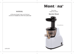
Driving function
Driving the lift takes place via the steering handle, which is part of the intuitive
control system.
5(9,6,21+,6725<
$
$
5(9
'(6&5,37,21
'$7(
$33529('
%
%
The steering handle is controlled by a light pressure with the hands in the wanted
&
&
direction. This creates a good contact to the lift, the movement feels natural and
'
'
it is easy to drive with the hands on the steering handle.
(
(
By pushing the steering handle forward the lift moves forward.
)
)
*
*
+
+
When transporting a patient, the sling bar should be placed into the inlet stub at
-
-
the lifting arm. Thereby the sling bar is locked onto the inlet stub, which means
.
.
that the patient does not feel unpleasant swinging caused by a free hanging
1$0(
/
'5$:1
KFPDEU
'$7(
$33529('%<
lifting strap.
67$786
7,7/(
&200(176
8QOHVVRWKHUZLVHVWDWHGJHQHUDO
WROHUDQFHVDFFRUGLQJWR,62P
6,=(
':*12
5(9
$
0$7(5,$/
0
6&$/(
:(,*+7
J
6+((72)
7KLVGUDZLQJDQGDQ\LQIRUPDWLRQRUGHVFULSWLYHPDWWHUVHWRXWKHUHRQDUHWKHFRQILGHQWLDODQGFRS\ULJKWSURSHUW\RI+DQGLFDUH
DQGPXVWQRWEHGLVFORVHGORDQHGFRSLHGRUXVHGIRUPDQXIDFWXULQJWHQGHULQJRUDQ\RWKHUSXUSRVHZLWKRXWWKHLUZULWWHQSHUPLVVLRQ
There is a short ”death time” from activating the steering handle until the lift starts
moving.
This is a safety precaution to avoid that the lift will move in case the steering
handle is touched unintentionally.
When the steering handle is released, it goes back into neutral position and the
lift stops.
Be aware that the lift is motor-driven and therefore continues moving as long as the steering handle is activated.
The motors in the rear wheels are so powerful, that it is possible to overturn things, a foot or a door-rail, etc., if
one is not very careful.
Driving the Lift
MultiLift550 has three different driving modes:
- Normal driving
- Driving sideways
- Rotate on its axis
This can be chosen by the 3 buttons on the handlebar consol. Above each
button a light indicator shows, which driving function has been chosen. By
pressing the button the wanted driving function is indicated by a green light.
The button must be pressed until the green light is turned on. If the light
shows red the function has not been finalized and the lift will not move.
All the buttons are “Hold to Run”, therefore the buttons should be hold down until
the LED turn to green.
SystemRoMedic M A N U A L
TM
13
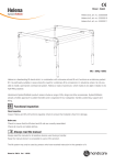
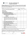
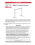
Normal position – straight driving.
The lift drives straight forward and runs via the rear wheels. By tilting the steering handle
forward or backwards, the lift drives straight forward or backward or tilting to the side for
turning. By twisting the steering handle forward and at the side at the same time, the lift
will move forward and turn.
If you want a quick stop, the steering handle can be pulled the opposite direction shortly,
-the lift will stop rapidly.
Note: This must only be done in a short instance because the lift may start moving backwards.
Sideways driving.
In this position the rear wheels are turned 90° to the direction of travel. The lift will drive
sideways in this position by pulling the steering handle at the side you want the lift to
move. Tilting forwards or backwards on the steering handle gives no movement in this
position.
Driving in a circle.
In this position, the rear back wheels are sloped - approx. 45° - so that the lift turns
around its own axis. The lift can be turned in a very small circle in this position. Tilt the
steering handle against the side you want the rear end of the lift to turn. Tilting forward or
backward does not give any movement.
Spreading of legs
The legs can be spread or closed by the buttons on the handlebar consol.
Push the button and hold it until the wanted movement has been finished. This operation
stops when the maximum position has been reached - closed or open.
Legs closing.
Legs spreading
14
M A N U A L SystemRoMedic
TM
Lifting function
The lifting functions are controlled by the remote control; independent of whether
the remote control is placed on the lift or in the hand.
There is a control panel on the lift, where the remote control must be placed. This
control panel can also be used and has first priority above the remote control.
The remote control is made by an infrared system and the control must be
pointed against one of the four sensors placed on the upper part of the lifting
arm, on the back of the lifting mast or on either side of the handle bar consol.
Lifting arm up or down.
By pressing the “Arrow Up” the lifting arm moves upwards until maximum position has been reached or until pressing the arrow is stopped.
By pressing the “Arrow Down” the lifting arm moves downwards until minimum
position has been reached or until pressing the arrow is stopped.
The sling bar stays in an unchanged position independent of the lifting arm being
raised or lowered.
Sling bar up or down.
By pressing the “Arrow Up” the sling bar will be raised until the button is released
or until the sling bar meets the lifting arm inlet. There is a finger jamming safety
system on the inlet.
Note: Be aware of keeping the strap tight at all times to avoid the strap twisting.
Lifting arm and sling bar up and down.
This function raises and lowers both the lifting arm and the sling bar at the same
time. Pushing “Arrow Up” the sling bar will be raised until it reaches the lifting
arm, then both the sling bar and the lifting arm raise until the button is released
or the lifting arm reaches its max. lifting height.
Pushing the “Arrow Down” moves the lifting arm down until it reaches the sling
bar and they both move down to the lifting arm’s lowest point, hereafter the sling
bar continues to move down as long as the down button is pushed.
NOTE: If the remote control has been removed from the lift, the functions can be
operated directly from the lift control panel.
SystemRoMedic M A N U A L
TM
15
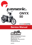
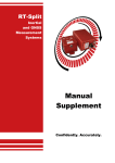
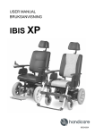
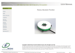
Electronic weighing and control function
The lifting strap must be visible, i.e. hang freely from the inlet nozzle of the lifting
arm. See the top photo, showing appLoad - - - - .
The built-in electronic weighing system shows the weight on the lifting strap,
when the strap is visible – bottom photo.
“Zeroing” can be made by pressing the “0” button.
4
5
6
7
1
8
2
9
3
10
4
11
5
12
6
7
13
8
14
9
15
1
2
10
16
11
3
4
12
5
13
6
14
7
15
8
16
9
REVISION HISTORY
REVISION HISTORY
A
10
11
A
DESCRIPTION
DATE
REV.
APPROVED
B
12
13
14
RE
A
A
REV.
DESCRIPTION
DATE
APPROVED
REV.
DESCRIPTIO
B
B
B
Adjusting of the steering handle bar consol
C
C
C
C
D
D
D
D
E
E
E
E
F
F
F
F
G
G
G
G
H
H
H
H
J
J
J
J
K
K
K
K
The handlebar including the steering handle can be adjusted manually up or down depending on the height of the operaNAME
L
DRAWN
L
NAME
DATE
hc-mabr
DATE
STATUS:
TITLE
TITLE
DWG. NO.
SIZE
Unless otherwise stated, general
tolerances according to ISO 2768-m
REV.
DRAWN
hc-mabr
DATE
2011-0
APPROVED BY
STATUS:
COMMENTS:
Unless otherwise stated, general
tolerances according to ISO 2768-m
NAME
2011-07-14
APPROVED BY
STATUS:
tor, to ensure the correct ergonomic position.
hc-mabr
DRAWN
2011-07-14
APPROVED BY
COMMENTS:
A1
SIZE
DWG. NO.
COMMENTS:
REV.
Unless otherwise stated, general
tolerances according to ISO 2768
A1
MATERIAL:
MATERIAL:
M
M
4
5
6
7
1
8
2
9
3
10
4
11
5
12
6
SCALE:1:1
8
7
WEIGHT:
g
1
2
SCALE:1:1
SHEET 1 OF 1
9
This drawing and any information or descriptive matter set out hereon are the confidential and copyright property of Handicare
and must not be disclosed, loaned, copied or used for manufacturing, tendering or any other purpose without their written permission.
10
3
11
4
g
WEIGHT:
SHEET 1 OF 1
This drawing and any information or descriptive matter set out hereon are the confidential and copyright property of Handicare
and must not be disclosed, loaned, copied or used for manufacturing, tendering or any other purpose without their written permission.
12
5
6
7
8
9
10
11
This drawing and any information or descriptive matter set out hereo
and must not be disclosed, loaned, copied or used for manufacturin
12
This is done by activating the locker mechanism placed on the right hand side of the consol.
The locker slides on the right-hand side of the handlebar can be released by pulling it out and upwards. The handlebar
can hereafter be slid up or down to the wished position.
Lock the handlebar into the wanted position by pushing the locker downwards and in again. Make sure that the locker is
properly locked, before operating the steering handle.
16
M A N U A L SystemRoMedic
TM
Emergency lowering
Electrical emergency lowering can be used independent of any sensor fault. If electrical emergency lowering is
not possible, manual lowering has to be performed.
5(9,6,21+,6725<
$
5(9
'(6&5,37,21
'$7(
$33529('
There is both an electrical and a mechanical emergency lowering system.
%
&
The electrical emergency lowering is located at the right hand side, just below
the fixture for the battery pack. It is activated by applying a thin - less than 2
'
mm - screwdriver or clip onto the contact and pressing it in. The emergency
(
lowering will start after 7 sec. and stop, when the contact is released.
)
*
The lifting strap and the sling bar are now moving downwards.
+
-
5(9,6,21+,6725<
$
$
5(9
'(6&5,37,21
'$7(
$33529('
The mechanical emergency lowering is located at the left hand side of the
.
%
%
cover. After removing the cork, the mechanical emergency lowering can be
1$0(
'$7(
KFPDEU
'5$:1
$33529('%<
&
&
67$786
7,7/(
&200(176
8QOHVVRWKHUZLVHVWDWHGJHQHUDO
WROHUDQFHVDFFRUGLQJWR,62P
6,=(
'
5(9
$
0$7(5,$/
6&$/(
':*12
activated by pushing the hand wheel into the hole.
'
:(,*+7
J
6+((72)
7KLVGUDZLQJDQGDQ\LQIRUPDWLRQRUGHVFULSWLYHPDWWHUVHWRXWKHUHRQDUHWKHFRQILGHQWLDODQGFRS\ULJKWSURSHUW\RI+DQGLFDUH
DQGPXVWQRWEHGLVFORVHGORDQHGFRSLHGRUXVHGIRUPDQXIDFWXULQJWHQGHULQJRUDQ\RWKHUSXUSRVHZLWKRXWWKHLUZULWWHQSHUPLVVLRQ
(
(
)
)
To lower the sling bar, turn the hand wheel clockwise.
*
*
NOTE: 25 turns will lower the sling bar approx. 1 inch (2,5 cm).
+
+
-
-
.
.
1$0(
/
'5$:1
KFPDEU
'$7(
$33529('%<
67$786
7,7/(
&200(176
8QOHVVRWKHUZLVHVWDWHGJHQHUDO
WROHUDQFHVDFFRUGLQJWR,62P
6,=(
':*12
5(9
$
0$7(5,$/
0
6&$/(
:(,*+7
J
6+((72)
7KLVGUDZLQJDQGDQ\LQIRUPDWLRQRUGHVFULSWLYHPDWWHUVHWRXWKHUHRQDUHWKHFRQILGHQWLDODQGFRS\ULJKWSURSHUW\RI+DQGLFDUH
DQGPXVWQRWEHGLVFORVHGORDQHGFRSLHGRUXVHGIRUPDQXIDFWXULQJWHQGHULQJRUDQ\RWKHUSXUSRVHZLWKRXWWKHLUZULWWHQSHUPLVVLRQ
Charging of the battery
Charging must not take place, when a patient is in the lift. Make sure that the connection to the charger has
been removed before activating the steering handle.
5(9
5(9,6,21+,6725<
$
'(6&5,37,21
'$7(
$33529('
%
Charging is made by connecting the supplied charger. The socket is placed on
the right-hand side of the battery pack. Connect the charger to the mains and
&
place the small charging plug into the socket on the battery pack. The charger
will show green, when the battery is fully charged.
'
When charging is in progress, MultiLift550 cannot move nor be operated.
(
MultiLift550 cannot be operated as long as the charging plug is inserted. When
)
the lift is switched on, it will show the status of the battery pack on the display,
and be blocked for operation. Remove the charging plug and it is ready for use.
*
SystemRoMedic M A N U A L
+
TM
-
17
3
4
5
6
7
8
1
9
2
10
3
11
4
5
12
6
13
7
8
REV.
A
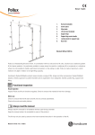
Battery Pack change/replace
Changing the battery pack can be done fast and easily.
B
Turn off MultiLift550.
Remove:
C
D
E
1
2
3
4
5
2
6
3
7
4
8
5
9
6
10
7
11
8
12
13
A
F
REV.
•
Lift up the handle on the battery pack.
•
Push the two holding panels together.
•
Use the handle to lift and remove the battery pack.
D
B
G
C
Replace:
H
D
J
E
K
F
L
•
Hold the battery pack in the handle and use the other hand to guide the battery pack over the plug and in line with the lifting mast.
•
Lower the battery pack onto the power connector.
•
Push down the handle and the two panels will automatically lock the battery pack.
G
DRAW
M
APPR
1
STATU
2
3
4
5
6
7
8
COMM
Unle
tole
H
MultiLift550 can hereafter be switched on again.
3
4
5
6
7
8
9
10
11
This draw
and mus
12
J
Transport and storage
K
If the lift is not to be used for some time or e.g., during transport, we recommend that the emergency stop button be
pressed in.
L
Store the lift at a temperature above freezing point and not exceeding normal relative humidity (about 60%).
NAME
hc-mabr
DRAWN
APPROVED BY
STATUS:
COMMENTS:
Unless otherwise stated,
tolerances according to
M
18
2
M A N U A L SystemRoMedic
TM
1
3
4
5
6
2
7
3
8
4
9
5
10
6
11
7
12
8
This drawing and any information or descriptive ma
and must not be disclosed, loaned, copied or used
Accessories
•
Battery pack, LiFePO4, 24V 15Ah
•
Charger, LiFePO4, 24V (29.2V) 2A Class I
•
Remote 550
•
SlingBar, Small
•
SlingBar, Medium
•
SlingBar, Large
•
Lifting slings: A wide variety of functional and comfortable high quality lifting slings adapted to meet the
different requirements of all kinds of lifting situations and users are available in four different materials and in sizes ranging from XXS to XXL. All models are safe and very easy to use.
Troubleshooting
Symptom
Check
Action
The lift cannot be switched on
That the emergency stop is not
Reset the emergency stop
activated
The lift will not move
If the charger plug is inserted
Remove the charger plug from the
battery pack
The battery does not charge
The battery does not charge
The lift stops during the lifting
That the charger is connected to
Connect the charger and check that
mains
the light turns on
That the connection is correctly
Press the connection into the socket
placed into the socket
until you hear a small ”click”
That no safety sensors have been
Switch off and restart
activated
The lift will not lift the patient
For overload
Switch off and restart
Strange noises or other unusual
STOP immediately and lower the
behaviour
patient.
Contact Handicare
The strap shows sign of damage
STOP immediately and lower the
patient.
Contact Handicare
SystemRoMedic M A N U A L
TM
19
Fault messages in the display
Message
Possibly fault
Possibly solution
Finger Clamp Act
The finger protection on the lifting
Remove the finger or the object that
arm is activated. Something is push-
pushes the finger squeeze
ing the finger squeeze up
Loose Strap
Com error on LC
The sling is on the floor/bed or
Drive the sling up or remove the
something is blocking the sling to
object that blocks the sling to move
move freely
it freely
A fault is detected on the electronic
Try to restart MultiLift550.
scale system
Battery low
The battery pack has not been
Charge the battery pack
charged
Temperature high
A motor has become overheated
Switch off MultiLift550 and let it cool
for some minutes before switching
it on again
Strapmotor Error
A fault is detected on the lifting
Check if the lift is overloaded – re-
controller – could be different causes,
move some load.
e.g. overheating or overload
If overheated - switch of MultiLift550
and let it cool for some minutes and
try again
Battery charge
The charger plug on the battery pack
Remove the charger plug from
is plugged in.
MultiLift550. Remember to replug
The battery is being charged
the charger to full charge the battery
pack after use
NOTE: If a fault still appears then call for technical assistance at Handicare
20
M A N U A L SystemRoMedic
TM
General suggestions
•
Brake fast – If you want a quick stop the steering handle can shortly be placed in the opposite position, i.e. if you drive forward pull the steering handle back ways. Only shortly to avoid the lift moving backwards
•
Drive backwards over larger obstacles (e.g. doorstep)
•
Practice handling of MultiLift550 using a colleague as patient – test person – to become familiar with
operating the lift
•
Use the ”switch on/off” button instead of emergency stop button
•
Charge the battery pack, whenever possible.
SystemRoMedic M A N U A L
TM
21
22
M A N U A L SystemRoMedic
TM
SystemRoMedic M A N U A L
TM
23
SystemRoMedic
TM
For 25 years we have applied ourselves wholeheartedly to developing smart and easy-to-use assistive devices for easy
transfers and to making life and work easier for both patients and personnel in the care sector.
Experience, innovation and training are the basis for SystemRoMedic, a total solution for every imaginable transfer
situation.
Transfer: products for moving patients between locations.
Positioning: products for repositioning in the same location.
Support: products that provide mobility support.
Lifting: products adapted for lifting.
The philosophy behind SystemRoMedic is to prevent occupational injuries while improving the patient’s sense of independence and dignity. Through a combination of training and a complete range of transfer-assistive devices,
SystemRoMedic offers the means to improving both the work environment and the quality of care while enabling
significant cost savings.
Our mission, to help people, has always been, and will continue to be, the driving force of innovation. We love easy
transfers.
Contact your local distributor if you have any questions about the product and its use. See www.handicare.com for a
complete list of distributors. Always make sure that you have the right version of the manual. The most recent editions of
manuals are available for downloading from our website, www.handicare.com
Contact information
Producer:
HeCare
Holtvej 4
DK-6470 Sydals
Denmark
E-mail: [email protected]
CVR: 27492754
Hot line: Contact your local Handicare
representative.
Distributor:
Handicare AB
Veddestav. 15, box 640
SE-175 27 Järfälla
SWEDEN
Tel: +46 (0)8-557 62 200
Fax:+46 (0)8-557 62 299
E-mail: [email protected]
Internet: www.handicare.com