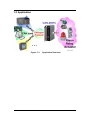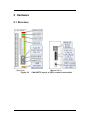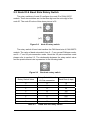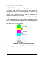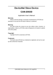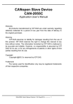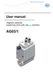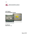
1
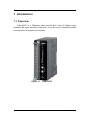
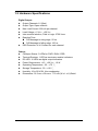
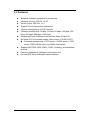
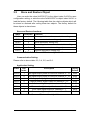
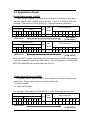
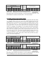
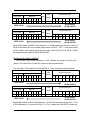
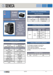
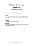
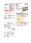
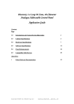
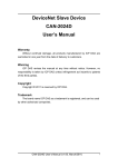
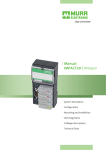
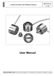
CANopen Slave Device CAN-2057C Application User’s Manual Warranty Without contrived damage, all products manufactured by ICP DAS are warranted in one year from the date of delivery to customers. Warning ICP DAS revises the manual at any time without notice. However, no responsibility is taken by ICP DAS unless infringement act imperils to patents of the third parties. Copyright Copyright © 2010 is reserved by ICP DAS. Trademark The brand name ICP DAS as a trademark is registered, and can be used by other authorized companies. CAN-2057C user’s manual (Revision 1.20, Jan/17/2012) ------ 1 Contents 1 2 3 Introduction.............................................................................................3 1.1 Overview.........................................................................................3 1.2 Hardware Specifications ...............................................................4 1.3 Features..........................................................................................5 1.4 Application .....................................................................................6 Hardware .................................................................................................7 2.1 Structure.........................................................................................7 2.2 Node ID & Baud Rate Rotary Switch ............................................8 2.3 I/O Pair-connection Mode..............................................................9 2.4 LED Description ........................................................................... 11 2.5 PIN Assignment ...........................................................................12 2.6 Wire Connection ..........................................................................13 Object Dictionary ..................................................................................14 3.1 Object List ....................................................................................14 3.2 Store and Restore Object ............................................................19 3.3 Application Object .......................................................................20 3.4 Default PDO Mapping ..................................................................23 CAN-2057C user’s manual (Revision 1.20, Jan/17/2012) ------ 2 1 Introduction 1.1 Overview CAN-2057C is a CANopen slave module and it has 16 Digital output channels with open-collector output type. It can be used to develop powerful and cost effective digital control system. Figure 1-1 CAN-2057C CAN-2057C user’s manual (Revision 1.20, Jan/17/2012) ------ 3 1.2 Hardware Specifications Digital Output: z Output Channels: 16 (Sink) z Output Type: Open-collector. z Max Load Current: 600 mA per channel. z Load Voltage: +5 VDC ~ +30 VDC. z Intra-module Isolation, Field to Logic: 3750 Vrms. z Reaction Time: DO Message to rising edge: 50 us. DO Message to falling edge: 100 us. z ESD Protection: 4 kV Contact for each channel. Others: z CANopen Status: 3 LEDs for PWR / RUN / ERR. z Terminal Resister: 1 LED as terminator resister indicators z DO LED: 16 LEDs as digital output indicators. z Power Requirement: +10 ~ +30 VDC, 1.0 W. z Operating Temperature: -25 ~ +75 ℃. z Storage Temperature: -30 ~ +80 ℃. z z Humidity: 10 to 90% RH, Non-condensing. Dimensions: 32.3 mm x 99 mm x 77.5 mm (W x L x H) Detail. CAN-2057C user’s manual (Revision 1.20, Jan/17/2012) ------ 4 1.3 Features z z z z z z z z z z z Standard CANopen general I/O slave devices. CANopen Version: DS-301, v4.02. Device Profile: DSP-401, v2.1 Support I/O pair-connection mechanism. Provide normal/polarity 16 DO channels CANopen transfer rate: 10 kbps, 20 kbps, 50 kbps, 125 kbps, 250 kbps, 500 kbps, 800 kbps, 1000 kbps. Support maximum CANopen slave devices Node-ID up to 99. Set Node-ID 0 for firmware update (after version 1.40-20111227). Firmware updates tools: I-7530 series, I-7540D series, I-7565 series, PISO-CM100 series, and PISO-CAN series. Support NMT, PDO, SDO, EMCY, SYNC, Guarding, and Heartbeat protocol. Pass the validation of CANopen conformance test Provide EDS file for CANopen master interface CAN-2057C user’s manual (Revision 1.20, Jan/17/2012) ------ 5 1.4 Application Figure 1-2 Application Structure CAN-2057C user’s manual (Revision 1.20, Jan/17/2012) ------ 6 2 Hardware 2.1 Structure (Top View) Figure 2-1 (Bottom View) CAN-2057C layout of LED, connect, and switch CAN-2057C user’s manual (Revision 1.20, Jan/17/2012) ------ 7 2.2 Node ID & Baud Rate Rotary Switch The rotary switches of node ID configure the node ID of CAN-2057C module. These two switches are for the tens digit and the units digit of the node ID. The node ID value of this demo picture is 32. Figure 2-2 Node ID rotary switch The rotary switch of baud rate handles the CAN baud rate of CAN-2057C module. The value of baud rate switch from 0 ~ 7 are normal CANopen mode, and 8 ~ F are I/O pair-connection mode. About the I/O pair-connection mode please refer to section 2.3. The relationship between the rotary switch value and the practical baud rate is presented in the following table. Figure 2-3 Baud rate rotary switch Rotary Switch Value Rotary Switch Value of I/O Pair-connection Baud Rate (k bps) 0 8 10 1 9 20 2 A 50 3 B 125 4 C 250 5 D 500 6 E 800 7 F 1000 Table 2-1 Baud rate and rotary switch CAN-2057C user’s manual (Revision 1.20, Jan/17/2012) ------ 8 2.3 I/O Pair-connection Mode The CAN-2057C module provides the I/O pair-connection function. Before using this function, you need to prepare one CAN-2057C module and a 16-bit DI CAN-2000 series module (such as CAN-2053C). When applying this function, the DI channels of the CAN-2053C and the DO channels of the CAN-2057C are mapping with each other. That is to say that when the DI channels of the CAN-2053C get the ON signal, the corresponding DO channels of the CAN-2057C will be turned on. When you completed the connection of the CAN-2053C and CAN2057C by CAN bus, you need to set the baud rate rotary switch of these two modules to 0x8 ~ 0xF, and configure the node ID of them by the special rule. Set the node ID to be odd for one module, and set the node ID of another module to be the value which is equal to the node ID increased one of the former. Therefore, they are the couple as the following figure. Figure 2-4 I/O pair-connection group structure For example, user uses a CAN-2057C and a CAN-2053C to do I/O pair-connection. The connection structure is as follows. CAN-2057C user’s manual (Revision 1.20, Jan/17/2012) ------ 9 Figure 2-5 I/O pair-connection wire connect The node ID of CAN-2057C is 1, and the node ID of CAN-2053C is 2. Both of these two module’s baud rate switch are selected to “D”, 500 kbps CANopen baud rate with I/O pair-connection mode, and these two modules will into Operational state automatically. When the DI module, CAN-2053C, receives a DI ON-signal, the DO module, CAN-2057C, will output the ON-signal at the corresponding DO channels. CAN-2057C user’s manual (Revision 1.20, Jan/17/2012) ------ 10 2.4 LED Description Power LED CAN-2057C allows 10 VDC ~ 30 VDC for working voltage. The power consumption is 1.5 W. Under the connection of a proper power connection, as the unit is turned on, the LED will light up in red. Run LED The Run LED indicates the CANopen operation state. The description of LED state is show below. About the detail, please refer to the section 2.3.1 of the CAN-2000C user manual. LED Signal State Description No Light Non-operation Power Supply is not ready Single Flash Stopped The device is in Stopped state Blinking Pre-operational Device is in Pre-operational state Continuing Light Operational Table 2-2 Device is in Operational state Run LED state description Error LED The Error LED indicates the CANopen error state. The description of LED state is show below. About the detail please refer to the section 2.3.2 of the CAN-2000C user manual. LED Signal State Description No Light No error Device is working well. Single Flash Error Warning At least one CANopen error happened. Double Flash Guarding Fail Guarding fail event happened. Continuing Light Bus Off The bus off state happened. Table 2-3 Err LED state description Terminal Resistor LED When enable the 120Ωterminator resistor, the LED will turn on. DO LED If the DO LED turns on, it means that the corresponding DO channel sends an ON voltage-level digital signal no matter what the DO channel polarity is. (User can configure the 0x6202 object to change the polarity of the DO channel. More detail in section 3.3.) CAN-2057C user’s manual (Revision 1.20, Jan/17/2012) ------ 11 2.5 PIN Assignment Figure 2-6 CAN-2057C pin assignment CAN-2057C user’s manual (Revision 1.20, Jan/17/2012) ------ 12 2.6 Wire Connection Figure 2-7 CAN-2057C Wire connection CAN-2057C user’s manual (Revision 1.20, Jan/17/2012) ------ 13 3 Object Dictionary 3.1 Object List General Communication Entries Idx Sidx Description Type Attr Default 1000h 0h device type UNSIGNED 32 RO 00020191h 1001h 0h error register UNSIGNED 8 RO 0h 1003h 0h largest sub-index supported for UNSIGNED 8 RO 0h UNSIGNED 32 RO --- ... ... --- 5h actual error (the oldest one) UNSIGNED 32 RO --- 1005h 0h COB-ID of Sync message UNSIGNED 32 RW 80h 1008h 0h manufacturer device name VISIBLE_STRING RO CAN-2057C 1009h 0h manufacturer hardware version VISIBLE_STRING RO 1.3 100Ah 0h manufacturer software version VISIBLE_STRING RO 1.40-20111227 100Ch 0h guard time UNSIGNED 16 RW 0h 100Dh 0h life time factor UNSIGNED 8 RW 0h 1010h 0h largest sub-index supported for UNSIGNED 8 RO 1h “predefine error field” 1h actual error (the newest one) ... ... “store parameters” 1010h 1h save all hardware parameter UNSIGNED 32 RW --- 1011h 0h largest sub-index supported for UNSIGNED 8 RO 1h “restore default parameters” 1011h 1h restore all default parameters UNSIGNED 32 RW --- 1014h 0h COB-ID of EMCY UNSIGNED 32 RW 80h+x 1017h 0h producer heartbeat time UNSIGNED 16 RW 0 1018h 0h largest sub-index supported for UNSIGNED 8 RO 4 “identity object” 1h vender ID UNSIGNED 32 RO --- 2h product code UNSIGNED 32 RO --- 3h revision number UNSIGNED 32 RO --- 4h serial number UNSIGNED 32 RO --- Table 3-1 General object dictionary Note: x is Node-ID of the module CAN-2057C user’s manual (Revision 1.20, Jan/17/2012) ------ 14 SDO Communication Entries Idx Sidx Description Type Attr Default 1200h 0h largest sub-index supported for “server SDO parameter” UNSIGNED 8 RO 2 1h COB-ID form client to server UNSIGNED 32 (RxSDO) RO 600h+x 2h COB-ID form server to client UNSIGNED 32 (TxSDO) RO 580h+x Table 3-2 SDO communication object dictionary Note: x is Node-ID of the module RxPDO Communication Entry Type Attr Default Number of entries UNSIGNED 8 RO 2 1h COB-ID used by RxPDO UNSIGNED 32 RW 200h+x 2h Transmission type UNSIGNED 8 RW FFh 0h Number of entries UNSIGNED 8 RO 2 1h COB-ID used by RxPDO UNSIGNED 32 RW 300h+x 2h Transmission type UNSIGNED 8 RW FFh 0h Number of entries UNSIGNED 8 RO 2 1h COB-ID used by RxPDO UNSIGNED 32 RW 400h+x 2h Transmission type UNSIGNED 8 RW FFh 0h Number of entries UNSIGNED 8 RO 2 1h COB-ID used by RxPDO UNSIGNED 32 RW 500h+x 2h Transmission type UNSIGNED 8 RW FFh 0h Number of entries UNSIGNED 8 RO 2 1h COB-ID used by RxPDO UNSIGNED 32 RW C000 0000h 2h Transmission type UNSIGNED 8 RW --- … … … Idx Sidx 1400h 0h 1401h 1402h 1403h 1404h Description … … … 1409h 0h Number of entries UNSIGNED 8 RO 2 1h COB-ID used by RxPDO UNSIGNED 32 RW C000 0000h 2h Transmission type UNSIGNED 8 RW --- Table 3-3 RxPDO communication object dictionary Note: x is Node-ID of the module RxPDO Mapping Communication Entry Idx Sidx Description Type Attr CAN-2057C user’s manual (Revision 1.20, Jan/17/2012) ------ Default 15 1600h 0h Number of entries UNSIGNED 8 RW 2 1h DO channel 0 ~ 7 UNSIGNED 32 RW 6200 0108h 2h DO channel 8 ~15 UNSIGNED 32 RW 6200 0208h 1601h 0h Number of entries UNSIGNED 8 RW 0 … … … … … … 1609h 0h Number of entries UNSIGNED 8 RW 0 Type Attr Default Table 3-4 RxPDO mapping object dictionary TxPDO Communication Entry Idx Sidx 1800h 0h Number of entries UNSIGNED 8 RO 5 1h COB-ID used by TxPDO UNSIGNED 32 RW 180h+x 2h Transmission type UNSIGNED 8 RW FFh 3h Inhibit time UNSIGNED 16 4h reversed 5h Event timer UNSIGNED 16 0h Number of entries UNSIGNED 8 RO 5 1h COB-ID used by TxPDO UNSIGNED 32 RW 280h+x 2h Transmission type UNSIGNED 8 RW FFh 3h Inhibit time UNSIGNED 16 4h reversed 5h Event timer UNSIGNED 16 0h Number of entries UNSIGNED 8 RO 5 1h COB-ID used by TxPDO UNSIGNED 32 RW 380h+x 2h Transmission type UNSIGNED 8 RW FFh 3h Inhibit time UNSIGNED 16 4h reversed 5h Event timer UNSIGNED 16 0h Number of entries UNSIGNED 8 RO 5 1h COB-ID used by TxPDO UNSIGNED 32 RW 480h+x 2h Transmission type UNSIGNED 8 RW FFh 3h Inhibit time UNSIGNED 16 4h reversed 5h Event timer UNSIGNED 16 0h Number of entries UNSIGNED 8 RO 5 1h COB-ID used by TxPDO UNSIGNED 32 RW 8000 0000h 2h Transmission type UNSIGNED 8 RW --- 1801h 1802h 1803h 1804h Description 0 --- --- --0 0 --- --- --0 0 --- --- --0 0 --- --- --0 CAN-2057C user’s manual (Revision 1.20, Jan/17/2012) ------ 16 3h Inhibit time 4h reversed 5h Event timer … … 1809h 0h 0 UNSIGNED 16 --- --- --- 0 UNSIGNED 16 … … … … Number of entries UNSIGNED 8 RO 5 1h COB-ID used by TxPDO UNSIGNED 32 RW 8000 0000h 2h Transmission type UNSIGNED 8 RW --- 3h Inhibit time UNSIGNED 16 4h reversed 5h Event timer 0 --- --- --- 0 UNSIGNED 16 Table 3-5 TxPDO communication object dictionary Note: x is Node-ID of the module TxPDO Mapping Communication Entry Idx Sidx 1A00h 0h … … 1A09h 0h Description Number of entries Type Attr Default UNSIGNED 8 RW 0 … … … UNSIGNED 8 RW 0 … Number of entries Table 3-6 RxPDO mapping object dictionary Power On Value Function Idx Sidx Description 2010h 0h Number of Output 8-Bit RO 2 1h Set DO power on value of ch0 ~ RW UNSIGNED 8 ch7 0 2h Set DO power on value of ch8 ~ RW UNSIGNED 8 ch15 0 Table 3-7 Type UNSIGNED 8 Attr Default Manufacturer object dictionary Digital Output Function Idx Sidx 6200h 0h Number of Output 8-Bit UNSIGNED 8 RO 2 1h DO value of ch0 ~ ch7 UNSIGNED 8 RW 0 2h DO value of ch8 ~ ch15 UNSIGNED 8 RW 0 0h Number of Output 8-Bit UNSIGNED 8 RO 2 1h Change polarity DO ch0 ~ ch7 UNSIGNED 8 RW 0 2h Change polarity DO ch8 ~ ch15 UNSIGNED 8 RW 0 6202h Description Type CAN-2057C user’s manual (Revision 1.20, Jan/17/2012) ------ Attr Default 17 6206h 6207h 0h Number of Output 8-Bit UNSIGNED 8 1h Error mode DO ch0 ~ ch7 UNSIGNED 8 RW 0xFF 2h Error mode DO ch8 ~ ch15 UNSIGNED 8 RW 0xFF 0h Number of Output 8-Bit UNSIGNED 8 RO 2 1h Error value DO ch0 ~ ch7 UNSIGNED 8 RW 0 2h Error value DO ch8 ~ ch15 UNSIGNED 8 RW 0 Table 3-8 RO 2 Application object dictionary CAN-2057C user’s manual (Revision 1.20, Jan/17/2012) ------ 18 3.2 Store and Restore Object User can write the value 0x65766173 to the object index 0x1010 to save configuration setting, or write the value 0x64616F6C to object index 0x1011 to load the factory default. The following table lists the relative objects which will be stored or restored after writing these two objects. The factory default for these objects is also shown. Store and Restore functions: Index Subindex 1010 h 1 Store application and communication setting. 1010 h 2 Store communication setting only. 1010 h 3 Store application setting only. 1011 h 1 Restore application and communication setting. 1011 h 2 Restore communication setting only. 1011 h 3 Restore application setting only. Table 3-9 Function Store and Restore object function Communication Setting: Please refer to above table 3-3, 3-4, 3-5, and 3-6. Application Setting: Index Sub Index Description Factory Default 2010 h 1 Set digital output power on value for channel 8 ~ 15 0x00 2010 h 2 Set digital output power on value for channel 8 ~ 15 0x00 6202 h 1 Change polarity digital output for channel 0 ~ 7 0x00 6202 h 2 Change polarity digital output for channel 8 ~ 15 0x00 6206 h 1 Error mode digital output for channel 0 ~ 7 0xFF 6206 h 2 Error mode digital output for channel 8 ~ 15 0xFF 6207 h 1 Error value digital output for channel 0 ~ 7 0x00 6207 h 2 Error value digital output for channel 8 ~ 15 0x00 Table 3-10 Store and Restore the object list CAN-2057C user’s manual (Revision 1.20, Jan/17/2012) ------ 19 3.3 Application Object Digital Output module (0x6200) User can set a group of 8 output lines as a byte of information and sent it into the object index 0x6200 with subindex 1 and 2 of CAN-2057C. For example, if the node id of CAN-2057C is 1, the commands are as below: 11-bit COB-ID (bit) Func Code RTR Node ID 10 9 8 7 6 5 4 3 2 1 0 1 1 0 0 0 0 0 0 0 0 1 0 8-byte Data (byte) Data Length 8 0 1 2 3 4 5 6 7 2F 00 62 01 37 00 00 00 SDO server (CAN-2057C) SDO client 11-bit COB-ID (bit) Func Code RTR Node ID 10 9 8 7 6 5 4 3 2 1 0 1 0 1 1 0 0 0 0 0 0 1 0 8-byte Data (byte) Data Length 4 0 1 2 3 4 5 6 7 60 00 62 01 -- -- -- -- SDO server (CAN-2057C) Write the 0x0F of digital output value into the object index 0x6200 with subindex 1, and its response success by CAN-2057C. The DO channels of DO5, DO4, DO2, DO1 and DO0 turn on and others are turn off. SDO client Change Output Polarity (0x6202) This object 0x6202 with subindex 1 and 2 define the polarity of a group of 8 output lines. Output polarity can be inverted individually. 1 = output inverted. 0 = output not inverted. For example, if the node id of CAN-2057C is 1, the commands are as below: 11-bit COB-ID (bit) Func Code RTR Node ID 10 9 8 7 6 5 4 3 2 1 0 1 1 0 0 0 0 0 0 0 0 1 0 8-byte Data (byte) Data Length 8 0 1 2 3 4 5 6 7 2F 02 62 01 F0 00 00 00 SDO server (CAN-2057C) SDO client CAN-2057C user’s manual (Revision 1.20, Jan/17/2012) ------ 20 11-bit COB-ID (bit) Func Code RTR Node ID 10 9 8 7 6 5 4 3 2 1 0 1 0 1 1 0 0 0 0 0 0 1 0 8-byte Data (byte) Data Length 4 0 1 2 3 4 5 6 7 60 02 62 01 -- -- -- -- SDO server (CAN-2057C) Write object index 0x6202 with subindex 1 to 0xF0 means that set the Ch0 ~ Ch3 of DO channels to normal, and set the Ch4 ~ Ch7 to be inverted. SDO client Error Mode and Error Value (0x6206, 0x6207) The object 0x6206 and 0x6207 are used to control the safe value when error happens. When some error event of this module happens such as node guarding failure, the module will check the value of the object 0x6206. If some bits of this value are set to 1, the corresponding DO channels will be into the error mode output. The error mode output values are concerned to the object 0x6207. For example, if the subindex 01 in the object with 0x6206 and 0x6207 are 0x31 and 0xF8 respectively, when some error event occurs, only the DO5, DO4, DO0 will be changed to error mode output because the bit 5, bit 4, and bit 0 of the value 0x31 is 1. The others channels keeps the status as the error event is not happened. The bit 5, bit 4, and bit 0 of the value 0xF8 are 1, 1 and 0, therefore the error mode output value of DO5, DO4 and DO0 are active, active, and inactive respectively. 11-bit COB-ID (bit) Func Code RTR Node ID 10 9 8 7 6 5 4 3 2 1 0 1 1 0 0 0 0 0 0 0 0 1 0 8-byte Data (byte) Data Length 8 0 1 2 3 4 5 6 7 2F 06 62 01 31 00 00 00 SDO server (CAN-2057C) SDO client 11-bit COB-ID (bit) Func Code RTR Node ID 10 9 8 7 6 5 4 3 2 1 0 1 0 1 1 0 0 0 0 0 0 1 0 8-byte Data (byte) Data Length 8 0 1 2 3 4 5 6 7 60 06 62 01 -- -- -- -- SDO server (CAN-2057C) Write object index 0x6206 and subindex 1 to 0x31 means set the error mode to 0x31 for enabling the error mode output of DO 0, DO 4 and DO5. SDO client CAN-2057C user’s manual (Revision 1.20, Jan/17/2012) ------ 21 11-bit COB-ID (bit) Func Code RTR Node ID 10 9 8 7 6 5 4 3 2 1 0 1 1 0 0 0 0 0 0 0 0 1 0 8-byte Data (byte) Data Length 8 0 1 2 3 4 5 6 7 2F 07 62 01 F8 00 00 00 SDO server (CAN-2057C) SDO client 11-bit COB-ID (bit) Func Code RTR Node ID 10 9 8 7 6 5 4 3 2 1 0 1 0 1 1 0 0 0 0 0 0 1 0 8-byte Data (byte) Data Length 8 0 1 2 3 4 5 6 7 60 07 62 01 -- -- -- -- SDO server (CAN-2057C) Write object index 0x6207 and subindex 1 to 0xF8 means set the error value to 0xF8 for activating the error mode output value of DO 3 ~ DO 7. If the error event in this module, the module will output the safe value 0x30 (0x31 & 0xF8 = 0x30) corresponding the object 0x6206 and 0x6207. SDO client Set Power On Value (0x2010) This object 0x2010 with subindex 1 and 2 define the power on value of a group of 8 output lines. Power on value can be set individually. For example, if the node id of CAN-2057C is 1, the commands are as below: 11-bit COB-ID (bit) Func Code RTR Node ID 10 9 8 7 6 5 4 3 2 1 0 1 1 0 0 0 0 0 0 0 0 1 0 8-byte Data (byte) Data Length 8 0 1 2 3 4 5 6 7 2F 10 20 01 F0 00 00 00 SDO server (CAN-2057C) SDO client 11-bit COB-ID (bit) Func Code RTR Node ID 10 9 8 7 6 5 4 3 2 1 0 1 0 1 1 0 0 0 0 0 0 1 0 8-byte Data (byte) Data Length 4 0 1 2 3 4 5 6 7 60 10 20 01 -- -- -- -- SDO server (CAN-2057C) Write object index 0x2010 with subindex 1 to 0xF0 means that set the Ch0 ~ Ch3 of DO channels to 0, and set the Ch4 ~ Ch7 to 1 when the CAN-2057C power on. SDO client CAN-2057C user’s manual (Revision 1.20, Jan/17/2012) ------ 22 3.4 Default PDO Mapping RxPDO mapping list: ID Len 0x200 + x 2 D0 DO 0 ~ DO 7 D1 DO 8 ~ DO 15 Table 3-11 Default RxPDO list Note: x is Node-ID of the module CAN-2057C user’s manual (Revision 1.20, Jan/17/2012) ------ 23