1
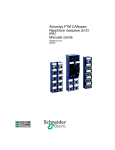
CANopen Slave Device
CAN-2024C
Application User’s Manual
Warranty
Without contrived damage, all products manufactured by ICP DAS are
warranted in one year from the date of delivery to customers.
Warning
ICP DAS revises the manual at any time without notice. However, no
responsibility is taken by ICP DAS unless infringement act imperils to patents
of the third parties.
Copyright
Copyright © 2009 is reserved by ICP DAS.
Trademark
The brand name ICP DAS as a trademark is registered, and can be used
by other authorized companies.
CAN-2024C user’s manual (Revision 1.00, May/26/2010) ------
1
Contents
1
2
3
Introduction.............................................................................................3
1.1 Overview.........................................................................................3
1.2 Hardware Specifications ...............................................................4
1.3 Features..........................................................................................5
1.4 Application .....................................................................................5
Hardware .................................................................................................6
2.1 Structure.........................................................................................6
2.2 Node ID & Baud Rate Rotary Switch ............................................7
2.3 LED Description .............................................................................8
2.4 PIN Assignment .............................................................................9
2.5 Wire Connection ..........................................................................10
Object Dictionary .................................................................................. 11
3.1 Object List .................................................................................... 11
3.2
3.3
3.4
Store and Restore Object............................................................14
Application Object .......................................................................15
Default PDO Mapping ..................................................................19
CAN-2024C user’s manual (Revision 1.00, May/26/2010) ------
2
1 Introduction
1.1 Overview
CANopen is one kind of the network protocols based on the CAN bus and
mainly used for embedded network system, such as industrial machine control ,
vehicle control system, factory automation, medical equipments control,
remote data acquisition, environmental monitoring, and packaging machines
control, etc.
The CAN-2024C module follows the CiA DS-301 version 4.02 and
DSP-401 version 2.1. It is easy to access the analogue I/O status and set the
configuration by using the standard CANopen protocol. The CAN-2024C has
passed the validation of the CiA CANopen Conformance Test tool. Therefore,
the provided EDS file is standard for any other standard CANopen masters.
Owing to the 4-channel analog output and the CANopen masters of ICP DAS,
you can quickly build a CANopen network to approach your requirements.
Figure 1-1
CAN-2024C user’s manual (Revision 1.00, May/26/2010) ------
3
1.2 Hardware Specifications
Analogue Output:
z Output Channels: 4 single-end channels
z Output Type : 0 ~ +20 mA, 4 ~ +20 mA, 0 ~ +5 VDC, -5 VDC ~ +5 VDC,
z
z
z
z
z
z
z
z
z
z
0 ~ +10 VDC, -10 VDC ~ +10 VDC.
Resolution : 14-bit.
Accuracy: +/- 0.1% of FSR for Voltage Output.
+/- 0.2% of FSR for Current Output.
Zero Drift :Voltage:+/- 30µV/ °C.
Current: +/-0.2µA/ °C.
Span Drift :+/- 20ppm/ °C.
Voltage Output Capability: 10V@5mA.
Max Current Load Resistance: external power +24 V:1050 Ω.
Power-on Value & Safe value: Yes.
4KV ESD Protection: Yes, Contact for each terminal.
Intra-module Isolation, Field to Logic: 3000 VDC.
Others:
z CANopen Status: 3 LEDs for PWR / RUN / ERR.
z Terminator Resister: Yes, by DIP-switch with 1 LED indicator
z AO LED: 4 LEDs for analog output, and 4 LEDs for circuit output
z Power Supply: Unregulated +10 ~ +30 VDC.
z Power Consumption: 1.5 W.
z Operating Temperature: -25 ~ 75 ℃.
z Storage Temperature: -40 ~ 80 ℃.
z
z
Humidity: 5 to 95% RH, Non-condensing.
Dimensions: 32.5 mm x 110 mm x 102 mm (W x L x H) Detail.
CAN-2024C user’s manual (Revision 1.00, May/26/2010) ------
4
1.3 Features
z
z
z
z
z
z
z
z
z
Standard CANopen general I/O slave devices.
CANopen Version: DS-301, v4.02.
Device Profile: DSP-401, v2.1
Provide 4 single-end analog output channels.
CANopen transfer rate: 10 kbps, 20 kbps, 50 kbps, 125 kbps, 250
kbps, 500 kbps, 800 kbps, 1000 kbps.
Maximum CANopen slave Node-ID up to 99.
Support NMT, PDO, SDO, EMCY, SYNC, Guarding, and Heartbeat
protocol.
Pass the validation of CANopen conformance test
Provide EDS file for CANopen master interface
1.4 Application
Figure 1-2 Application Structure
CAN-2024C user’s manual (Revision 1.00, May/26/2010) ------
5
2 Hardware
2.1 Structure
Figure 2-1 (Top View)
Figure 2-2 (Bottom View)
CAN-2024C user’s manual (Revision 1.00, May/26/2010) ------
6
2.2 Node ID & Baud Rate Rotary Switch
The rotary switches of node ID configure the node ID of CAN-2024C
module. These two switches are for the tens digit and the units digit of the
node ID. The node ID value of this demo picture is 32.
Figure 2-3 Node ID rotary switch
The rotary switch of baud rate handles the CAN baud rate of CAN-2024C
module. The value of baud rate switch from 0 ~ 7 are normal CANopen mode,
The relationship between the rotary switch value and the practical baud rate is
presented in the following table.
Figure 2-4 Baud rate rotary switch
Rotary Switch Value
Baud Rate (k bps)
0
10
1
20
2
50
3
125
4
250
5
500
6
800
7
1000
Table 2-1
CAN-2024C user’s manual (Revision 1.00, May/26/2010) ------
7
2.3 LED Description
Power LED
CAN-2024C allows 10 VDC ~ 30 VDC for working voltage. The
power consumption is 1.5 W. Under the connection of a proper power
connection, as the unit is turned on, the LED will light up in red.
Run LED
The Run LED indicates the CANopen operation state. The
description of LED state is shown below. About the detail, please refer
to the section 2.3.1 of the CAN-2000C user manual.
LED Signal
State
Description
No Light
Non-operation
Power Supply is not ready
Single Flash
Stopped
The device is in Stopped state
Blinking
Pre-operational Device is in Pre-operational state
Continuing Light
Operational
Device is in Operational state
Table 2-2
Error LED
The Error LED indicates the CANopen error state. The
description of LED state is shown below. About the detail please refer
to the section 2.3.2 of the CAN-2000C user manual.
LED Signal
State
Description
No Light
No error
Device is working well.
Single Flash
Error Warning
At least one CANopen error
happened.
Double Flash
Guarding Fail
Guarding fail event happened.
Continuing Light
Bus Off
The bus off state happened.
Table 2-3
Terminal Resistor LED
When enable the 120Ω terminator resistor, the LED will turn on.
Vout LED
If the CAN-2024C is applied in voltage mode, the Vout LED is
turned on while the corresponding channel outputs a non-zero
voltage value.
Iout LED
If the CAN-2024C is applied in current mode, the Iout LED is
turned on while the corresponding channel outputs a non-zero current
value.
CAN-2024C user’s manual (Revision 1.00, May/26/2010) ------
8
2.4 PIN Assignment
Figure 2-7
CAN-2024C user’s manual (Revision 1.00, May/26/2010) ------
9
2.5 Wire Connection
Figure 2-8
CAN-2024C user’s manual (Revision 1.00, May/26/2010) ------
10
3 Object Dictionary
3.1 Object List
General Communication Entries
Idx
Sidx
Description
Type
Attr
Default
1000h
0h device type
UNSIGNED 32
RO
00300191h
1001h
0h error register
UNSIGNED 8
RO
0h
1003h
0h largest sub-index supported for UNSIGNED 8
RO
0h
UNSIGNED 32
RO
---
...
...
---
5h actual error (the oldest one)
UNSIGNED 32
RO
---
1005h
0h COB-ID of Sync message
UNSIGNED 32
RW
80h
1008h
0h manufacturer device name
VISIBLE_STRING
RO
CAN-2024C
1009h
0h manufacturer hardware version
VISIBLE_STRING
RO
02
100Ah
0h manufacturer software version
VISIBLE_STRING
RO 1.00-20100201
100Ch
0h guard time
UNSIGNED 16
RW
0h
100Dh
0h life time factor
UNSIGNED 8
RW
0h
1010h
0h largest sub-index supported for UNSIGNED 8
RO
1h
“predefine error field”
1h actual error (the newest one)
...
...
“store parameters”
1010h
1h save all hardware parameter
UNSIGNED 32
RW
---
1011h
0h largest sub-index supported for UNSIGNED 8
RO
1h
“restore default parameters”
1011h
1h restore all default parameters
UNSIGNED 32
RW
---
1014h
0h COB-ID of EMCY
UNSIGNED 32
RW
80h+x
1017h
0h producer heartbeat time
UNSIGNED 16
RW
0
1018h
0h largest sub-index supported for UNSIGNED 8
RO
4
“identity object”
1h vender ID
UNSIGNED 32
RO 0x0000013C
2h product code
UNSIGNED 32
RO
0x00002024
3h revision number
UNSIGNED 32
RO
0x00010001
4h serial number
UNSIGNED 32
RO
0x6cd3683c
Table 3-1
Note: x is Node-ID of the module
CAN-2024C user’s manual (Revision 1.00, May/26/2010) ------
11
SDO Communication Entries
Idx
Sidx
Description
Type
Attr
Default
1200h
0h
largest sub-index supported for
“server SDO parameter”
UNSIGNED 8
RO
2
1h
COB-ID form client to server UNSIGNED 32
(RxSDO)
RO 600h+x
2h
COB-ID form server to client UNSIGNED 32
(TxSDO)
RO 580h+x
Table 3-2
Note: x is Node-ID of the module
RxPDO Communication Entry
Idx
Sidx
1401h
0h
Description
Type
Attr
Default
Number of entries
UNSIGNED 8
RO
4
1h
COB-ID used by RxPDO
UNSIGNED 32
RW
300h+x
2h
Transmission type
UNSIGNED 8
RW
FFh
Type
Attr
Default
Table 3-3
Note: x is Node-ID of the module
RxPDO Mapping Communication Entry
Idx
Sidx
Description
1601h
0h
Number of entries
UNSIGNED 8
RW
4
1h
Write AO channel 0
UNSIGNED 16
RW
6411 0110h
2h
Write AO channel 1
UNSIGNED 16
RW
6411 0210h
3h
Write AO channel 2
UNSIGNED 16
RW
6411 0310h
4h
Write AO channel 3
UNSIGNED 16
RW
6411 0410h
Table 3-4
Analogue Output Function
Idx
Sidx
6411h
0h
Number of Output 8-Bit
UNSIGNED 16
RO
1
1h
AO value of channel 0
UNSIGNED 16 RW
0
2h
AO value of channel 1
UNSIGNED 16 RW
0
3h
AO value of channel 2
UNSIGNED 16 RW
0
4h
AO value of channel 3
UNSIGNED 16 RW
0
0h
Number of Analogue Outputs
UNSIGNED 8
RO
1
1h
Error Mode AO channel 0
UNSIGNED 8
RW
0
2h
Error Mode AO channel 1
UNSIGNED 8
RW
0
6443h
Description
Type
CAN-2024C user’s manual (Revision 1.00, May/26/2010) ------
Attr Default
12
6444h
2004h
3h
Error Mode AO channel 2
UNSIGNED 8
RW
0
4h
Error Mode AO channel 3
UNSIGNED 8
RW
0
0h
Number of Analogue Outputs
UNSIGNED 8
RO
4
1h
AO error value of channel 0
UNSIGNED 32 RW
0
2h
AO error value of channel 1
UNSIGNED 32 RW
0
3h
AO error value of channel 2
UNSIGNED 32 RW
0
4h
AO error value of channel 3
UNSIGNED 32 RW
0
0h
Number of Analogue Outputs
UNSIGNED 8
RO
4
1h
Type Code of AO Channel 0
UNSIGNED 8
RW
0x33
2h
Type Code of AO Channel 1
UNSIGNED 8
RW
0x33
3h
Type Code of AO Channel 2
UNSIGNED 8
RW
0x33
4h
Type Code of AO Channel 3
UNSIGNED 8
RW
0x33
Table 3-8
This object 0x2004 controls the output type of the CAN-2024C. There are six
kinds of output ranges for choices. These ranges and corresponding values
are listed below.
.
Type Code Value
Output Type
Output Range
Hexadecimal
0x30
Current
0 ~ 20 mA
0x0000 ~ 0x7FFF
0x31
Current
4 ~ 20 mA
0x0000 ~ 0x7FFF
0x32
Voltage
0 ~ 10 VDC
0x0000 ~ 0x7FFF
0x33 (default)
Voltage
-10 ~ +10 VDC
0x8000 ~ 0x7FFF
0x34
Voltage
0 ~ 5 VDC
0x0000 ~ 0x7FFF
0x35
Voltage
-5 ~ +5 VDC
0x8000 ~ 0x7FFF
CAN-2024C user’s manual (Revision 1.00, May/26/2010) ------
13
3.2
Store and Restore Object
Users can write the value 0x65766173 to the object index 0x1010 with
subindex 1 to save application setting, or write the value 0x64616F6C to object
index 0x1011 with subindex 1 to load the factory default. The following table
lists the relative objects which will be stored or restored after writing these two
objects. The factory default for these objects is also shown.
Index
Sub
Index
Description
Factory
Default
6443 h
1
Error Mode AO channel 0
0
2
Error Mode AO channel 1
0
3
Error Mode AO channel 2
0
4
Error Mode AO channel 3
0
1
AO error value of channel 0
0
2
AO error value of channel 1
0
3
AO error value of channel 2
0
4
AO error value of channel 3
0
1
Type Code of AO Channel 0
0x33
2
Type Code of AO Channel 1
0x33
3
Type Code of AO Channel 2
0x33
4
Type Code of AO Channel 3
0x33
6444 h
2004 h
CAN-2024C user’s manual (Revision 1.00, May/26/2010) ------
14
3.3 Application Object
Analogue Output module (0x6411)
User can use the object index 0x6411 with subindex 1 to read a group of
16-bit information. For example, if the node ID of the CAN-2024C is 1, the
commands are listed as below:
11-bit COB-ID (bit)
Func Code
RTR
Node ID
10
9
8
7
6
5
4
3
2
1
0
1
1
0
0
0
0
0
0
0
0
1
0
8-byte Data (byte)
Data
Length
8
0
1
2
3
4
5
6
7
40
11
60
01
00
00
00
00
SDO server
(CAN-2024C)
SDO client
11-bit COB-ID (bit)
Func Code
RTR
Node ID
10
9
8
7
6
5
4
3
2
1
0
1
0
1
1
0
0
0
0
0
0
1
0
8-byte Data (byte)
Data
Length
5
0
1
2
3
4
5
6
7
4B
00
60
01
FF
3F
--
--
SDO server
(CAN-2024C)
Read the object index 0x6411 with subindex 1, and the value 0x3FFF of the AO
channel 0 will be responded by CAN-2024C module.
SDO client
User can use the object index 0x6411 with subindex 1 to write output
value (Hex format) into CAN-2024C module. The commands are as follows.
11-bit COB-ID (bit)
Func Code
RTR
Node ID
10
9
8
7
6
5
4
3
2
1
0
1
1
0
0
0
0
0
0
0
0
1
0
8-byte Data (byte)
Data
Length
8
0
1
2
3
4
5
6
7
2B
11
64
01
FF
2F
00
00
SDO server
(CAN-2024C)
SDO client
11-bit COB-ID (bit)
Func Code
RTR
Node ID
10
9
8
7
6
5
4
3
2
1
0
1
0
1
1
0
0
0
0
0
0
1
0
8-byte Data (byte)
Data
Length
4
0
1
2
3
4
5
6
7
60
11
64
01
--
--
--
--
SDO server
(CAN-2024C)
Write the 0x2FFF value into the object index 0x6411 with subindex 1 of
CAN-2024C, and the AO channel 0 will output the 5V if you select the 0~10 V
output range.
SDO client
CAN-2024C user’s manual (Revision 1.00, May/26/2010) ------
15
Analogue Output Error Mode (0x6443)
This object defines whether an output is set to a pre-defined error value
(see 6444h object) in case of an internal device failure or a ‘Stop remote node’
indication.
0 = actual value rest.
1 = reverts to error value integer (6444h).
others= reserved.
For example, if the node ID of the CAN-2024C is 1, the commands are as
follows:
11-bit COB-ID (bit)
Func Code
RTR
Node ID
10
9
8
7
6
5
4
3
2
1
0
1
1
0
0
0
0
0
0
0
0
1
0
8-byte Data (byte)
Data
Length
8
0
1
2
3
4
5
6
7
2F
43
64
01
01
00
00
00
SDO server
(CAN-2024C)
SDO client
11-bit COB-ID (bit)
Func Code
RTR
Node ID
10
9
8
7
6
5
4
3
2
1
0
1
0
1
1
0
0
0
0
0
0
1
0
8-byte Data (byte)
Data
Length
4
0
1
2
3
4
5
6
7
60
02
60
01
--
--
--
--
SDO server
(CAN-2024C)
Write object index 0x6443 with subindex 1 to subindex 4, which can set each
channel for actual value rest mode or reverts to error value integer mode.
SDO client
Analogue Output Error Value Interger (0x6444)
On condition that the corresponding Error Mode is active, device failures
will set the outputs to the value configured by this object (index = 0x6444).
For example, if the node ID of CAN-2024C is 1, the commands are shown
below:
11-bit COB-ID (bit)
Func Code
RTR
Node ID
10
9
8
7
6
5
4
3
2
1
0
1
1
0
0
0
0
0
0
0
0
1
0
8-byte Data (byte)
Data
Length
8
0
1
2
3
4
5
6
7
23
44
64
01
FF
3F
00
00
SDO server
(CAN-2024C)
SDO client
CAN-2024C user’s manual (Revision 1.00, May/26/2010) ------
16
11-bit COB-ID (bit)
Func Code
RTR
Node ID
10
9
8
7
6
5
4
3
2
1
0
1
0
1
1
0
0
0
0
0
0
1
0
8-byte Data (byte)
Data
Length
4
0
1
2
3
4
5
6
7
60
44
64
01
--
--
--
--
SDO server
(CAN-2024C)
Write the output value 0x3FFF into the object index 0x6444 with subindex 1. The
CAN-2024C responds that it is successful.
SDO client
Type Code for CAN-2024C Module (index = 0x2004)
Setting the type code will decide the output ranges of the CAN-2024C. If
the node ID of the CAN-2024C is 1, the commands are listed as below:
11-bit COB-ID (bit)
Func Code
RTR
Node ID
10
9
8
7
6
5
4
3
2
1
0
1
1
0
0
0
0
0
0
0
0
1
0
8-byte Data (byte)
Data
Length
8
0
1
2
3
4
5
6
7
2F
04
20
01
34
00
00
00
SDO server
(CAN-2024C)
SDO client
11-bit COB-ID (bit)
Func Code
RTR
Node ID
10
9
8
7
6
5
4
3
2
1
0
1
0
1
1
0
0
0
0
0
0
1
0
8-byte Data (byte)
Data
Length
4
0
1
2
3
4
5
6
7
60
04
20
01
--
--
--
--
SDO server
(CAN-2024C)
Write the type code value 0x34 into the object with index 0x2004 and subindex 1.
The CAN-2024C responds that it is successful.
SDO client
Error Mode and Error Value (0x6443, 0x6444)
The object 0x6443 and 0x6444 are used to control the safe value when
the CAN-2024C is into stop mode or some error happens, such as node
guarding failure, it will check the value of the object 0x6443. If some bits of the
subindex 1 of this object are set to 1, the corresponding AO channels will
output the error mode output values which are described in the corresponding
subindex of the object 0x6444. For example, if set the value 1 into the object of
0x6443 with subindex 1 and a value 0x3FFF into the object 0x6444 with
subindex 1 respectively, when some error event occurs, only the channel 0 will
output the error mode output value 0x3FFF because the index 0x6443 with
subindex 1 is set to 1. The others channels keeps the status as the error event
is not happened.
CAN-2024C user’s manual (Revision 1.00, May/26/2010) ------
17
11-bit COB-ID (bit)
Func Code
RTR
Node ID
10
9
8
7
6
5
4
3
2
1
0
1
1
0
0
0
0
0
0
0
0
1
0
8-byte Data (byte)
Data
Length
8
0
1
2
3
4
5
6
7
2F
43
64
01
01
00
00
00
SDO server
(CAN-2024C)
SDO client
11-bit COB-ID (bit)
Func Code
RTR
Node ID
10
9
8
7
6
5
4
3
2
1
0
1
0
1
1
0
0
0
0
0
0
1
0
8-byte Data (byte)
Data
Length
8
0
1
2
3
4
5
6
7
60
43
64
01
--
--
--
--
SDO server
(CAN-2024C)
Write object index 0x6443 and subindex 1 to 0x01 means that setting the error
SDO client
mode to 0x01 for enabling the error mode output of channel 0.
11-bit COB-ID (bit)
Func Code
RTR
Node ID
10
9
8
7
6
5
4
3
2
1
0
1
1
0
0
0
0
0
0
0
0
1
0
8-byte Data (byte)
Data
Length
8
0
1
2
3
4
5
6
7
23
44
64
01
FF
3F
00
00
SDO server
(CAN-2024C)
SDO client
11-bit COB-ID (bit)
Func Code
RTR
Node ID
10
9
8
7
6
5
4
3
2
1
0
1
0
1
1
0
0
0
0
0
0
1
0
8-byte Data (byte)
Data
Length
8
0
1
2
3
4
5
6
7
60
44
64
01
--
--
--
--
SDO server
(CAN-2024C)
Write object index 0x6444 and subindex 1 to 0x3FFF means that setting the error
value to 0x3FFF for activating the error mode output value of channel 0. If the
error event occurs, the module will output the safe value 0x3FFF corresponding
the object 0x6443 and 0x6444.
SDO client
CAN-2024C user’s manual (Revision 1.00, May/26/2010) ------
18
3.4 Default PDO Mapping
RxPDO mapping list:
ID
Len
D0
D1
D2
D3
D4
D5
D6
D7
300h + x
8
AO_
C0_L
AO_
C0_H
AO_
C1_L
AO_
C1_H
AO_
C2_L
AO_
C2_H
AO_
C3_L
AO_
C3_H
Table 3-9
Default RxPDO list
Note: x is Node-ID of the module
Note: AO is Analogue Output
Note: C0, C1, C2 and C3 is channel 0, channel 1, channel 2 and channel 3.
Note: The ‘L’ indicates low byte and ‘H’ indicates high byte.
CAN-2024C user’s manual (Revision 1.00, May/26/2010) ------
19