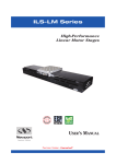
1
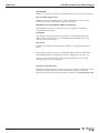
XM Series
SP
E
CI
ANTE
NS
AR
ED
GU
Ultra-Precision
Linear Motor Stages
F I C AT
IO
RoHS
Compliant
USER’S MANUAL
XM Series
Ultra-Precision Linear Motor Stages
Warranty
Newport Corporation warrants this product to be free from defects in
material and workmanship for a period of 1 year from the date of
shipment. If found to be defective during the warranty period, the product
will either be repaired or replaced at Newport’s discretion.
To exercise this warranty, write or call your local Newport representative,
or contact Newport headquarters in Irvine, California. You will be given
prompt assistance and return instructions. Send the instrument,
transportation prepaid, to the indicated service facility. Repairs will be
made and the instrument returned, transportation prepaid. Repaired
products are warranted for the balance of the original warranty period, or
at least 90 days.
Limitation of Warranty
This warranty does not apply to defects resulting from modification or
misuse of any product or part.
CAUTION
Warranty does not apply to damages resulting from:
CAUTION
Please return equipment in
the original (or equivalent)
packing.
You will be responsible for
damage incurred from
inadequate packaging if the
original packaging is not
used.
• Incorrect usage:
– Load on the stage greater than maximum specified load.
– Carriage speed higher than specified speed.
– Improper grounding.
¬ Connectors must be properly secured.
¬ When the load on the stage represents an electrical risk, it must
be connected to ground.
– Excessive or improper cantilever loads.
• Modification of the stage or any part thereof.
This warranty is in lieu of all other warranties, expressed or implied,
including any implied warranty of merchantability or fitness for a
particular use. Newport Corporation shall not be liable for any indirect,
special, or consequential damages.
No part of this manual may be reproduced or copied without the prior
written approval of Newport Corporation.
This manual has been provided for information only and product
specifications are subject to change without notice. Any changes will be
reflected in future printings.
EDH0213En1020 — 07/15
ii
XM Series
Ultra-Precision Linear Motor Stages
Table of Contents
Warranty .................................................................................................................ii
EC Declaration of Conformity...............................................................................v
Definitions and Symbols.......................................................................................vi
Warnings ...............................................................................................................vii
Cautions .................................................................................................................ix
1.0
— Introduction .................................................................................1
2.0
— Description ...................................................................................2
2.1 Design Details ............................................................................................3
3.0
3.1
3.2
3.3
3.4
3.5
3.6
4.0
— Characteristics ............................................................................3
Definitions ..................................................................................................3
Mechanical Specifications .......................................................................5
Load Characteristics and Stiffness .........................................................5
Stage Weights ............................................................................................5
Example of Parameters “ScalingAcceleration” & “AccelerationLimit”...6
Estimated Moving Mass for XM Series Stages.......................................8
— Drive ................................................................................................9
4.1 Brushless Motors Characteristics ..........................................................9
4.2 Feedback Signal Position .........................................................................9
4.3 Pinouts........................................................................................................9
Motor (SUB-D9M Connector)...................................................................9
Encoder (SUB-D15M Connector)...........................................................10
Thermistance (SUB-D9F Connector) ....................................................10
5.0
— Connection to Newport Controllers ..............................11
5.1 Warnings on Controllers ........................................................................11
5.2 Connection...............................................................................................12
5.3 Cables .......................................................................................................12
6.0
— Connection to Non-Newport Electronics ....................13
6.1 Connections .............................................................................................13
7.0
— Dimensions .................................................................................14
8.0
— Accessories .................................................................................15
8.1 Granite Base for Ultra Surface Flatness................................................15
iii
EDH0213En1020 — 07/15
XM Series
Ultra-Precision Linear Motor Stages
9.0
— Maintenance ..............................................................................16
9.1 Maintenance ............................................................................................16
9.2 Repair .......................................................................................................16
9.3 Calibration ...............................................................................................16
Service Form .........................................................................................................17
EDH0213En1020 — 07/15
iv
XM Series
Ultra-Precision Linear Motor Stages
EC Declaration of Conformity
XM Series
EC Declaration of Conformity
following Annex II-1A
of Directive 2006/42/EC on machinery
The manufacturer:
MICRO-CONTROLE Spectra-Physics,
9 rue du Bois Sauvage
F-91055 Evry FRANCE
Hereby declares that the machinery:
Description: " XM "
Function: Ultra Precision Linear Motor Stage
Models: XML210, XML350, XMS50, XMS100, XMS160
– the technical file of which was compiled by:
Mr Dominique DEVIDAL, Quality Director,
MICRO-CONTROLE Spectra-Physics, Zone Industrielle - B.P.29
F-45340 Beaune La Rolande France
– complies with all the relevant provisions of the Directive 2006/42/EC on machinery.
– complies with all the relevant provisions of the Directive 2014/30/EU relating to electromagnetic compatibility.
– was designed and built in accordance with the following harmonised standards:
NF EN 61326-1:2013 « Electrical equipment for measurement, control and
laboratory use – EMC requirements – Part 1: General requirements »
NF EN 55011:2010/A1:2011 Class A
– was designed and built in accordance with the following other standards:
NF EN 61000-4-2
NF EN 61000-4-3
NF EN 61000-4-4
NF EN 61000-4-6
NF EN 61000-4-8
ORIGINAL DECLARATION
Done in Beaune La Rolande on 26 June 2015
Dominique DEVIDAL
Quality Director
DC1-EN rev:A
v
EDH0213En1020 — 07/15
XM Series
Ultra-Precision Linear Motor Stages
Definitions and Symbols
The following terms and symbols are used in this documentation and also
appear on the product where safety-related issues occur.
General Warning or Caution
The exclamation symbol may appear in warning and caution tables in this
document. This symbol designates an area where personal injury or
damage to the equipment is possible.
The following are definitions of the Warnings, Cautions and Notes that may
be used in this manual to call attention to important information regarding
personal safety, safety and preservation of the equipment, or important
tips.
WARNING
Warning indicates a potentially dangerous situation which can result in
bodily harm or death.
CAUTION
Caution indicates a potentially hazardous situation which can result in
damage to product or equipment.
NOTE
Note indicates additional information that must be considered by the
user or operator.
European Union CE Mark
The presence of the CE Mark on Newport Corporation equipment means
that it has been designed, tested and certified as complying with all
applicable European Union (CE) regulations and recommendations.
Warnings and Cautions
ATTENTION
This stage is a Class A device. In a residential environment, this device
can cause electromagnetic interference. In this case, suitable measures
must be taken by the user.
EDH0213En1020 — 07/15
vi
XM Series
Ultra-Precision Linear Motor Stages
Warnings
WARNING
The motion of objects of all types carries potential risks for operators.
Ensure the protection of operators by prohibiting access to the dangerous
area and by informing the personnel of the potential risks involved.
WARNING
The magnetic channel included in this device has the potential to disrupt
pacemakers. Consequently, it is recommended that individuals maintain a
distance of 1 meter or more from the stage as a precautionary measure.
WARNING
Do not use this stage when its motor is emitting smoke or is unusually
hot to the touch or is emitting any unusual odor or noise or is in any
other abnormal state.
Stop using the stage immediately, switch off the motor power and then
disconnect the electronics power supply.
After checking that smoke is no longer being emitted contact your
Newport service facility and request repairs. Never attempt to repair the
stage yourself as this can be dangerous.
WARNING
Make sure that this stage is not exposed to moisture and that liquid does
not get into the stage.
Nevertheless, if any liquid has entered the stage, switch off the motor
power and then disconnect the electronics from power supply.
Contact your Newport service facility and request repairs.
WARNING
Do not insert or drop objects into this stage, this may cause an electric
shock, or lock the drive.
Do not use this stage if any foreign objects have entered the stage.
Switch off the motor power and then disconnect the electronics power
supply.
Contact your Newport service facility for repairs.
WARNING
Do not place this stage in unstable locations such as on a wobbly table or
sloping surface, where it may fall or tip over and cause injury.
If this stage has been dropped or the case has been damaged, switch off
the motor power and then disconnect the electronics power supply.
Contact your Newport service facility and request repairs.
W
vii
EDH0213En1020 — 07/15
XM Series
Ultra-Precision Linear Motor Stages
WARNING
Do not attempt to modify this stage; this may cause an electric shock or
downgrade its performance.
WARNING
Do not exceed the usable depth indicated on the mounting holes (see
section “Dimensions”). Longer screws can damage the mechanics or
cause a short-circuit.
WARNING
Do not exceed speed and load limitations as specified in chapter 3.3.
EDH0213En1020 — 07/15
viii
XM Series
Ultra-Precision Linear Motor Stages
Cautions
CAUTION
Do not place this stage in a hostile environment such as X-Rays, hard
UV,… or in any vacuum environment.
CAUTION
Do not place this stage in a location affected by dust, oil fumes, steam or
high humidity. This may cause an electric shock.
CAUTION
Do not leave this stage in places subject to extremely high temperatures
or low temperatures. This may cause an electric shock.
• Operating temperature: +10 to +35 °C
• Storage temperature: -10 to +40 °C (in its original packaging)
CAUTION
Do not move this stage if its motor power is on.
Make sure that the cable to the electronics is disconnected before
moving the stage. Failure to do so may damage the cable and cause an
electrical shock.
CAUTION
Be careful that the stage is not bumped when it is being carried. This
may cause it to malfunction.
CAUTION
When handling this stage, always unplug the equipment from the power
source for safety.
CAUTION
When the carriage is in its end-of-run position, it is strongly recommended
not to go beyond this point as this may damage the stage mechanism.
CAUTION
Contact your Newport service facility to request cleaning and
specification control every year.
CAUTION
You may have unfortunately put your fingers on the optical scale. This
can cause failures while the stage is operating. In order to obtain an
optimal operation, we advise to clean this optical scale with isopropylic
alcohol.
ix
EDH0213En1020 — 07/15
XM Series
EDH0213En1020 — 07/15
Ultra-Precision Linear Motor Stages
x
XM Series
Ultra-Precision Linear Motor Stages
Ultra-Precision Linear Motor Stages
XM Series
1.0 —Introduction
This manual provides operating instructions for the stage that you have
purchased in the XM Series.
XMS50, XMS160 and XML350 stages.
RECOMMENDATION
We recommend you read carefully the chapter “Connection to
electronics” before using the XM stage.
A typical XYZ assembly using XML210, XMS50 and GTS30V
1
EDH0213En1020 — 07/15
XM Series
Ultra-Precision Linear Motor Stages
2.0 —Description
The XM series is the ultimate solution for the most demanding
manufacturing and test & measurement applications. It meets ultraprecision motion requirements with high dynamics and reliability for 24/7
production environments. Typical applications include semiconductor
wafer inspection, direct laser lithography, sensor test-and calibration and
ultra-precision assembly.
Unlike screw driven stages, the XM stages employ a center-driven, ironless
linear motor as the driving element. Since the linear motor is a frictionless
direct drive device, there is no backlash or hysteresis, wind-up or stiction
limiting the motion performance. The linear motor drive also offers the
advantage of higher speed, acceleration and system responsiveness with
no wear to motor brushes or drive screws. The extra-large, ironless motor
coil ensures zero cogging for ultra-smooth velocity control at all speeds
and provides a higher efficiency compared to alternative stage designs.
This results in significant less heat dissipation which is generally the main
limit for ultra-precision motion applications. To further improve thermal
management and its effect on stage performance, the XM stages take also
benefit of a sophisticated length decoupling of the magnetic track from the
stage carriage.
XM stages are machined from stress-relieved 7075 aluminum ensuring
long-term strength and stability. All critical stage surfaces undergo
multiple machining processes and precision grinding under strict
temperature and quality control, to further improve overall performance
and accuracy. The T-shape carriage used on the XM stages provides the
optimum solution for precision XY assemblies without impacting the stage
preload. It also supplies a higher robustness and is more tolerant to nonideal mounting conditions than stages with a C-shape carriage.
To ensure the most accurate trajectory control, XM stages feature highclass matched pairs of anti-creep crossed roller bearings. The lack of any
re-circulating elements in the XM stages lead to outstanding ripple-free
motion adequate for the most demanding scanning and inspection
systems. Moreover, the geared retainers on these bearings prevent from
bearing cage migration, which can occur with other linear bearings.
Precision position feedback is supplied by a high accuracy LIF 481
Heidenhain linear scale. The precision alignment and mounting of this low
thermal expansion scale in the center of the stage minimizes the impact of
temperature changes on stage repeatability and accuracy. The encoder
signals are interpolated by Newport’s XPS motion controller with sub-nm
resolution and less than 10 nm noise for outstanding position sensitivity
and stability. Absolute home position and limit signals are incorporated on
the same scale without any further electronics or mechanics for improved
reliability and accuracy. In general, all electronics are attached to the
stationary base. So there are no moving cables inside the stage resulting in
an extremely compact design with exceptional reliability and safety.
EDH0213En1020 — 07/15
2
XM Series
Ultra-Precision Linear Motor Stages
2.1
Design Details
Base material
Bearings
Drive mechanism
Motor initialization
Motor commutation
Feedback
Limit switches
Origin
Drive type
Cable
High-strength 7075 Aluminum
Anti-creep crossed roller bearings
3-phase synchronous ironless linear motor (without Hall effect sensors)
Utilizes XPS controller patented feature that avoids large motions during initialization,
without using Hall effect sensors
Done by the XPS controller using encoder signals
Heidenhain LIF 481 scale, 1 Vpp, 4 µm signal period, 32768-fold signal subdivision when used
with XPS controller
Optical, on encoder's fiducial track
Optical, at center of travel, including mechanical zero signal
Brushless DC Servo
5 m (included)
NOTE
RoHS
This product complies with the RoHS directive
(Restriction of Hazardous Substances).
Compliant
3.0 —Characteristics
3.1
Definitions
Specifications of our products are established in reference to ISO 230
standard part II “Determination of accuracy and repeatability of
positioning numerically controlled axes”.
This standard gives the definition of position uncertainty which depends
on the 3 following parameters:
(Absolute) Accuracy
Difference between ideal position and real position.
On-Axis Accuracy
Difference between ideal position and real position after the compensation
of linear errors.
Linear errors include: cosine errors, inaccuracy of screw or linear scale
pitch, angular deviation at the measuring point (Abbe error) and thermal
expansion effects. All Newport motion electronics can compensate for
linear errors.
The relation between absolute accuracy and on-axis accuracy is as follows:
Absolute Accuracy = On-Axis Accuracy + Correction Factor x Travel
R
3
EDH0213En1020 — 07/15
XM Series
Ultra-Precision Linear Motor Stages
Repeatability
Ability of a system to achieve a commanded position over many attempts.
Reversal Value (Hysteresis)
Difference between actual position values obtained for a given target
position when approached from opposite directions.
Minimum Incremental Motion (MIM or Sensitivity)
The smallest increment of motion a device is capable of delivering
consistently and reliably.
Resolution
The smallest increment that a motion device can theoretically move
and/or detect. Resolution is not achievable, whereas MIM, is the real
output of a motion system.
Yaw, Pitch
Rotation of carriage around the Z axis (Yaw) or Y axis (Pitch), when it
moves.
The testing of on-axis accuracy, repeatability, and reversal error are made
systematically with test equipment in an air-conditioned room (20 ±1 °C).
A linear cycle with 21 data points on the travel and 4 cycles in each
direction gives a total of 164 points.
Guaranteed Specifications
Guaranteed maximum performance values are verified per Newport's A167
metrology test procedure. For more information, please consult the
metrology tutorial section in the Newport catalog or at www.newport.com
EDH0213En1020 — 07/15
4
XM Series
Ultra-Precision Linear Motor Stages
SP
E
CI
Travel range (mm)
Minimum Incremental Motion, linear (4) (5) (with XPS-DRV02 Drive)
Minimum Incremental Motion, linear (4) (5) (with XPS-DRV02P Drive Module)
Minimum Incremental Motion, linear (4) (5) (with XPS-DRV02L Drive Module)
Uni-directional repeatability, guaranteed (1) (4) (µm)
Bi-directional repeatability, guaranteed (1) (4) (µm)
On-axis accuracy, guaranteed (1) (4) (µm)
Maximum speed (5) (mm/s)
Maximum acceleration (5) (m/s2)
Max. force (cont.) (5) (N)
Load capacity, horizontal (N)
Straightness, flatness, guaranteed (1) (2) (µm)
Pitch, guaranteed (1) (2) (4) (µrad) (3)
Yaw, guaranteed (1) (2) (4) (µrad) (3)
MTBF (h)
ANTE
NS
AR
Mechanical Specifications
ED
GU
3.2
F I C ATI O
1)
2)
3)
4)
5)
XMS
50, 100, 160
0.01
0.003
0.001
0.05
0.08 or ±0.04
1.5 or ±0.75
300
5
16
100
1.5 or ±0.75
50 or ±25
50 or ±25
20,000
XML
210, 350
0.01
0.003
0.001
0.05
0.08 or ±0.04
3 or ±1.5
300
5
37
300
3 or ±1.5
100 or ±50
100 or ±50
20,000
Shown are peak to peak, guaranteed specifications or ±half the value as sometimes shown. For the definition of
typical specifications which are about 2X better than the guaranteed values, visit www.newport.com for the
Motion Control Metrology Primer.
Middle 80% of travel.
To obtain arcsec units, divide µrad value by 4.8.
Requires operation in a controlled environment to achieve specification.
Maximum value is driver dependent. Contact Newport for additional information.
CAUTION
To reach specifications stated, stages must be fixed on a plane surface
with a flatness of 5 µm.
3.3
Load Characteristics and Stiffness
Normal Load Capacity (Cz)
Maximum load a stage can move while maintaining specifications.
Z
Q
D
x
kαy
X
kα
Cz
kαz
3.4
Y
Cz, Normal centered load capacity (N)
kax, Compliance in roll (µrad/Nm)
kay, Compliance in pitch (µrad/Nm)
kaz, Compliance in yaw (µrad/Nm)
a, Construction parameter (mm)
Q, Off-center load
where D = Cantilever distance in mm
XMS50
100
3.5
3.5
3.5
109
XMS100
100
2.0
2.0
2.0
109
XMS160
XML210
100
300
1.5
0.5
1.5
0.5
1.5
0.5
109
155
Q ≤ Cz ÷ (1 + D/a)
XML350
300
0.1
0.1
0.1
155
Stage Weights
Weights indicated into the below table are average values for stages with a
typical drive unit installed.
XMS50
XMS100
XMS160
XML210
XML350
5
Stage
5.5 (2.5)
7.7 (3.5)
9.9 (4.5)
28.7 (13.0)
48.5 (22.0)
Mass [lb (kg)]
Carriage Mcar
2.6 (1.2)
4.0 (1.8)
5.1 (2.3)
16.8 (7.6)
26.0 (11.8)
EDH0213En1020 — 07/15
XM Series
Ultra-Precision Linear Motor Stages
3.5
Example of Parameters “ScalingAcceleration” & “AccelerationLimit”
This example is based on Newport XPS controller and XPS-DRV02 driver.
Two parameters have to be updated in the parameter file, according to the
payload put onto the XM stage:
• The parameter "ScalingAcceleration" is used by the controller to scale
the output voltage sent to the driver.
It indicates the theoretical maximum acceleration (friction not taken in
account) of the XM carriage when the maximum voltage (10 volts) is
applied to the driver.
• The parameter "AccelerationLimit" indicates the theoretical maximum
acceleration that the controller will be able to require from the
XM carriage. It correspond to the XM peak force.
For XPS controller and XPS-DRV02 driver, these parameters can be
calculated using the following formulas, where the payload must be entered
in kg:
XMS ScalingAcceleration(Payload) = 70357 .
[mm/s2]
(Payload + Mcar)
XML ScalingAcceleration(Payload) = 97232 .
[mm/s2]
(Payload + Mcar)
XMS160 Examples:
ScalingAcceleration(0) = 30590 mm/s2
ScalingAcceleration(10) = 5720 mm/s2
AccelerationLimit(Payload) =
ScalingAcceleration(Payload)
1.1
XMS60 Examples:
AccelerationLimit(0) = 27809 mm/s2
AccelerationLimit(10) = 5200 mm/s2
These formulas are explained below:
Inputs from the system
• Motor:
– Motor force constant:
XMS: MotorForceConstant = 19.9 N/Amp. rms
XML: MotorForceConstant = 27.5 N/Amp. rms
– Motor thermal resistance:
XMS: MotorRth = 1.8
XML:
MotorRth = 1.3
K
[ Watt
]
K
[ Watt
]
– Motor constant at 300 K:
2
XMS: MotorK = 24
[ Newton
Watt ]
XML:
[ Newton
Watt ]
2
MotorK = 97
• Driver:
XPS-DRV02 driver is using sine/cosine commutation on its input. Its
maximum current of 5 A is obtained for a 10 V input, so:
MaxDriverCurrent = 5 Amp.
TransImpedenceDriver = 0.5 Amp./V
EDH0213En1020 — 07/15
6
XM Series
Ultra-Precision Linear Motor Stages
• Mechanics:
– XM carriage mass:
See chapter: “Stage Weights” below.
• System:
XM rms force is defined to keep motor heating below 20 °C:
20 • [K] •MotorK
MotorRth
XMS_RmsForce = 16 Newtons
XM_RmsForce =
XML_RmsForce = 37 Newtons
XM peak force is defined to allow two time the rms force. This value is
lower than the theoretical peak force of the motor:
XMS_PeakForce = 32 Newtons
XML_PeakForce = 74 Newtons
The rms current limitation of the driver is set according to XM rms
force:
Amp.
XM_RmsForce
2
Amp. rms
MotorForceConstant
XMS DriverMaximumRMSCurrent = 1.14 Amp.
[
DriverMaximumRMSCurrent =
]
XML DriverMaximumRMSCurrent = 1.90 Amp.
The peak current limitation of the driver is set according to XM peak
force:
æ XM_PeakForce
ö
Amp.
•1.1; MaxDriverCurrent÷
DriverMaximumPeakCurrent = min ç
2
Amp. rms
è MotorForceConstant
ø
XMS DriverMaximumPeakCurrent = 2.5 Amp.
[
]
XML DriverMaximumPeakCurrent = 4.2 Amp.
The integration time of the driver I2t limitation is set to allow to apply
the peak current for 4 seconds. This is obtained with an integration time
of 15 s, which is lower than the motor thermal time constant.
DriverRMSIntegrationTime = 15 s
Example for a XML210 stage with a 3 kg load
Inputs from the user
– Load on the carriage:
Load = 3 kg
Calculation
• MovingMass:
MovingMass = Mcar + Load
• ScalingAcceleration:
ScalingAcceleration =
MotorForceConstant •10 [Volts] • TransImpedenceDriver
Amp.
•(Mcar + Load)
2
Amp. rms
ScalingAcceleration = 9172 mm/s
[
]
2
• LimitAcceleration:
LimitAcceleration = ScalingAcceleration•
DriverMaximumPeakCurrent 1
•
MaxDriverCurrent
1.1
LimitAcceleration = 27856 mm/s 2
7
EDH0213En1020 — 07/15
XM Series
Ultra-Precision Linear Motor Stages
3.6
Estimated Moving Mass for XM Series Stages
CAUTION
Stages with linear motor such as those of the XM series, are sensitive to
the load variation and its stiffness. The typical example below shows
the behavior of the displacement in accordance with the
underestimated/overestimated moving mass.
Z
Q
D
x
kα
kαy
Y
kαz
Cz
X
Driving in force requires a good adjustment of the controller/driver
theoretical acceleration parameter (ScalingAcceleration) which depends
on the moving mass.
Moving mass too high vs adjustment
Moving mass too low vs adjustment
+x
Displacement (µm)
Displacement (µm)
+x
0
-x
0
t
0
-x
2t
0
t
Time (s)
Time (s)
Moving mass good vs adjustment
Displacement (µm)
+x
0
-x
0
t
Time (s)
EDH0213En1020 — 07/15
8
2t
2t
XM Series
Ultra-Precision Linear Motor Stages
4.0 —Drive
4.1
Motor
Stage
UM3S
UL3S
XM-S
XM-L
Motor
Constant
(N2/W)
24
97
4.2
Brushless Motors Characteristics
Magnet
Pitch
(mm)
30
42
Nominal
Voltage
(V)
48
48
Max. Peak
Current
(A)
2.5
4.2
Resistance
per Phase
(Ω)
5.5
2.6
Inductance
per Phase
(mH)
1.6
2
Feedback Signal Position
1
Encoder
Phase A
Encoder
Phase A
Encoder
Phase B
Encoder
Phase B
2
3
4
1
0
1
Direction +
0
1
0
1
0
Direction –
4.3
Max. RMS
Current
(A)
1.1
1.9
Motion
Direction +
Pinouts
Sub-D connections for XM series stages are given in the following tables:
4.2.1
Motor (SUB-D9M Connector)
1
6
9
5
9
1
U Motor
2
U Motor
3
V Motor
4
V Motor
5
N.C.
6
W Motor
7
W Motor
8
Shield Ground
9
N.C.
EDH0213En1020 — 07/15
XM Series
Ultra-Precision Linear Motor Stages
4.2.2
Encoder (SUB-D15M Connector)
1
9
15
4.2.3
Encoder Phase B
2
Shield Ground
3
Encoder Phase A
4
Encoder Power: +5 V
5
N.C.
6
Limit
7
Index Pulse /I
8
Home
9
Encoder Phase /B
10
N.C.
11
Encoder Phase /A
12
N.C.
13
N.C.
14
Index Pulse I
15
N.C.
Thermistance (SUB-D9F Connector)
1
5
EDH0213En1020 — 07/15
8
1
10
6
9
1
Do not connect
2
Do not connect
3
N.C.
4
N.C.
5
Do not connect
6
Thermistance 2
7
Shield Ground
8
Thermistance 1
9
Shield Ground
XM Series
Ultra-Precision Linear Motor Stages
5.0 —Connection to Newport Controllers
5.1
Warnings on Controllers
Controllers are intended for use by qualified personnel who recognize
shock hazards and are familiar with safety precautions required to avoid
possible injury. Read the controller user’s manual carefully before
operating the instrument and pay attention to all written warnings and
cautions.
WARNING
Disconnect the power plug under the following circumstances:
• If the power cord or any attached cables are frayed or damaged in
any way.
• If the power plug is damaged in any way.
• If the unit is exposed to rain, excessive moisture, or liquids are spilled
on the unit.
• If the unit has been dropped or the case is damaged.
• If you suspect service or repair is required.
• Whenever you clean the electronics unit.
CAUTION
To protect the unit from damage, be sure to:
• Keep all air vents free of dirt and dust.
• Keep all liquids away from the unit.
• Do not expose the unit to excessive moisture (85% humidity).
• Read this manual before using the unit for the first time.
WARNING
All attachment plug receptacles in the vicinity of this unit are to be of
the grounding type and properly polarized.
Contact your electrician to check your receptacles.
WARNING
This product operates with voltages that can be lethal.
Pushing objects of any kind into cabinet slots or holes, or spilling any
liquid on the product, may touch hazardous voltage points or short out
parts.
11
EDH0213En1020 — 07/15
XM Series
Ultra-Precision Linear Motor Stages
5.2
Connection
On each stage is represented a label which indicates its name and its serial
number.
WARNING
Always turn the controller's power OFF before connecting to a stage.
Stages may be connected to the rear panel motor connectors any time
prior to power-up with the supplied cable assemblies.
NOTE
These stages are ESP compatible. Enhanced System Performance is
Newport's exclusive technology that enables Newport ESP motion
controllers to recognize the connected Newport ESP stage and upload
the stage parameters. This ensures that the user can operate the motion
system quickly and safely.
5.3
Cables
Our stages are delivered equipped with a set of three 5-meter cables. They can
be directly connected to to our controllers/drivers.
WARNING
XM Series translation stages operate only with 5-meter max. cables.
WARNING
These cables are shielded correctly. For a correct operation, make sure
to lock connectors (ground continuity provided by cables).
WARNING
Keep the motor cables at a safe distance from other electrical cables in
your environment to avoid potential cross talk.
EDH0213En1020 — 07/15
12
XM Series
Ultra-Precision Linear Motor Stages
6.0 —Connection to Non-Newport Electronics
Connections
WARNING
Newport is not responsible for malfunction or damage to a XM stage
when it is used with non- Newport controllers.
WARNING
Newport guarantees “ ” compliance of the XM stages only if they are
used with Newport cables and controllers.
Nevertheless, the figure below shows the wiring when a XM stage is
used with non-Newport controllers.
SUB-D9M
Connector
SUB-D9F
Connector
Motor
1
2
3
4
6
7
U Motor
U Motor
V Motor
V Motor
W Motor
W Motor
8
Connector
Cap
Ground
Connector
Cap
Encoder
SUB-D15M
Connector
SUB-D15F
Connector
3
11
1
9
14
7
4
6
8
Encoder Phase A
Encoder Phase /A
Encoder Phase B
Encoder Phase /B
Index Pulse I
Index Pulse /I
+5 V
Limit
Home
2
Connector
Cap
Thermistance
6.1
Ground
Connector
Cap
SUB-D9F
Connector
SUB-D9M
Connector
6
8
Thermistance 2
Thermistance 1
7
Connector
Cap
Ground
Connector
Cap
WARNING
+End-of-Run and -End-of-Run signals are not directly supplied by XM
series stages.
-End-of-Run
+End-of-Run
Limit
Home
Stage Travel Range
Motion
Direction +
They must be restored using “Limit” and “Home” signals which are
generated.
13
EDH0213En1020 — 07/15
XM Series
Ultra-Precision Linear Motor Stages
7.0 —Dimensions
XML STAGES ONLY:
4 HOLES M6 THD, THRU
XML STAGES ONLY:
4 HOLES M6 THD ON SQR 5.91 (150), THRU
2 x 4 HOLES M6 THD, THRU
EXCEPT XML STAGES, DEPTH: .47 (12)
[ ] 2.00 (100.8)
DIMENSIONS IN INCHES (AND MILLIMETERS)
4 HOLES M4 THD, DEPTH: .24 (6)
ON 3.94 x 2.95 (100 x 75)
1.97
(50)
XMS STAGES ONLY:
4 HOLES M4 THD, DEPTH: .24 (6)
SQR 2.98 (75.6)
[ ]
3.94
(100)
[ ]
2.00
(100.8)
1.97
(50)
EXCEPT XMS50:
4 HOLES M4 THD,
DEPTH: .24 (6)
ON B x C
21°
XML STAGES ONLY:
3 HOLES M5 THD,
AT 120° ON ø5.39 (137),
DEPTH: .24 (6)
ø.24 +.0005
0
(6 H7)
4 HOLES M6 THD, DEPTH: F
B
–
6.10 (155)
7.28 (185)
9.84 (250)
9.84 (250)
C
D
E
–
–
2.95 (75)
1.77 (45) 5.31 (135) 2.95 (75)
1.77 (45) 7.87 (200) 2.95 (75)
3.94 (100) 5.31 (135) 3.94 (100)
3.94 (100) 13.19 (335) 3.94 (100)
XMS50
XMS100
XMS160
XML210
XML350
F
.28 (7)
.28 (7)
.28 (7)
.47 (12)
.47 (12)
G
–
–
–
2.91 (74)
3.15 (80)
H
–
–
–
2.66 (67.5)
3.15 (80)
J
.39 (10)
.39 (10)
.39 (10)
.59 (15)
.59 (15)
K
.28 (7)
.59 (15)
.59 (15)
–
–
XMS & XML STAGE CONNECTORS:
SUB-D9M FOR MOTOR
SUB-D9F FOR END-OF-RUNS & THERMISTANCE
SUB-D15M FOR ENCODER
EXCEPT XMS50:
4 HOLES M4 THD, DEPTH: .24 (6)
ON EACH SIDE
XMS STAGES: EXIT FOR PIGTAIL CABLES
A
4.92 (125)
7.28 (185)
9.84 (250)
13.98 (355)
21.85 (555)
5.91
(150)
2.95 (75)
3.94 (100)
XMS50
XMS100
XMS160
XML210
XML350
XML STAGES: EXIT FOR CONNECTORS
.39 (10)
D
XMS: .41 (10.5)
XML: .61 (15.5)
.39 (10)
XMS: 1.97 (50)
XML: 3.15 (80)
XMS: 4.92 (125)
XML: 7.09 (180)
A
XML350 ONLY:
4 HOLES C’BORED (REF. B) FOR M6 SCREW,
THICKNESS UNDER SCREW HEAD: .59 (14.9)
XML STAGES
3.68 (93.5)
3.25 (82.5)
XMS STAGES
XMS160 ONLY:
4 HOLES C’BORED (REF. B) FOR M6 SCREW,
THICKNESS UNDER SCREW HEAD: .26 (6.5)
B2
A2
A3
3.39 (86)
J
B3
B2
4 HOLES C’BORED (REF. A) FOR M6 SCREW,
THICKNESS UNDER SCREW HEAD: .59 (14.9)
A2
K
B1
A1
3.94
(100)
B3
A4
B4
A4
B4
E
.26
(6.5)
B1 A1
G
A3
E
5.91 (150)
3.94
(100)
H
1.97
(50)
J
3.94 (100)
1.97
(50)
4 HOLES COUNTERBORED (REF. A) FOR M6 SCREW,
THICKNESS UNDER SCREW HEAD: .26 (6.5)
MOUNTING SURFACE, HEIGHT: .017 (.5)
CAUTION
Mounting screws of XM stage
magnetic channels are
accessible via the external side
of the top plate. They mustn’t be
unscrewed; this may damage
stage specifications.
EDH0213En1020 — 07/15
14
XM Series
Ultra-Precision Linear Motor Stages
8.0 —Accessories
8.1
Granite Base for Ultra Surface Flatness
The flatness of the surface is a major factor in the positioning accuracy
and repeatability of a motion system. Polished granite plates are among
the flattest, commercially available surfaces. Granite’s tight flatness
tolerance and extreme hardness make it logical option to complement
Newport’s Ultra-Precision Linear Motor XM series stage.
The GB series granite base plates (to order separately) feature 3 point
mounting, to make-up for non-flat tables. Edge handles facilitate handling
and locating the base plate on the work surface.
Model
GB50
GB100
GB160
GB210
GB350
15
Description
Granite Base for XMS50
Granite Base for XMS100
Granite Base for XMS160
Granite Base for XML210
Granite Base for XML350
EDH0213En1020 — 07/15
XM Series
Ultra-Precision Linear Motor Stages
9.0 —Maintenance
RECOMMENDATION
It is recommended to contact our After Sales Service which will know to
define the appropriate maintenance for your application.
9.1
Maintenance
The XM stage requires no particular maintenance. Nevertheless, this is a
precision mechanical device that must be kept and operated with caution.
PRECAUTIONS
The XM stage must be used or stocked in a clean environment, without
dust, humidity, solvents or other substances.
RECOMMENDATION
It is recommended to return your XM stage to Newport's After Sales
Service after every 2000 hours of use for lubrication.
If your stage is mounted on a workstation and cannot be easily
removed, please contact Newport's After Sales Service for further
instructions.
9.2
Repair
CAUTION
Never attempt to disassemble a component of the stage that has not
been covered in this manual.
To disassemble a non specified component can cause a malfunction of
the stage.
If you observe a malfunction in your stage, please contact us immediately
to arrange for a repair.
CAUTION
Any attempt to disassemble or repair a stage without prior
authorization will void your warranty.
9.3
Calibration
CAUTION
It is recommended to return your XM stage to Newport once a year for
recalibration to its original specifications.
EDH0213En1020 — 07/15
16
Service Form
Your Local Representative
Tel.:
Fax:
Name:
Return authorization #:
(Please obtain prior to return of item)
Company:
Address:
Date:
Country:
Phone Number:
P.O. Number:
Fax Number:
Item(s) Being Returned:
Model #:
Serial #:
Description:
Reasons of return of goods (please list any specific problems):
17
EDH0213En1020 — 07/15
Visit Newport Online at:
w w w. n e w p o r t . c o m
North America & Asia
Europe
Newport Corporation
MICRO-CONTROLE Spectra-Physics S.A.S
1791 Deere Ave.
Irvine, CA 92606, USA
9, rue du Bois Sauvage
91055 Évry CEDEX
France
Sales
Sales & Technical Support
Tel.: (800) 222-6440
Tel.: +33 (0)1.60.91.68.68
e-mail: [email protected]
e-mail: [email protected]
Technical Support
Service & Returns
Tel.: (800) 222-6440
Tel.: +33 (0)2.38.40.51.55
e-mail: [email protected]
Service, RMAs & Returns
Tel.: (800) 222-6440
e-mail: [email protected]