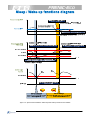
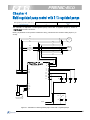
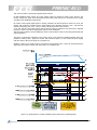
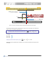
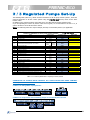
1
QUICK GUIDE
PUMP CONTROL
Frequency inverter for pump control and HVAC applications
Date
24/10/2008
Version
1.0.4
Version
1.0.3
Details
English Translation from
Spanish version 1.0.3
Date
19/09/2008
Pump Control Quick Guide
Applied
J. M. Ibáñez
J. Carreras
Revised
J. Català
M. Kitchen
Approved
2
Thank you for purchasing
is structured as follows:
,
Fuji Electric’s inverter for pump and fan applications. This guide
CHAPTER 0: Introduction to pressure control systems
9 types of pump control
5
CHAPTER 1: Single pump control
Electrical diagram
Sleep Function
Wake-up Function
Common parameters for pump control
Common parameters description
6
7
7
9
10
CHAPTER 2: Mono-regulated pump control with 1 regulated pump + 1,2,3 or 4 auxiliary pumps
Mono-regulated pump (mono-joker) control with 1 regulated pump + 1 auxiliary pump electrical diagram
Mono-regulated pump (mono-joker) control with 1 regulated pump + 2 auxiliary pumps electrical diagram
Mono-regulated pump (mono-joker) control with 1 regulated pump + 3 auxiliary pumps electrical diagram
Mono-regulated pump (mono-joker) control with 1 regulated pump + 4 auxiliary pumps electrical diagram
Connecting auxiliary pumps
Disconnecting auxiliary pumps
Common Parameters for pump control
Specific parameters
Specific parameters description
12
13
14
15
17
18
19
20
20
CHAPTER 3: Mono-regulated pump control with 1 regulated pump + 4 auxiliary pumps + 1 additional pump
Electrical diagram
Common parameters for pump control
Specific Parameters
Specific parameters description
22
24
25
25
CHAPTER 4: Multi-regulated pump (multi-joker) control with 2/3 regulated pumps
Multi-regulated pump (Multi-joker) control with 2 regulated pumps electrical diagram
Multi-regulated pump (Multi-joker) control with 3 regulated pumps electrical diagram
Connecting a regulated pump to commercial power supply
Disconnecting a regulated pump from commercial power supply
Common parameters for pump control
Specific parameters
Specific parameters description
Specific parameters description having optional card relay installed
27
28
30
30
32
33
33
34
CHAPTER 5: Multi-regulated pump (Multi-joker) control with 3 regulated pumps + 1 additional pump
Electrical diagram
Common parameters for pump control
Specific Parameters
Specific parameters description
35
37
38
39
Dry well function
Overpressure alarm
User units set-up
Start-up and switching motors sequence
Contactor delay time
Stopping mode selection when removing “RUN” signal (FWD or REV goes off)
Multiple PID set points selection
Dead band
Dew condensation prevention function
Integral PID component hold
Enable / disable pumps by means of external selectors
40
41
42
42
43
43
43
44
44
44
46
CHAPTER 6: Various Functions
CHAPTER 7: Function codes list. Digital and analog I/O functions
CHAPTER 8: Using TP-E1 keypad (basic keypad)
CHAPTER 9: Optional relay card OPC-F1-RY
Pump Control Quick Guide
47
53
54
3
The target of a pressure control system is to provide a variable flow with a constant pressure for the water
system of an apartment building, machine refrigeration systems, mixing liquids in chemical industry, etc.
A very typical example is providing the water supply for a residential building. In this case, the flow
(water consumption) is greater in the morning than during the night (when it’s almost non-existent) The
pressure control system must be able to provide, at the same pressure, both types of consumption
(DaytimeÆhigher flow, and during the nightÆ almost no flow); in addition, the system has to adapt to the
demand variations that occur normally in this kind of application, for example, when people turn taps on
and off at the same time.
inverter has been designed to fulfil all the requirements of the different pump control
The
systems. Some of its more important functions are:
•
•
•
•
•
•
•
•
•
•
•
•
•
•
•
•
•
•
•
•
•
•
•
•
Stop function due to low water flow (Sleep Function)
Start-up function because of water demand (Wake-up Function)
Software limits (current, voltage and frequency) to protect the motor and the pump
Control of multiple pumps on 1 regulated pump + auxiliary pumps topology (Mono-regulated
pump Control)
Control of multiple pumps on multi regulated pumps topology (Multi-regulated pump Control)
Possibility to add an additional pump (FDT Function) to both topologies
Many functions to avoid overpressure and water losses (Warnings, alarms, etc.)
Possibility of exact adjustment of the levels for start-up and stop of the auxiliary pumps to fine
tune system behaviour.
Possibility of the exact adjustment of the levels to start-up and stop of the PID control, during the
connection/disconnection of the auxiliary pumps, to fine tune system behaviour
Independent ramps for the start-up and the stop of the regulated pump, separate from the
ramps for the connection/disconnection of auxiliary pumps
Selection of the sequence for the pumps’ activation/deactivation
Sequenced switching rotation of the pumps (by timer or intelligent control)
Possibility of sharing the working time between the pumps
Information about the working time of each pump
Pressure sensor disconnection detection
Selecting different warnings (low-pressure, overpressure, etc.)
Protective function to protect pump from the absence of water (Dry well function)
“By-pass” sequence integrated
Control of the delay time between connection and disconnection of the contactors
Display units and sensor range adjustments
Selectable ‘Pump Stop’ Strategy?
Multiple frequency command selection (by means of digital inputs)
Dew condensation prevention Function
Safe energy Functions
Regulation by means of PID control:
A PID control is a regulation system involving the set value (SV - desired pressure) and a process value
(PV - Feedback, measure of real pressure or flow from a transducer). From these two values the
difference, or error, is calculated, subtracting one from the other. The PID control then adjusts its output
demand (MV - pump’s speed) in order to minimize the error:
-If the error is positive (desired pressure greater than real pressure) speed should increase
-If the error is negative (desired pressure lower than the real pressure) speed should decrease
-If the error is zero (desired pressure equal to real pressure) speed should stay at the same level
Parameters (gains) to adjust: Proportional, Integral and Derivative components (though Derivative
component is not normally used in this application) help to select how quickly the system will respond to
pressure and consumption changes. Normally, a quick (dynamic) response is desired, but pressure peaks
and oscillations must be avoided.
Pump Control Quick Guide
4
QUICK GUIDE
PUMP CONTROL
frequency inverter is able to control single or multiple pumps in mono-regulated or multiregulated configuration. Several control schemes may be built as shown below:
The necessary digital outputs will vary depending on the control type has been chosen (OPC-F1-RY
optional card may be necessary).
Necessary
digital outputs
Do we need the
optional relay card
installed?
Explained in…
0
NO
CHAPTER 1
Single pump control
Single pump control consists of 1 pump exclusively controlled by the frequency inverter
Necessary
digital outputs
Do we need the
optional relay card
installed?
1 auxiliary pump
(On-Off control)
1
NO
2 auxiliary pumps
(On-Off control)
2
NO
3 auxiliary pumps
(On-Off control)
3
NO
MONO-REGULATED PUMP CONTROL
up to 6 pumps (Mono-joker)
1
regulated
Pump
+
Explained in …
CHAPTER 2
4 auxiliary pumps
4
NO
(On-Off control)
1 additional
4 auxiliary
pump
pumps
5
NO
CHAPTER 3
+
(On-Off
(On-Off
control)
control)
Mono-regulated pump control consists of 1 pump exclusively controlled by the frequency inverter and
multiple auxiliary pumps working in On-Off control mode.
Additional pump is added / removed depending on the regulated pump speed and if auxiliary pumps are all
enabled or not.
Necessary
digital outputs
Do we need the
optional relay card
installed?
2 regulated pumps
4
NO
3 regulated pumps
6
YES
7
YES
MULTI-REGULATED PUMP CONTROL
up to 4 pumps (Multi-joker)
Explained in …
CHAPTER 4
3 regulated pumps
+
1 additional pump
(On-Off control)
CHAPTER 5
Pumps working on Multi-regulated mode are all inverter driven.
Additional pump is added / removed depending on the regulated pump speed and if others are also enabled
or not.
Pump Control Quick Guide
5
Single pump control
Necessary digital outputs
0
Do we need the optional relay card installed?
NO
When a regulated pump is being controlled, it’s necessary to consider certain parameters in order to allow
the inverter to control the pump’s start-up and stop, controlling speed to maintain the desired pressure,
etc.
The schematic to implement control by only 1 pump by means of
inverter, is as follows:
Please note the pressure transducer is connected to the inverter’s analog input C1 (4-20 mA)
Figure 1.1: control schematic for 1 pump only
By means of the keypad, a digital input or an analog set point, the desired pressure can be selected. Once
this pressure is set, inverter will modify pump’s speed between a minimum (J19 = F16 (Hz)) and a
maximum (J18=F15=F03 (Hz)) frequencies, in order to stabilize the pressure.
To work in this way, the integrated PID control must be enabled (J01) and adjusted properly. Then, the
inverter’s response should be the required action to control the application.
PID’s response can be modified by means of parameters J03 and J04 (Proportional gain and Integral time).
Pump Control Quick Guide
6
When the “RUN” signal is switched on (either FWD or REV), the inverter will increase the output frequency
(always after the period time defined in J38 (sec)). In order to control this rising output, some parameters
are available: F23 (Hz) controls the starting frequency, J43 the starting PID frequency and the ramp from
one to the other (F07) (sec.). Once J43 frequency level is achieved, PID control is enabled. In the same
way, when the “RUN” signal is switched off, the inverter decrease its output frequency to the level defined
in F25 (Hz) (the deceleration time is set in F08 (sec)), and stops the PID control.
Sleep Function (related parameters: J15 (Hz), J16 (sec.))
Sleep function can be useful to stop one pump when the speed is below a rate where there is no flow
(pump doesn’t impel).
Once the demand frequency level is below this rate (the frequency when the pump begins to move the
water but not enough to create a flow) is known, parameter J15 (Hz) should be set slightly higher than
this frequency.
Through this function, is possible to avoid possible mechanical problems that could (over time) damage
pump components or ‘boil’ the water with the wasted energy causing excess pressure and leaks. In
addition, stopping the pump when it’s not really needed means, obviously, Energy Saving.
So, Sleep Function will be applied if the inverter’s demand output frequency is lower than the ‘sleep’ level
stored in parameter J15 (Hz) and it stays at a lower level for a time longer than that specified in J16 (sec).
In Figure 1.2 sleep function is shown. The deceleration time to get to the “Stop Frequency” is stored in
F08 (sec.).
Important: Sleep frequency (J15 (Hz)) must be lower than the wake-up frequency (J17 (Hz)) and must be
higher than the minimum frequency (F16=J19)
Wake-up function (related parameters J17 (Hz), J23 (%), J24 (sec))
Wake-up function is useful to start-up a pump again that previously was stopped by the sleep function.
In order to wake up a pump, 3 conditions must be accomplished:
MV ≥ J17 (Hz)
Manipulated value (MV,
PID’s output) must be
greater than the level
stored in J17 (the current
MV value can be ridden
from 3. OPR MNTR
inverter’s menu.)
Delay Time ≥ J24
(sec)
|SV – PV|≥ J23 (%) (*)
and...
The absolute value of the process error
(the subtraction between the process
value and the set point value ) must be
greater than the percentage in J23
and...
Both conditions must be
met for longer than the
time specified in J24
(*) J23 is related with E40 and E41 function codes as follows: (|SV – PV|) / (E40 – E41) ≥ J23 (%), (E40
and E41 explained on page 42).
As the three conditions have to be met in order for the pump to start, multiple start-ups due to pipe losses
can be avoided. So, we avoid waking up the pump unnecessarily or too often.
In figure 1.2 is shown how the pump wakes up when accomplishes the three conditions.
Important: Sleep frequency (J15 (Hz)) must be lower than the wake-up frequency (J17 (Hz)).
In addition, sleep frequency must be higher than minimum frequency (F16=J19)
Pump Control Quick Guide
7
Figure 1.2: Speed control behaviour while sleep and wake-up functions are enabled
Pump Control Quick Guide
8
The following table (table 1.1), called “Common parameters to the all pump control systems”, shows the
, these are known as the basic
common parameters to all pump control systems using
parameters.
In other chapters, Specific Parameters’ table will be shown. These parameters will depend on the chosen
control system.
If you are adjusting the inverter by means of the TP-E1 keypad, is recommended to set E52 to “2”, in
order to be able to access to all the inverter menus.
Note: The following values are shown as an example and could not work properly in your application.
Common Parameters to all pump control systems
Name
F02
F07
F08
Run command
Acceleration Time 1
Deceleration Time 1
F11
Electronic Thermal Overload protection. Overload detection Level
F12
Electronic Thermal Overload protection. Time constant
F15
F16
F26
E40
E43
E62
P01
Frequency Limiter. High
Frequency Limiter. Low
Motor Sound. Carrier Frequency
PID Display coefficient A
LED monitor. Item selection
Analog Input for [C1]
Motor. Number of Poles
P02
Motor. Rated capacity
P03
Motor. Rated current
H91
J01
J03
J04
J15
J16
J17
J18
J19
J23
J24
C1 signal disconnection detection
PID Control. Mode Selection
PID Control. Gain P
PID Control. Gain I
PID Control. Stop frequency for slow flow rate
PID Control. Slow flow rate level stop latency
PID Control. Starting Frequency
PID Control. Upper limit of process output
PID Control. Lower limit of process output
PID Control. Starting From the Slow Flow rate Stop (Dev. Level)
PID Control. Starting From the Slow Flow rate Stop (Latency)
Default setting
Example’s Value
2
20.00 s
20.00 s
100% of the motor rated
current
5.0 min
10.0 min
(22kW or
(30kW or
below)
above)
70.0 Hz
0.0 Hz
15 kHz
+ 100.00
0
0
4
Rated Capacity Standard
Motor
Rated Current Standard
Motor
0.0 s
0
0.100
0.0 s
0 Hz
30 s
0 Hz
999
999
0%
0 sec
1
3.00 s
3.00 s
User’s Value
13.0 A
5 min
50.0 Hz
25.0 Hz
3 kHz
Transducer’s pressure
12
5
4
5.5 kW
13.0 A
0.5 s
1
2.500
0.2
35.0 Hz
15 s
38.0 Hz
50.0 Hz
25.0 Hz
5%
1 sec
Table 1.1: Common parameters to all pump control systems
CONDITIONS TO ACHIEVE GOOD CONTROL IN A SINGLE PUMP
If it’s necessary to use a different parameter set-up to that shown in the above “Example Values” column,
please bear in mind the following condition:
Sleeping/ Wake-up frequency Condition
Pump Control Quick Guide
9
COMMON PARAMETERS DESCRIPTION
Basic Function
F02: Run Command
This function code defines the way in what the “RUN” signal will be given to the inverter in order to start
the pressure control.
Usually, “Run Command” is sent to the inverter by means of the digital input (F02 = 1). That is, switching
on FWD or REV (control terminals in the inverter) digital inputs enables the inverter output.
A RUN command can be also activated by means of the keypad, pushing FWD or REV buttons (in TP-G1
keypad) or RUN in basic keypad (TP-E1).
F07: Acceleration Time 1
F08: Deceleration Time 1
These acceleration/deceleration ramps are used in two cases:
1.
After the Run Command is ON, F07 ramp is used to achieve the frequency in J43 or J19 (the
biggest one of both values).
When the Run Command is switched OFF, F08 value defines the deceleration ramp to go from the
current frequency to the stop frequency (F25).
2.
These ramps are also used when the inverter is connected/disconnected from the commercial
power supply if function codes J39 and J40 are set to 0.00 (please refer to the corresponding
diagrams in the following chapters).
F11: Electronic Thermal Overload Protection. Overload detection level
F12: Electronic Thermal Overload Protection. Thermal time constant
By means of these two parameters is possible to adjust the overload protection function. Normally, F11
will be adjusted to the motor’s rated current and F12 to 5 minutes.
F15: Frequency Limiter. High
F16: Frequency Limiter. Low
These two parameters define the frequency limits, and the inverter will never go outside of these limits
during pump control.
It’s normal to adjust the parameters F15, J18 and F03 with the same value.
Equally, F16 should be equal to J19, too.
Inputs Set-up
E62: Analog Input for [C1]
This parameter can be used to select the function for analog input C1.
Usually this parameter is set to E62 = 5, this setting will define the [C1] analog input as PID Feedback
(pressure transducer).
Motor Map
P01: Motor. Number of poles
P02: Motor. Rated Capacity
P03: Motor. Rated Current
In these parameters must be stored the number of poles, rated capacity and rated current as are shown in
the motor’s nameplate.
Pump Control Quick Guide
10
Special Functions
H91: C1 Signal disconnection Detection
Disconnection of pressure sensor (cable failure).
When a value is stored in parameter H91 (between 0.1 and 60.0 seconds) the inverter will generate an
alarm (CoF) when it notices that C1 signal current is missing (C1 current < 2mA) during a time longer
than the value in H91.
H91 = 0 Æ function disabled.
H91 ≠ 0 Æ function enabled.
PID and pump control
J01: PID control. Mode selection
When J01 = 1 and the error between Set Point and Process Value is positive (SP - PV > 0), the PID
controller makes a positive output action control (MV > 0).
Alternatively, if J01 = 2 and the error between Set Point and Process Value is negative (SP – PV < 0) the
PID controller still makes a positive output action control (MV > 0).
J03: PID Control. P Gain
This parameter is used to set the PID controller’s proportional gain (P). This parameter must be adjusted
as it is needed on every application.
A high P value produces a PID controller’s quick response. Otherwise, a low P-value produces a slow
response.
J04: PID Control. Integral Time I
This parameter is used to adjust PID’s integral time (I). This parameter must be adjusted as it is needed
on every application.
A high integral time value produces a PID slow response. Otherwise, a low I value produces a quicker
response.
J18: PID control. Upper limit of PID process output
J19: PID control. Lower limit of PID process output
These parameters specify upper and lower limit process output values.
We set J18 = F15 = F03 and J19 = F16.
Pump Control Quick Guide
11
Mono-regulated pump control (Mono-joker)
1 inverter driven pump
Necessary digital outputs
Do we need the optional relay card
installed?
1
NO
1 auxiliary pump
(ON / OFF)
+
The schematic for a mono-regulated pump control with 1 regulated pump + 1 auxiliary pump by means of
inverter is as follows:
the
Please, pay attention to the pressure transducer’s wiring, connected to the inverter’s analog input C1 (4 –
20 mA).
KM1
AUXILIARY
PUMP
MONO-REGULATED PUMP
1 REGULATED PUMP
+ 1 AUXILIARY PUMP
L1
L2
L3
U
V
W
REGULATED
PUMP
Y1
Y2
Y3
Y5A
Y5C
30A
30B
30C
C1
PLC
CMY
CM
-
+
11
A1
KM1
P
E
220VAC
A2
Pressure transducer
4-20 mA (Vcc 24V)
Figure 2.1: Schematic of a mono-regulated pump control with 1 regulated pump + 1 auxiliary pump.
Pump Control Quick Guide
12
Mono-regulated pump control (Mono-joker)
1 inverter driven pump
+
Necessary digital outputs
Do we need the optional relay card
installed?
2
NO
2 auxiliary pump
(ON / OFF)
The schematic for a mono-regulated pump control with 1 regulated pump + 2 auxiliary pumps by means
inverter is as follows:
of the
Please, pay attention to the pressure transducer’s wiring, connected to the inverter’s analog input C1 (4 –
20 mA)
Figure 2.2: Schematic of a mono-regulated pump control with 1 regulated pump + 2 auxiliary pumps.
Pump Control Quick Guide
13
Mono-regulated pump control (Mono-joker)
1 inverter driven pump
Necessary digital outputs
Do we need the optional relay card
installed?
3
NO
3 auxiliary pump
(ON / OFF)
+
The schematic for a mono-regulated pump control with 1 regulated pump + 3 auxiliary pumps by means
inverter is as follows:
of the
Please, pay attention to the pressure transducer’s wiring, connected to the inverter’s analog input C1 (4 –
20 mA)
KM3
AUXILIARY
PUMP 3
KM2
AUXILIARY
PUMP 2
KM1
AUXILIARY
PUMP 1
MONO-REGULATED PUMP
1 REGULATED PUMP
+ 3 AUXILIARY PUMPS
L1
L2
L3
U
V
W
REGULATED
PUMP
Y1
Y2
Y3
Y5A
Y5C
A1
30A
RM3
30B
A2
30C
C1
PLC
RM3
CMY
CM
-
+
11
P
E
220VAC
A1
A1
A1
KM1
KM2
KM3
A2
A2
A2
Pressure transducer
4-20 mA (Vcc 24V)
Figure 2.3: Schematic of a mono-regulated pump control with 1 regulated pump + 3 auxiliary pumps.
Pump Control Quick Guide
14
Mono-regulated pump control (Mono-joker)
1 inverter driven pump
Necessary digital outputs
Do we need the optional relay card
installed?
4
NO
4 auxiliary pump
(ON / OFF)
+
The schematic for a mono-regulated pump control with 1 regulated pump + 4 auxiliary pumps by means
inverter is as follows:
of the
Please, pay attention to the pressure transducer’s wiring, connected to the inverter’s analog input C1 (4 –
20 mA)
KM4
AUXILIARY
PUMP 4
KM3
AUXILIARY
PUMP 3
KM2
AUXILIARY
PUMP 2
KM1
AUXILIARY
PUMP 1
MONO-REGULATED PUMP
1 REGULATED PUMP
+ 4 AUXILIARY PUMPS
L1
L2
L3
U
V
W
REGULATED
PUMP
Y1
Y2
Y3
Y5A
Y5C
30A
30B
A1
A1
RM3
RM4
A2
A2
30C
C1
PLC
RM3
RM4
CMY
CM
-
+
11
P
E
220VAC
A1
A1
A1
A1
KM1
KM2
KM3
KM4
A2
A2
A2
A2
Pressure transducer
4-20 mA (Vcc 24V)
Figure 2.4: Schematic of a mono-regulated pump control with 1 regulated pump + 4 auxiliary pumps.
Pump Control Quick Guide
15
Mono-regulated pump control involves a pump exclusively driven by the inverter and other(s) pump(s),
working in “On-Off control” mode and directly connected to the commercial power supply.
The inverter will connect/disconnect the auxiliary pump(s) to the commercial power supply, in order to
achieve the desired pressure.
By means of the keypad, digital input or analog command, the desired system pressure will be set. Then,
the inverter will modify the speed of the regulated pump between the minimum frequency (J19 = F16)
and a maximum frequency (J18 = F15 = F03), keeping the pressure under control.
The inverter’s PID control must be activated (J01) and adjusted accordingly, ensuring the inverter’s
response is what the installation requires all the time.
PID control action can be adjusted by means of function codes J03 and J04 (proportional gain and integral
time).
Connection/Disconnection of an auxiliary pump is shown in Figure 2.5, with all the related function codes.
Pressure required (SV)
t
REGULATED PUMP ON
ON
t
ON
ON
t
J35
J18
J34
J37
J43
J36
J19
t
t
Figure 2.5: Speed pattern with mono-regulated pump control.
The Auxiliary pump is connected and disconnected
Pump Control Quick Guide
16
In the following, the requirements or conditions to activate an auxiliary pump are shown:
• Connection of an auxiliary pump
If the regulated pump’s output frequency is higher than the level established by J34 during the time
specified in J35, the inverter will understand that using the regulated pump is not enough to maintain the
required pressure, and the inverter is ready to connect an auxiliary pump to the commercial power supply.
When the condition above is accomplished, the inverter will decrease the output frequency of the
regulated pump to the value stored in J93, by means of the deceleration ramp in J39. Once the frequency
level J93 is achieved, the PID controller will be activated again.
The frequency level when the auxiliary pumps are connected is defined in function code J44.
J35 (sec)
J34 (Hz)
Figure 2.6: Auxiliary pump’s connection
The exact frequency level where the inverter connects the auxiliary pumps to the commercial power
supply is specified by means of the function code J44. The equation that defines this level is:
⎡ J 44
⎤
× (J 18 − J 19 )⎥ + J 19
Frequency for the connection of the auxiliary pumps (Hz) = ⎢
⎦
⎣ 100
As an example:
J44 = 50 %
J18 = 50 Hz
J19 = 25 Hz
Frequency for the connection of the auxiliary pumps (Hz)
⎤
⎡ 50
=⎢
× (50 − 25)⎥ + 25 = 37,5 Hz
⎦
⎣100
In this case, the connection of the auxiliary pumps happens when the regulated pump is turning at 37.5
Hz.
Pump Control Quick Guide
17
In the following the requirements or conditions to deactivate an auxiliary pump are shown:
• Disconnection of an auxiliary pump
If the output frequency level of the regulated pump gets lower than the value stored in J36 during a time
longer than J37, the inverter will understand that the auxiliary pump is no longer needed and will begin a
disconnection process.
If the condition above is accomplished, the inverter will increase the output frequency of the regulated
pump until the frequency level specified by function code J94, by means of the acceleration ramp J40.
The frequency level when the auxiliary pumps are disconnected is defined by function code J41.
Figure 2.7: Disconnection of an auxiliary pump
The exact frequency level where the inverter disconnects the auxiliary pumps from the commercial power
supply is specified by means of the function code J41. The equation that defines this level is:
⎡ J 41
⎤
× ( J 18 − J 19 )⎥ + J 19
Frequency for disconnection of the auxiliary pumps (Hz) = ⎢
⎦
⎣ 100
For example:
J41 = 40 %
J18 = 50 Hz
J19 = 25 Hz
Frequency for disconnection of the auxiliary pumps (Hz)
⎤
⎡ 40
=⎢
× (50 − 25)⎥ + 25 = 35 Hz
⎦
⎣100
In this case, the disconnection of the auxiliary pumps happens when the regulated pump is turning at 35
Hz.
Pump Control Quick Guide
18
The following table (Table 2.1), “Common parameters to all the pump control systems”, shows the
inverter. These are known as the
common parameters to all of the control systems using
basic parameters.
In addition to the following table, there is also a specific parameters table.
If you are adjusting the inverter by means of the TP-E1 keypad, it is recommended to set E52 to “2”, in
order to be able to access to all of the inverter’s menus.
Note: The following values are shown as an example and may not necessarily work in your application
Common parameters to all of the pump control systems
Name
F02
F07
F08
RUN command
Acceleration time 1
Deceleration time 1
F11
Electronic Thermal Overload protection. Overload detection Level
F12
Electronic Thermal Overload protection. Time constant
F15
F16
F26
E40
E43
E62
P01
Frequency Limiter. High
Frequency Limiter. Low
Motor Sound. Carrier Frequency
PID display coefficient A
LED display. Function
Analog input for terminal C1(Extension function selection)
Motor. Number of poles
P02
Motor. Rated Capacity
P03
Motor. Rated Current
H91
J01
J03
J04
J15
J16
J17
J18
J19
J23
J24
C1 signal disconnection detection
PID Control. Mode selection
PID Control. Gain P
PID Control. Integral time I
PID Control. Sleep frequency
PID Control. Sleep frequency level latency
PID Control. Wake-up frequency
PID Control. Upper limit of PID process output
PID Control. Lower limit of PID process output
PID Control. Starting From the Slow Flow rate Stop (Dev. Level)
PID Control. Starting From the Slow Flow rate Stop (Latency)
Default setting
Example’s Value
2
20.00 s
20.00 s
100% of the motor rated
current
5.0 min
10.0 min
(22kW or
(30kW or
below)
above)
70.0 Hz
0.0 Hz
15 kHz
+ 100.00
0
0
4
Rated capacity of standard
motor
Rated current of standard
motor
0.0 s
0
0.100
0.0 s
0 Hz
30 s
0 Hz
999
999
0%
0 sec
1
3.00 s
3.00 s
User’s Value
13.0 A
5 min
50.0 Hz
25.0 Hz
3 kHz
Transducer’s pressure
12
5
4
5.5 kW
13.0 A
0.5 s
1
2.500
0.2
35.0 Hz
15 s
38.0 Hz
50.0 Hz
25.0 Hz
5%
1 sec
Table 2.1: Common parameters to all pump control systems
CONDITIONS TO AHCIEVE GOOD CONTROL INA A MONO-REGULATED PUMP
The code values should meet the following conditions in order to achieve stable operational behaviour.
Condition for sleeping/wake-up frequencies
Condition for frequencies where auxiliary pumps are connected/disconnected
The function codes J34, J36 and J94 belong to specific function codes group and will be explained below.
Pump Control Quick Guide
19
The following table (Table 2.2) shows the specific function codes for a good control system with 1
regulated pump + 1, 2, 3, or 4 auxiliary pumps:
Specific Function Codes , mono-regulated pump control with 1 regulated pump + 1, 2, 3 or 4 auxiliary pumps
E20
E21
E24
E27
J25
J26
J27
J28
J29
J34
J35
J36
J37
J41
J44
J93
J94
Name
Default Setting
For 1
auxiliary
pump
For 2
auxiliary
pumps
For 3
auxiliary
pumps
For 4
auxiliary
pumps
Status Signal Assignment to Y1
Status Signal Assignment to Y2
Status Signal Assignment to Y5A/C
Status Signal Assignment to 30A/B/C
Pump Control. Mode Selection
Motor 1 Mode
Motor 2 Mode
Motor 3 Mode
Motor 4 Mode
Start of commercial power-driven motor.Frequency
Start of commercial power-driven motor.Duration
Stop of commercial power-driven motor.Frequency
Stop of commercial power-driven motor.Duration
Motor Unmount switching level
Motor Mount Switching level
PID Start Frequency (Mount)
PID Start Frequency (Unmount)
0
1
10
99
0
0
0
0
0
999
0.00 s
999
0.00 s
0%
0%
0 Hz
0 Hz
0
1
61 (M1_L)
99
1
1
0
0
0
48 Hz
5.00 s
30 Hz
1.00 s
50 %
50 %
40 Hz
39 Hz
0
1
61 (M1_L)
63 (M2_L)
1
1
1
0
0
48 Hz
5.00 s
30 Hz
1.00 s
50 %
50 %
40 Hz
39 Hz
65 (M3_L)
1
61 (M1_L)
63 (M2_L)
1
1
1
1
0
48 Hz
5.00 s
30 Hz
1.00 s
50 %
50 %
40 Hz
39 Hz
65 (M3_L)
67 (M4_L)
61 (M1_L)
63 (M2_L)
1
1
1
1
1
48 Hz
5.00 s
30 Hz
1.00 s
50 %
50 %
40 Hz
39 Hz
User’s
setting
Table 2.2: Function codes for mono-regulated pump control with 1 regulated pump + 1, 2, 3 or 4 auxiliary
pumps
Note: The default setting for function code J93 and J94 (0 Hz) may work properly in your installation
without adjusting it to the suggested value (40 Hz and 39 Hz respectively).
DESCRIPTION OF THE SPECIFIC FUNCTION CODES FOR MONO-REGULATED PUMP
CONTROL
Outputs Set-up
E20, E21, E24, E27: Signal status assignment to Y1, Y2, Y5A/C, 30A/B/C
Function codes E20, E21, E24 and E27 define the function that will be assigned to terminals Y1, Y2, Y5A/C,
30A/B/C, respectively.
In a mono-regulated pump control system these outputs must be set in order to connect / disconnect the
auxiliary pumps to the commercial power supply (functions 61: pump 1 to commercial power supply, 63:
pump 2 to the commercial power supply, 65: pump 3 to commercial power supply and 67 pump 4 to
commercial power supply).
PID and Pump control
J25: Pump control. Mode Selection
Function code J25 defines the type of pump control that will be performed.
J25 = 0 Pump Control Disabled
J25 = 1 Mono-regulated pump Control Enabled
J25 = 2 Multi-regulated pump Control Enabled
Pump Control Quick Guide
20
J26, J27, J28, J29: Motor 1 mode, Motor 2 mode, Motor 3 mode, Motor 4 mode
Function codes J26, J27, J28 and J29 define:
J26 = 0 Pump 1 unavailable
J26 = 1 Pump 1 available
J26 = 2 Pump 1 connected to commercial power supply
J27 = 0 Pump 2 unavailable
J27 = 1 Pump 2 available
J27 = 2 Pump 2 connected to commercial power supply
J28 = 0 Pump 3 unavailable
J28 = 1 Pump 3 available
J28 = 2 Pump 3 connected to commercial power supply
J29 = 0 Pump 4 unavailable
J29 = 1 Pump 4 available
J29 = 2 Pump 4 connected to commercial power supply
In normal operation, the mode to be used is 1.
The other modes can be useful in the following situations:
-
Mode 0: The pump will be omitted. Can be useful to disconnect, software disabled, a pump from
the pump control system, without modifying the current wiring.
-
Mode 2: Can be useful to check the rotation direction of the pump, because the pump will be
connected to the commercial power supply as soon as this mode is activated.
ATTENTION
If the mode 2 is set in any of the function codes J26 to J29, the corresponding pump will begin to rotate
at the speed defined by the commercial power supply. Take the necessary measures.
Pump Control Quick Guide
21
Mono-regulated pump control (Mono-joker)
1 regulated
pump
4 auxiliary pumps
(On-Off control)
+
+
Necessary digital
outputs
Do we need the optional relay
card installed?
5
NO
1 additional pump
(On-Off control)
The schematic to implement a mono-regulated pump control with 1 regulated pump + 4 auxiliary pumps
inverter is as follows:
+ 1 additional pump with a
Please, pay attention on the pressure transducer’s wiring, connected to the inverter’s analog input C1 (4 –
20 mA).
KA
ADDITIONAL
PUMP
KM4
AUXILIARY
PUMP 4
KM3
AUXILIARY
PUMP 3
KM2
AUXILIARY
PUMP 2
KM1
AUXILIARY
PUMP 1
MONO-REGULATED PUMP
1 REGULATED PUMP
+ 4 AUXILIARY PUMPS
+ 1 ADDITIONAL PUMP
L1
L2
L3
U
V
W
REGULATED
PUMP
Y1
Y2
Y3
Y5A
Y5C
A1
30A
RA
30B
A2
A1
A1
RM3
RM4
A2
A2
30C
C1
PLC
RM3
RM4
CMY
CM
-
+
11
P
E
A1
A1
A1
A1
KM1
KM2
KM3
KM4
A2
A2
A2
220VAC
A2
Pressure transducer
4-20 mA (Vcc 24V)
KA
KM1
KM2
KM3
KM4
RA
ADDITIONAL PUMP DIAGRAM
Figure 3.1: Schematic for a mono-regulated pump control with 1 regulated pump + 4 auxiliary pumps + 1
additional pump
Pump Control Quick Guide
22
This control system consists on a regulated pump controlled exclusively by the inverter and other 5 pumps
working in “On-Off control” mode connected directly to the commercial power supply (4 auxiliary pumps +
1 additional pump). The inverter will connect/disconnect the auxiliary pumps to the commercial power
supply in order to achieve the desired pressure.
The additional pump will be connected to the commercial power supply if the following two conditions are
fulfilled:
1.
All the 4 auxiliary pumps are connected to the commercial power supply, and
2.
The regulated pump’s frequency is higher than the value stored in E31 (Hz).
The additional pump will be disconnected from the commercial power supply when:
Output frequency ≤ (E31 – E32)
Using this control, the
inverter is able to control up to 6 pumps.
Figure 3.2: Connection schematic of the additional pump
Figure 3.3: Additional pump’s connection/disconnection diagram
Pump Control Quick Guide
23
The following table (Table 3.1), called “Common parameters to all the pump control systems”, shows the
inverter, these are the basic
common parameters to all of the control systems using the
parameters.
Additional to the common function codes’ table, there is also a table with specific function codes.
If you are adjusting the inverter by means of the TP-E1 keypad, it is recommended to set E52 to “2”, in
order to be able to access all inverter menus.
Note: The following values are only an example, and may not necessarily work in your application.
Common parameters to all the pump control systems
Name
F02
F07
F08
RUN command
Acceleration time 1
Deceleration time 1
F11
Electronic Thermal Overload protection. Overload detection Level
F12
Electronic Thermal Overload protection. Time constant
F15
F16
F26
E40
E43
E62
P01
Frequency Limiter. High
Frequency Limiter. Low
Motor Sound. Carrier Frequency
PID display coefficient A
LED display. Function
Analog input for terminal C1(Extension function selection)
Motor. Number of poles
P02
Motor. Rated Capacity
P03
Motor. Rated Current
H91
J01
J03
J04
J15
J16
J17
J18
J19
J23
J24
C1 signal disconnection detection
PID Control. Mode selection
PID Control. Gain P
PID Control. Integral time I
PID Control. Sleep frequency
PID Control. Sleep frequency level latency
PID Control. Wake-up frequency
PID Control. Upper limit of PID process output
PID Control. Lower limit of PID process output
PID Control. Starting From the Slow Flow rate Stop (Dev. Level)
PID Control. Starting From the Slow Flow rate Stop (Latency)
Default Setting
Example’s value
2
20.00 s
20.00 s
100% of the rated motor
current
5.0 min
10.0 min
(22kW or
(30kW or
below)
above)
70.0 Hz
0.0 Hz
15 kHz
+ 100.00
0
0
4
Rated Capacity standard
motor
Rated current standard
motor
0.0 s
0
0.100
0.0 s
0 Hz
30 s
0 Hz
999
999
0%
0 sec
1
3.00 s
3.00 s
User’s Value
13.0 A
5 min
50.0 Hz
25.0 Hz
3 kHz
Transducer’s pressure
12
5
4
5.5 kW
13.0 A
0.5 s
1
2.500
0.2
35.0 Hz
15 s
38.0 Hz
50.0 Hz
25.0 Hz
5%
1 sec
Table 3.1: Common parameters to all the pump control systems
CONDITIONS TO ACHIEVE GOOD CONTROL WITH A MONO-REGULATED PUMP CONTROL
+ 4 AUXILIARY PUMPS + 1 ADDITIONAL PUMP
If setting function codes’ values different from the “Example’s Value” column, it is recommended to keep
in mind the following restrictions:
Condition for Sleep/Wake-up frequency
Pump Control Quick Guide
24
Condition for frequencies where auxiliary pumps are connected/disconnected
Condition for the connection of the additional pump
Using this control topology, it can be necessary to delay the disconnection of the motor from the
commercial power supply (J37), in order to prevent the simultaneous disconnection of the auxiliary and
the additional pumps. That is, the first pump to be disconnected should be the additional pump and then
the auxiliary pump, but never at the same time.
The following table (Table 3.2) shows the specific function codes to successfully control a mono-regulated
pump control system with 1 regulated pump + 4 auxiliary pumps + 1 additional pump:
Specific Function Codes for mono-regulated pump control with 1 regulated pump + 4 auxiliary pumps + 1 additional
Name
E20
E21
E22
E24
E27
E31
E32
J25
J26
J27
J28
J29
J34
J35
J36
J37
J41
J44
J93
J94
Status Signal Assignment to Y1
Status Signal Assignment to Y2
Status Signal Assignment to Y3
Status Signal Assignment to Y5A/C
Status Signal Assignment to 30A/B/C
Frequency Detection (FDT). Level
Frequency Detection (FDT). Hysteresis
Pump Control. Mode Selection
Motor 1 mode
Motor 2 mode
Motor 3 mode
Motor 4 mode
Start of commercial power-driven motor.Frequency
Start of commercial power-driven motor.Duration
Stop of commercial power-driven motor.Frequency
Stop of commercial power-driven motor.Duration
Motor Unmount switching Level
Motor Mount switching Level
PID Start Frequency (Mount)
PID Start Frequency (Unmount)
Default Setting
Example’s value
0
1
2
10
99
50.0 Hz
1.0 Hz
0
0
0
0
0
999
0.00 s
999
0.00 s
0%
0%
0 Hz
0 Hz
65 (M3_L)
67 (M4_L)
2 (FDT)
61 (M1_L)
63 (M2_L)
47.0 Hz
8.0 Hz
1
1
1
1
1
48 Hz
5.00 s
30 Hz
1.00 s
50 %
50 %
40 Hz
38 Hz
User’s value
Table 3.2: Specific function codes for Mono-regulated pump control with 1 regulated pump + 4 auxiliary
pumps + 1 additional pump
Note: The default setting for function code J93 and J94 (0 Hz) may work properly in your installation
without adjusting it to the suggested value (40 Hz and 39 Hz respectively).
Pump Control Quick Guide
25
DESCRIPTION OF SPECIFIC PARAMETERS FOR A MONO-REGULATED PUMP CONTROL +
4 AUXILLIARY PUMPS + 1 ADDITIONAL PUMP
Outputs Set-up
E22: Status Signal Assignment to Y3
The function code E22 defines the signal assigned to digital output Y3.
In order to implement a mono-regulated pump control system with an additional pump, the Y3 terminal’s
signal must be set to 2, corresponding to FDT function.
This digital output should be connected to relay RA (see diagram 3.1).
By means of FDT function it is possible to activate the digital output Y3 when the regulated pump’s output
frequency raises above the frequency level defined in the function code E31.
Using function code E32 it is possible to define a hysteresis, in order to avoid the signal Y3
activating/deactivating constantly.
E31: Frequency Detection (FDT). Level
By means of this function code, it is possible to set the frequency level upon which the FDT signal
(function “2”) will be activated. The level in E31 must be similar to J34.
E32: Frequency Detection (FDT). Hysteresis
With this parameter it is possible to adjust the hysteresis level for the deactivation of the FDT digital
output. The difference between E31 and E32 must be similar to the data in J36.
Pump Control Quick Guide
26
Multi-regulated pump Control (Multi-Joker)
Necessary digital outputs
2 Regulated pumps
4
Do we need the optional relay card
installed?
NO
The schematic to implement a multi-regulated pump control with 2 regulated pumps by means of
inverter is as follows:
Please, pay attention on the pressure transducer’s wiring, connected to the inverter’s analog input C1 (4 –
20 mA).
KM2
REGULATED
PUMP 2
KV2
KM1
REGULATED
PUMP 1
KV1
U
V
W
MULTI-REGULATED PUMP
2 REGULATED PUMPS
Y1
L1
L2
L3
Y2
Y3
Y5A
Y5C
30A
30B
A1
A1
A1
A1
30C
KV1
KM1
RV2
RM2
A2
A2
A2
A2
C1
PLC
CMY
CM
-
11
+
P
E
RV2
Pressure transducer
4-20 mA (Vcc 24V)
A1
KV2
A2
RM2
A1
KM2
A2
220VAC
Figure 4.1: Schematics of multi-regulated pump control with 2 regulated pumps
Pump Control Quick Guide
27
Multi-regulated pump control (Multi-Joker)
3 regulated pumps
Necessary digital outputs
6
Do we need the optional relay card installed?
YES
The schematic to implement a multi-regulated pump control with 3 regulated pumps by means of
inverter is as follows:
Please, pay attention on the pressure transducer’s wiring, connected to the inverter’s analog input C1 (4 –
20 mA).
KM3
REGULATED
PUMP 3
KV3
KM2
REGULATED
PUMP 2
KV2
KM1
REGULATED
PUMP 1
KV1
U
V
W
MULTI-REGULATED PUMPS
3 REGULATED PUMPS
Y1
L1
L2
L3
Y2
Y3
Y5A
Y5C
30A
30B
A1
A1
A1
30C
KV1
KM1
RV3
A2
A2
A2
OPTIONAL BOARD OPC-F1-RY
Y1A
-
C1
Y1C
PLC
Y1B
CMY
Y2A
CM
Y2C
11
Y2B
+
Y3A
P
Y3C
E
Y3B
RV3
Pressure transducer
4-20 mA (Vcc 24V)
A1
KV3
A2
A1
A1
A1
KM3
KV2
KM2
A2
A2
A2
220VAC
Figure 4.2: Schematics of multi-regulated pump control with 3 regulated pumps
Pump Control Quick Guide
28
This control consists of 2/3 pumps regulated by the inverter.
In Multi-regulated pump Control, all of the system pumps are driven by means of the inverter. The
inverter controls the pump and connects/disconnects each pump to/from the commercial power supply
according to the application requirements.
By means of the keypad, digital inputs or analog command, the desired pressure will be set. Then, the
inverter will modify the regulated pump’s speed between the minimum frequency (J19 = F16) and the
maximum frequency (J18 = F15 = F03), in order to keep the pressure under control.
To do this, the PID control that comes with the inverter must be activated (J01) and must be adjusted
properly, in order to provide an appropriate response in the installation.
The PID control response can be modified by means of the function codes J03 and J04 (proportional gain
and integral time).
The Figure 4.3 shows the regulation of two pumps, where, if the pressure’s demand increases and is not
possible to satisfy it with 1 pump, the inverter will connect the pump 1 to the commercial power supply
and will control of the second pump as a regulated one.
Similarly, if there is too much pressure, the inverter will disconnect pump 1 from the commercial power
supply and will continue working only with pump 2 as a regulated one.
Figure 4.3: Speed pattern of a Multi-regulated pump Control with 2 regulated pumps
Pump Control Quick Guide
29
The following is an explanation of the requirements or conditions to connect a regulated
pump to the commercial power supply, and to disconnect a pump from the commercial power
supply:
• Connection of a regulated pump to the main supply
If the regulated pump’s output frequency rises above the level stored in J34 during the time established in
J35, the inverter will understand that the regulated pump is not enough to maintain the required pressure
and will get ready to connect the pump to the commercial power supply.
If the condition above is accomplished, the inverter will connect the regulated pump to the commercial
power supply and will take another pump of the system as a regulated one.
Figure 4.4: Connection of a regulated pump to the commercial power supply.
• Disconnection of a pump from the main supply
If the regulated pump’s output frequency decreases under the level established in function code J36
during the time J37, the inverter will understand that is not necessary to keep a pump connected to the
commercial power supply and will get ready for its disconnection.
If the condition above is accomplished, the inverter will increase the regulated pump’s output frequency
until the frequency stored in J94 using the acceleration time in J40. Once the frequency level achieves this,
the PID control will be activated.
This behaviour can be useful to reduce the possible sudden pressure fluctuations that may occur when a
pump is disconnected from the commercial power supply.
Pump Control Quick Guide
30
J37 (sec)
J36 (Hz)
Figure 4.5: Increase of the pump’s speed to disconnect the pump from the main supply
The exact point where the inverter will disconnect the pump from the main supply can be defined with
function code J41. The equation to find this point is:
⎡ J 41
⎤
× ( J 18 − J 19 )⎥ + J 19
Auxiliary pump’s disconnection frequency (Hz) = ⎢
⎦
⎣ 100
For example:
J41 = 40 %
J18 = 50 Hz
J19 = 25 Hz
Auxiliary pump’s disconnection frequency (Hz)
⎤
⎡ 40
=⎢
× (50 − 25)⎥ + 25 = 35 Hz
⎦
⎣100
In this case, when the regulated pump is rotating at 35 Hz, the inverter will disconnect the pump from the
main supply.
Pump Control Quick Guide
31
The following table (Table 4.1), called “Common Parameters to all the pump control systems”, shows the
inverter, these are the basic
common parameters to all the control systems using the
function codes.
In addition to the common function codes’ table, there is a table with the specific function codes.
If you are adjusting the inverter by means of the TP-E1 keypad, it is recommended to set E52 to “2”, in
order to be able to access all the inverter menus.
Note: The following values are only an example, and may not necessarily work in your application.
Common Parameters to all the pump control systems
Name
F02
F07
F08
Run command
Acceleration Time 1
Deceleration Time 1
F11
Electronic Thermal Overload protection. Overload detection Level
F12
Electronic Thermal Overload protection. Time constant
F15
F16
F26
E40
E43
E62
P01
Frequency Limiter. High
Frequency Limiter. Low
Motor Sound. Carrier Frequency
PID Display coefficient A
LED monitor. Item selection
Analog Input for [C1]
Motor. Number of Poles
P02
Motor. Rated capacity
P03
Motor. Rated current
H91
J01
J03
J04
J15
J16
J17
J18
J19
J23
J24
C1 signal disconnection detection
PID Control. Mode Selection
PID Control. Gain P
PID Control. Gain I
PID Control. Stop frequency for slow flow rate.
PID Control. Slow flow rate level stop latency
PID Control. Starting Frequency
PID Control. Upper limit of process output
PID Control. Lower limit of process output
PID Control. Starting From the Slow Flow rate Stop (Dev. Level)
PID Control. Starting From the Slow Flow rate Stop (Latency)
Default setting
Example’s Value
2
20.00 s
20.00 s
100% of the motor rated
current
5.0 min
10.0 min
(22kW or
(30kW or
below)
above)
70.0 Hz
0.0 Hz
15 kHz
+ 100.00
0
0
4
Rated Capacity Standard
Motor
Rated Current Standard
Motor
0.0 s
0
0.100
0.0 s
0 Hz
30 s
0 Hz
999
999
0%
0 sec
1
3.00 s
3.00 s
User’s Value
15.0 A
15.0 A
50.0 Hz
25.0 Hz
3 kHz
Transducer’s pressure
12
5
4
5.5 kW
15.0 A
0.5 s
1
2.500
0.2
35.0 Hz
15 s
38.0 Hz
50.0 Hz
25.0 Hz
5%
1 sec
Table 4.1: Common parameters to all pump control systems
CONDITIONS TO ACHIEVE GOOD CONTROL IN A MULTI-REGULATED PUMP CONTROL
WITH 2/3 REGULATED PUMPS
Condition for Sleep/Wake-up frequencies
Condition for frequencies where auxiliary pumps are connected/disconnected
Pump Control Quick Guide
32
The following table (table 4.2) shows the specific function codes for multi-regulated pump control system
with 2/3 regulated pumps:
Specific Parameters for Multi-regulated pump control with 2 / 3 regulated pumps
E20
E21
E24
E27
J25
J26
J27
J28
J34
J35
J36
J37
J41
J45
J46
J47
J94
Name
Default value
For 2 regulated pumps
(without OPC-F1-RY)
For 3 regulated pumps
(with OPC-F1-RY)
Status Signal Assignment to Y1
Status Signal Assignment to Y2
Status Signal Assignment to Y5A/C
Status Signal Assignment to 30A/B/C
Pump Control. Mode Selection
Motor 1 Mode
Motor 2 Mode
Motor 3 Mode
Start of commercial power-driven motor.Frequency
Start of commercial power-driven motor.Duration
Stop of commercial power-driven motor.Frequency
Stop of commercial power-driven motor.Duration
Motor Unmount switching level
Status Signal Assignment to Y1A/B/C
Status Signal Assignment to Y2A/B/C
Status Signal Assignment to Y3A/B/C
PID Start Frequency (Unmount)
0
1
10
99
0
0
0
0
999
0.00 s
999
0.00 s
0%
100
100
100
0 Hz
63 (M2_L)
62 (M2_I)
61 (M1_L)
60 (M1_I)
2
1
1
0
48 Hz
5.00 s
30 Hz
1.00 s
50 %
100
100
100
39 Hz
64 (M3_I)
1
61 (M1_L)
60 (M1_I)
2
1
1
1
48 Hz
5.00 s
30 Hz
1.00 s
50 %
63 (M2_L)
62 (M2_I)
65 (M3_L)
39 Hz
User’s Value
Table 4.2: Specific parameters for Multi-regulated pump control with 2/3 regulated pumps
Note: The default setting for function code J94 (0 Hz) may work properly in your installation without
adjusting it to the suggested value (39 Hz).
DESCRIPTION OF SPECIFIC PARAMETERS OF MULTI-REGULATED PUMP CONTROL WITH
2/3 REGULATED PUMPS
PID and pump control
J25: Pump control. Mode selection
The function code J25 defines which type of pump control is going to be used
J25 = 0 Pump control disabled
J25 = 1 Mono-regulated pump control enabled
J25 = 2 Multi-regulated control enabled
J26, J27, J28: Motor 1 mode, Motor 2 mode, Motor 3 mode
The function codes J26, J27, J28 define:
J26 = 0 pump 1 unavailable
J26 = 1 pump 1 available
J26 = 2 pump 1 connected to the commercial power supply
J27= 0 pump 2 unavailable
J27 = 1 pump 2 available
J27 = 2 pump 2 connected to the commercial power supply
J28 = 0 pump 3 unavailable
J28 = 1 pump 3 available
J28 = 2 pump 3 connected to the commercial power supply
In normal operation, the mode to be used is 1.
Pump Control Quick Guide
33
The other modes can be useful for:
-
Mode 0: The pump is omitted. Can be useful to disconnect, software disable, a pump from the
system without modifying the wires.
-
Mode 2: Can be useful to check the rotation direction of the pumps, because they will be
connected to the commercial power supply as soon as this mode is activated.
ATTENTION
If mode 2 is set to any of the parameters from J26 to J29, the corresponding pump will be turned on and
will rotate at the speed marked by the commercial power supply. Take all necessary precautions.
DESCRIPTION OF SPCECIFIC PARAMETERS OF MULTI-REGULATED PUMP CONTROL
WITH OPTIONAL RELAY CARD
PID and pump control
J45, J46, J47: Status Signal Assignment to Y1A/B/C, Y2A/B/C, Y3A/B/C (modifying these function
codes only makes sense when the OPC-F1-RY option card is installed in the inverter)
The function code J45, J46 and J47 define the signal assignment to the outputs Y1A/B/C, Y2A/B/C, and
Y3A/B/C of the OPC-F1-RY option relay card.
In Multi-regulated pump control with 3 regulated pumps these digital outputs must be set correctly in
order to connect/disconnect the 3 pumps to the inverter or to the commercial power supply (function 60:
motor 1 inverter-driven, function 61: motor 1, commercial-power driven, function 62: motor 2 inverterdriven, function 63: motor 2 commercial-power driven, function 64: motor 3 inverter-driven and function
65: motor 3 commercial-power driven).
Pump Control Quick Guide
34
Multi-regulated pump Control (Multi-Joker)
3 regulated pumps
Necessary digital outputs
Do we need the optional relay card
installed?
7
YES
1 additional pump
(“On-Off control”)
+
The schematic for a multi-regulated pump control with 3 regulated pumps + 1 additional pump by means
inverter is as follows:
of the
Please, pay attention on the pressure transducer’s wiring, connected to the inverter’s analog input C1 (4 –
20 mA).
KA
ADDITIONAL
PUMP
KM3
REGULATED
PUMP 3
KV3
KM2
REGULATED
PUMP 2
KV2
KM1
REGULATED
PUMP 1
KV1
U
V
W
MULTI-REGULATED PUMP
3 REGULATED PUMPS
+ 1 ADDITIONAL PUMP
Y1
L1
L2
L3
Y2
Y3
Y5A
Y5C
30A
C1
30B
A1
A1
30C
KV1
KM1
A2
A2
PLC
CMY
-
+
A1
RA
A2
A1
RV3
A2
OPTIONAL BOARD OPC-F1-RY
CM
Y1A
11
Y1C
Y1B
P
Y2A
E
Y2C
220VAC
Y2B
Y3A
Pressure transducer
4-20 mA (Vcc 24V)
Y3C
Y3B
RV3
KA
KV1
KV2
KV3
KM1
KM2
KM3
RA
A1
KV3
A2
A1
A1
A1
KM3
KV2
KM2
A2
A2
A2
ADDITIONAL PUMP DIAGRAM
Figure 5.1: Schematic for multi-regulated pump control with 3 regulated pumps + 1 additional pump
Pump Control Quick Guide
35
In Multi-regulated pump Control, all the system pumps are regulated by means of the inverter. The
inverter controls the pump and connects/disconnects each pump to/from the commercial power supply
according to the application requirements.
The control system explained in this chapter consists of 3 pumps regulated by means of the inverter plus
an additional pump working in “On-Off control” mode.
The additional pump will be connected to the commercial power supply if the following conditions are
accomplished:
1.
Two of the three system pumps are connected to the commercial power supply, and
2.
The frequency of the pump that is regulated by the inverter is higher than the level stored in
function code E31 (Hz).
The additional pump will be disconnected from the commercial power supply when:
Output frequency ≤ (E31 – E32)
By means of this control system,
inverter is able to control up to 4 pumps.
Figure 5.2: Connection schematic of an additional pump
t
ADDITIONAL PUMP ON
ON
ON
Figure 5.3: Additional pump’s connection/disconnection diagram
Pump Control Quick Guide
36
In the same way as the multi-regulated pump control with 2/3 regulated pumps (chapter 4), if the
pressure demand cannot be satisfied with only one pump, the inverter will connect it to the commercial
power supply to gain control of pump 2 as a regulated pump.
If there is still not enough pressure, pump 2 will be connected to the main supply and pump 3 will become
the new regulated pump.
If there is still not enough pressure, the additional pump will be, finally, turned on.
But, if there is a excess pressure, the inverter will disconnect the pumps connected to the commercial
power supply.
The following table (Table 5.1), called “Common parameters to all the pump control systems”, shows the
inverter, these are the basic
common function codes to all the pump control systems using
parameters
Additional to the common parameters’ table, there is also a specific parameters’ table.
If you are adjusting the inverter by means of the TP-E1 keypad, it is recommended to set E52 to “2”, in
order to be able to access all the inverter menus.
Note: The following values are only an example, and may not necessarily work in your application.
Common parameters to all the pump control systems
Name
F02
F07
F08
RUN command
Acceleration time 1
Deceleration time 1
F11
Electronic Thermal Overload protection. Overload detection Level
F12
Electronic Thermal Overload protection. Time constant
F15
F16
F26
E40
E43
E62
P01
Frequency Limiter. High
Frequency Limiter. Low
Motor Sound. Carrier Frequency
PID display coefficient A
LED display. Function
Analog input for terminal C1(Extension function selection)
Motor. Number of poles
P02
Motor. Rated Capacity
P03
Motor. Rated Current
H91
J01
J03
J04
J15
J16
J17
J18
J19
J23
J24
C1 signal disconnection detection
PID Control. Mode selection
PID Control. Gain P
PID Control. Integral time I
PID Control. Sleep frequency
PID Control. Sleep frequency level latency
PID Control. Wake-up frequency
PID Control. Upper limit of PID process output
PID Control. Lower limit of PID process output
Control PID. Starting from the Slow Flow rate (Feedback deviation)
Control PID. Starting from the Slow Flow rate (Start latency)
Default setting
Example’s value
2
20.00 s
20.00 s
100% of the rated motor
current
5.0 min
10.0 min
(22kW or
(30kW or
below)
above)
70.0 Hz
0.0 Hz
15 kHz
+ 100.00
0
0
4
Rated Capacity standard
motor
Rated Current standard
motor
0.0 s
0
0.100
0.0 s
0 Hz
30 s
0 Hz
999
999
0%
0.0 s
1
3.00 s
3.00 s
User’s Value
13.0 A
5 min
50.0 Hz
25.0 Hz
3 kHz
Transducer’s pressure
12
5
4
5.5 kW
13.0 A
0.5 s
1
2.500
0.2
35.0 Hz
15 s
38.0 Hz
50.0 Hz
25.0 Hz
5%
1s
Table 5.1: Common parameters to all the pump control systems
Pump Control Quick Guide
37
CONDITIONS TO ACHIEVE GOOD CONTROL IN MULTI-REGULATED PUMP CONTROL
WITH 3 REGULATED PUMPS+ 1 ADDITIONAL PUMP
Please follow the instructions below if it is necessary to change function codes data:
Condition for Sleep/wake up frequencies
Condition for frequencies where auxiliary pumps are connected/disconnected
Condition for the connection of an additional pump
With this topology, it may be necessary to extend the disconnection time of the motor from the
commercial power supply (J37), to prevent the additional and the regulated pumps could be disconnected
at the same time. That is, the additional pump must be the first one to be disconnected, and then the
regulated pump, but never at the same time.
The following table (Table 5.2) shows the specific parameters for multi-regulated pump control system
with 3 regulated pumps + 1 additional pump:
Specific Parameters for multi-regulated pump control with 3 regulated pumps + 1 additional pump
Name
E20
E21
E24
E27
E31
E32
J25
J26
J27
J28
J34
J35
J36
J37
J41
J45
J46
J47
J94
Status Signal Assignment to Y1
Status Signal Assignment toY2
Status Signal Assignment to Y5A/C
Status Signal Assignment to 30A/B/C
Frequency Detection (FDT). Detection Level
Frequency Detection (FDT). Hysteresis
Pump Control. Mode selection
Motor 1 mode
Motor 2 mode
Motor 3 mode
Start of commercial power-driven motor. Frequency
Start of commercial power-driven motor. Duration
Stop of commercial power-driven motor. Frequency
Stop of commercial power-driven motor. Duration
Motor Unmount switching level
Status Signal Assignment to Y1A/B/C
Status Signal Assignment to Y2A/B/C
Status Signal Assignment to Y3A/B/C
PID Start Frequency (Unmount)
Default setting
Example’s value
0
1
10
99
50.0 Hz
1.0 Hz
0
0
0
0
999
0.00 s
999
0.00 s
0%
100
100
100
0 Hz
64 (M3_I)
2 (FDT)
61 (M1_L)
60 (M1_I)
47.0 Hz
15.0 Hz
2
1
1
1
48 Hz
5.00 s
30 Hz
1.00 s
50 %
63 (M2_L)
62 (M2_I)
65 (M3_L)
39 Hz
User’s value
Table 5.2: Specific parameters of multi-regulated pump control with 3 regulated pumps + 1 additional
pump
Note: The default setting for function code J94 (0 Hz) may work properly in your installation without
adjusting it to the suggested value (39 Hz).
Pump Control Quick Guide
38
DESCRIPTION OF SPECIFIC PARAMETERS OF MULTI-REGULATED PUMP CONTROL WITH
3 REGULATED PUMPS + 1 ADDITIONAL PUMP
Outputs Set-up
E21: Status Signal Assignment to Y2
Parameter E21 defines the function assigned to digital output Y2.
For a multi-regulated pump control system with 3 regulated pumps + 1 additional pump, this output must
be set to 2, corresponding to the FDT function.
The relay RA will be connected to this output (see diagram 5.1).
Using FDT function, it is possible to activate the digital output Y2 when the regulated pump’s output
frequency raise over a certain level, established in function code E31.
Using parameter E32 it is possible to set hysteresis, to avoid possible multiple connections/disconnection
of the output Y2.
E31: Frequency Detection (FDT). Detection Level
This function code defines the detection level. That is, if the output frequency rises over this level, the
output with the FDT function assigned (2) will be activated. The level stored in E31 must be similar to the
value of J34.
E32: Frequency Detection (FDT). Hysteresis
This function code allows us to define the hysteresis in the deactivation of the output with FDT function
assigned. The difference between E31 and E32 must be similar to the value stored in J36.
Pump Control Quick Guide
39
Dry well function (Related function codes -> E80, E81)
Target: to make the inverter enter a STOP state, displaying an error code, when motor torque decreases
below a set level for a specified period of time.
•
Digital Inputs to use: X5 (with “Enable External alarm Trip” command assigned to it)
•
Digital Outputs to use: Y1 (with “Low Output Torque Detected” signal assigned to it)
•
Wiring:
- Connect X5 to Y1
- Connect CMY to PLC (*)
•
Set-up:
E05
E20
E80
E81
(X5) = 1009: Enable external alarm trip (THR)
(Y1) = 45: Low output torque detected (U-TL)
= Detect Low Torque. Level (%)
= Detect Low Torque. Timer (sec)
Error Message: when the output torque drops below the level set in E80 for the time in E81, the inverter
output will be switched off, and the inverter will display the OH2 error code. This error can be reset by
means of the keypad or by means of a digital input (8: “Reset Alarm” (RST)).
(*) Supposing that the logic of the digital inputs is Active-High Logic (the common of the inputs is PLC
(+24VDC) and inputs’ logic switch is in SOURCE).
If the common of the inputs is terminal CM (0 VDC) (Active-Low Logic in the inputs), please join the
terminals CMY and CM and set the logic switch to the SINK position.
Pump Control Quick Guide
40
Overpressure alarm (related function codes -> J11, J12 y J13)
Target: make the inverter enter a STOP state and display an error code, when the process value
(Feedback – pressure transducer) rises above a certain level.
•
Digital Input to use: X4 (with “Enable External alarm Trip” command assigned to it)
•
Digital Output to use: Y2 (with “PID Alarm” signal assigned to it)
•
Wiring:
- Connect X4 to Y2
- Connect CMY to PLC (*)
•
Set-up:
E04 (X4) = 1009: Enable External Alarm Trip (THR)
E21 (Y2) = 42: PID Alarm (PID-ALM)
J12 = PID Control. Upper Limit Alarm (AH) (%)
J13 = PID Control. Lower Limit Alarm (AL) (%)
Error Message: when the process value (Feedback – Pressure transducer) goes outside of the margin
within J12 (upper limit) or J13 (lower limit), the inverter’s output is switched off and the inverter will
display OH2 error code. This error can be reset by means of the keypad or by means of a digital input (8:
“Reset Alarm” (RST)).
(*) Supposing that the logic of the digital inputs is Active-High Logic (the common of the inputs is PLC
(+24VDC) and inputs’ logic switch is in SOURCE).
If the common of the inputs is terminal CM (0 VDC) (Active-Low Logic in the inputs), please connect the
terminals CMY and CM and set the switch to the SINK position.
Note: Please see function code J11 (PID Control. Select Alarm Output), in order to select other alarm
modes, see the User Manual of the
inverter.
Pump Control Quick Guide
41
PID Display units set-up (related function codes -> E40, E41)
In order to display the values of PID control (SV, PV, MV, etc.) in engineering units, adjustment of the
value in E40 to the sensor range is needed.
So, the user will be able to enter the Command Value in user units, instead of percentage of PID.
For example, if the transducer in use is 4-20 mA (160 bars), the function code E40 must be set to 160.
If the transducer in use is 4-20 mA (10 bars) the function code E40 must be set to 10.
The feedback value, in bars, could be seen in menu 3_11: PID Feedback Value.
The process command value is displayed in menu 3_10: PID Process command.
If you are adjusting the inverter by means of the TP-E1 keypad, it is recommended to set E52 to “2”, in
order to be able to access all the inverter menus.
E40
E41
4 mA
20 mA
Start-up and switching motors sequence (related function codes -> J30, J32)
There are two methods to try to extend the pumps’ lifetime in Multi-regulated pump control systems
1.
Controlling the order of connection of the pumps, by means of the data in function code (Motor
Switching Order).
J30 = 0
FIXED MOTOR SWITCHING ORDER
The inverter will activate the pumps in ascending order (PUMP 1 –> PUMP 2 –> PUMP 3 –> PUMP 4) and it will
deactivate it in descending order (PUMP 4 –> PUMP 3 –> PUMP 2 –> PUMP 1).
J30 = 1
AUTOMATIC MOTOR SWITCHING ORDER
The inverter will take into account the accumulated working times of each pump.
In this way, the first pump to activate is the less used pump, and the first to be disconnected is the more used pump.
2.
The second method is to rotate the pumps.
After the time specified by function code J32 data (Periodic switching time for motor drive), the
inverter disconnects the pump with major accumulated run time and connects the pump with the
minor accumulated run time.
J32 = 0
The inverter does not switch the pumps
J32 = 0.1 a 720.0 h
The inverter switches the pumps after the time in J32’s data (in hours)
J32 = 999
The inverter switches the pumps every 3 minutes. (Not recommended. Only for tests).
Pump Control Quick Guide
42
Note: Function codes from J48 to J52 contain the accumulated run time of each pump. These values can
be reset (set the time to “0”). It can be useful in case of replacement of an old pump for a newer one.
Using both solutions the pump’s working time can be fairly distributed between all the pumps of the
system.
Contactor delay time (related function code -> J38)
The function code J38 can be used to make a delay between the stop of a pump and the start-up of
another one.
During the time in J38, the inverter’s output will be switched off.
This delay can be useful to prevent possible electrically dangerous situations due to an overlapping of the
contactors.
Motor stop mode when “RUN” signal is switched off (FWD or REV) (related
function code -> J31)
The J31 function code establishes the stop mode “RUN” (FWD or REV) signal is switched off.
J31 = 0
- The regulated pump slows down until it reaches the “Stop Frequency” (F25), decelerating following the F08 function code
data.
- The relay that controls the regulated pump is switched OFF (in case of multi-regulated pump control).
- The relays that control the regulated pumps are switched OFF (in any case).
- When an inverter’s alarm triggers, all the relay are switched OFF.
J31 = 1
- The regulated pump slows down until it reaches the “Stop Frequency” (F25), decelerating following the F08 function code
data.
- The relay that controls the regulated pump is switched OFF (in case of multi-regulated pump control).
- The relays that control the regulated pumps keep in ON state (in any case).
- When an inverter’s alarm triggers, all the relay are switched OFF.
J31 = 2
- The regulated pump slows down until it reaches the “Stop Frequency” (F25), decelerating following the F08 function code
data.
- The relay that controls the regulated pump is switched OFF (in case of multi-regulated pump control).
- The relays that control the regulated pumps keep in ON state (in any case).
- When an inverter’s alarm triggers, ONLY the regulated pump is switched OFF (in any case). The relays of the pumps
connected to the commercial power supply are kept ON (in any case).
Multiple PID set point selection
Using digital inputs, it’s possible to select between four PID set point values.
To perform the multiple selection, functions “2: SS4 “ and “3: SS8 “ must be assigned to two digitals
inputs among X1, X2, X3, X4 or X5 (E01-E05).
The selected Set Value depends of the combination of these two inputs, as shown in the table below:
SS8
0
0
1
1
SS4
0
1
0
1
PID set point selection
Depending on value J02
C08 (Hz)
C12 (Hz)
C16 (Hz)
To calculate the pressure set point from C08, C12 or C16, please use the following equation:
C 08, C12, C16 =
Desired _ pressure
× Maximum _ frequency( F 03)
Sensor _ range ( E 40)
Pump Control Quick Guide
43
Dead Band (related function code -> J42)
Function code J42 can be used to avoid the connection/disconnection (undesired) of any auxiliary pump,
when the frequency of the regulated pump is close to the switching between commercial/inverter-driven
frequencies. If the difference between the PID Feedback and PID Set point is less than the percentage
stored in J42, the inverter won’t make a connection/disconnection of the pump.
Dew condensation prevention function(related function codes -> F21, F22,
J21)
By means of a DC current injection, it’s possible to keep the motor warm to prevent condensation. Please
note a digital input should be activated to enable this function (for instance X4 (E04)).
Example
E04 = 39: Protect motor from dew condensation (DWP)
F21 = 10 %
F22 = 1 sec (T ON)
J21 = 1 % (DUTY CYCLE)
With this adjustment, there will be a DC current injection every 100 sec, equivalent to the 10% of the
rated current, during 1 second.
J 21( 0 0 ) =
F 22
× 100
T
In this example:
T=
F 22
1
× 100 = × 100 = 100 s ;
J 21
1
Output current (%)
F21 = 10 %
t
F22 = 1 sec
T = 100 sec
Integral PID component hold
1. Holding integral PID component while pump is sleeping
Target: Make the inverter maintain (hold) the PID controller integral component once the regulated pump
has gone to sleep.
The main purpose is to avoid overshooting when the pump wakes up.
Applicable when: The installation has a lot of leakage.
Explanation: The pump provides pressure to the installation, and when the pressure command level is
reached, and if there is not consumption, the inverter will bring the pump to sleep.
Due to the leakages/losses, the pressure can decrease and the inverter will start up the pump again in
order to stabilize it. This cycle can be repeated until real flow consumption appears.
In old installations, this sleep/wake-up cycle is repeated continuously.
Pump Control Quick Guide
44
If you want to make this repetition slower (to make longer the time between sleep and wake-up), the
functions codes J23 and J24 can be useful (two additional conditions to wake up the regulated pump are
added).
Normally, by means of using these function codes it’s possible to separate the sleep and wake-up actions.
The idea is to increment J23 (% of error) until the time between sleep and wake-up is long enough.
But, what happens if the value in J23 is too high?
…of course, the pump’s wake-up will be delayed enough, but the accumulated process error will cause a
bigger integral action, producing a pressure overshoot when the regulated pump wakes up.
The pressure overshoot varies depending on each application, and it can be about 30%, for example. In
addition, it depends too on the values in J23 and J24 and PID gains (J03, J04 and J05).
In order to avoid the overshoot, holding the integral while the pumps sleep can be useful (avoiding the
error integration)
•
Digital Inputs: X4 (set to hold integral action function)
•
Digital Outputs: Y2 (set to “Motor stopping due to slow flow rate under PID control“ function)
•
Wiring:
- Bridge X4 and Y2
- Bridge CMY and PLC (*)
•
Set-up:
E04 (X4) = 34: Hold PID integral component (PID-HLD)
E21 (Y2) = 44: Motor stopping due to slow flowrate under PID control (PID-STP)
J23 = 20%
(*) Supposing that the logic of the digital inputs is Active-High Logic (the common of the inputs is PLC
(+24VDC) and inputs’ logic switch is in SOURCE).
If the common of the inputs is terminal CM (0 VDC) (Active-Low Logic in the inputs), please connect the
terminals CMY and CM and set the switch to the SINK position.
Pump Control Quick Guide
45
2. Holding integral PID component during the process (anti-reset wind-up)
J10 function code can be used to hold the integral PID component.
The integral component will be active only when the margin between process value (PV) and set point
(SV), that is the error, is inside the limits defined by J10 function code. If bigger than J10, current integral
PID component will be held.
J10 is a percentage related with E40 function code.
For instance, if the transducer installed is 10 bar (E40 = 10) and J10 is set at 10%, integral
PID component will be active when the error of the system (error = SV-PV) is less than 1 bar
(for errors larger than 1 bar integral PID component will be held at its current value).
Enable / Disable pumps by means of external selectors
It’s possible to enable/disable pumps by means of external selection.
So, a pump can be disabled in order to prevent its operation in the active pump control system. It can be
useful to perform pump maintenance or some other reason.
51 (1051): Enable pump drive (motor 1)
(MEN1)
52 (1052): Enable pump drive (motor 2)
(MEN2)
53 (1053): Enable pump drive (motor 3)
(MEN3)
54 (1054): Enable pump drive (motor 4)
(MEN4)
•
Digital Inputs: for example X4 (set to Enable pump drive function).
•
Wiring:
- Bridge X4 and PLC (*)
•
Set-up:
E04 (X4) = 51: Enable pump drive (motor 1) (MEN1)
(*) Supposing that the logic of the digital inputs is Active-High Logic (the common of the inputs is PLC
(+24VDC) and inputs’ logic switch is in SOURCE).
If the common of the inputs is terminal CM (0 VDC) (Active-Low Logic in the inputs), please connect the
terminals CMY and CM and set the switch to the SINK position.
Pump Control Quick Guide
46
Name
F00
Data protection
F01
Frequency command 1
F02
Run Command
F03
F04
F05
Maximum Frequency
Base Frequency
Rated voltage at base frequency
F07
F08
F09
Acceleration Time 1
Deceleration Time 1
Torque Boost
F10
Electronic Thermal
Overload Protection for
Motor
F11
F12
F14
Thermal time constant
Restart Mode after Momentary Power Failure
(Mode selection)
F15
F16
F18
F20
F21
F22
Frequency Limiter
F23
F25
F26
Starting Frequency
Stop Frequency
Motor Sound
High
Low
Bias (Frequency command 1)
Braking start frequency
DC Braking
Braking level
Braking time
F27
F29
Select motor characteristics
Overload detection level
Carrier frequency
Sound Tone
Analog Output [FMA]
F30
F31
Mode selection
Output adjust
Function
Data setting range
0: Disable data protection (Fuction code data can be edited)
1: Enable data protection
0: Enable arrow keys on the keypad
1: Enable voltage input to terminal [12] (0 to 10 V DC)
2: Enable current input to terminal [C1] (4 to 20 mA)
3: Enable sum of voltage and current inputs to terminals [12] and [C1]
5: Enable voltage input to terminal [V2] (0 to 10 V DC)
7: Enable terminal command (UP) and (DOWN) control
0: Enable RUN and STOP keys on keypad (Motor rotational direction from digital terminals [FWD] and [REV])
1: Enable terminal command (FWD) or (REV)
2: Enable RUN/STOP keys on keypad (forward)
3: Enable RUN/STOP keys on keypad (reverse)
25.0 to 120.0 Hz
25.0 to 120.0 Hz
0: Output a voltage in proportion to input voltage
80 to 240: Output a voltage AVR-controlled (for 200 V AC series)
160 to 500: Output a voltage AVR-controlled (for 400 V AC series)
0.00 to 3600.00 s (Entering 0.00 cancels the acceleration time, requiring external soft-start.)
0.00 to 3600.00 s (Entering 0.00 cancels the deceleration time, requiring external soft-start.)
0.0 to 20.0 (Percentage of the rated voltage at base frequency (F05))
Note: This setting is effective when F37 = 0, 1, 3, or 4.
1: For general-purpose motors with built-in self-cooling fan
2: For inverter-driven motors or high-speed motors with forced-ventilation fan
0.00: Disable
1 to 135% of the rated current (allowable continuous drive current) of the motor
0.5 to 75.0 min
0: Disable restart (Trip immediately)
1: Disable restart (Trip after a recovery from power failure)
3: Enable restart (Continue to run, for heavy inertia or general loads)
4: Enable restart (Restart at the frequency at which the power failure occurred, for general loads)
5: Enable restart (Restart at the starting frequency, for low-inertia load)
0.0 to 120.0 Hz
0.0 to 120.0 Hz
-100.00 to +100.00 %
0.0 to 60.0 Hz
0 to 60 % (Rated output current of the inverter interpreted as 100%)
0.00: Disable
0.01 to 30.00 s
0.1 to 60.0 Hz
0.1 to 60.0 Hz
0.75 to 15 kHz (22kW or below)
0.75 to 10 kHz (30kW to 75kW)
0.75 to 6 kHz (90kW or above)
0: Level 0 (Inactive)
1: Level 1
2: Level 2
3: Level 3
0: Output in voltage (0 to 10 VDC)
1: Output in current (4 to 20 mA DC)
0 to 200 %
Select a function to be monitored from the followings.
0: Output frequency
2: Output current
3: Output voltage
4: Output torque
5: Load factor
6: Input power
7: PID feedback value (PV)
9: DC link bus voltage
10: Universal AO
13: Motor output
14: Calibration analog output (+10V DC / 20 mA DC)
15: PID process command (SV)
16: PID process output (MV)
F33
F34
F35
F37
F43
F44
Manufacturer
Analog Output (FMI)
Duty
Function
0 to 200%: Voltage output adjustment
Select a function to be monitored from the following.
0: Output frequency
2: Output current
3: Output voltage
4: Output torque
5: Load factor
6: Input power
7: PID feedback value (PV)
9: DC link bus voltage
10: Universal AO
13: Motor output
14: Calibration analog input (20 mA DC)
15: PID process command (SV)
16: PID process output (MV)
Load Selection / Auto Torque Boost / Auto Energy Saving 0: Variable torque load increasing in proportion to square of speed
1: Variable torque load increasing in proportion to square of speed (Higher startup torque required)
Operation
2: Auto-torque boost
3: Auto-energy saving operation (Variable torque load increasing in proportion to square of speed)
4: Auto-energy saving operation (Variable torque load increasing in proportion to square of speed (Higher startup torque
required)) Note: Apply this setting to a load with short acceleration time.
5: Auto-energy saving operation (Auto torque boost) Note: Apply this setting to a load with long acceleration time.
Current limiter
Mode selection
0: Disable (No current limiter works.)
1: Enable at constant speed (Disabled during acceleration and deceleration)
2: Enable during acceleration and at constant speed
20 to 120 % (The data is interpreted as the rated output current of the inverter for 100%.)
Level
Pump Control Quick Guide
Default setting
Current Value
0
0
2
50.0 Hz
50.0 Hz
400 V
20.00 s
20.00 s
Depends on the inverter
capacity. Refer to table below.
1
100% of the motor rated
current
5.0 min
10.0 min
(22 kW or
(30 kW or
below)
above)
0
70.0 Hz
0.0 Hz
0.00 %
0.0 Hz
0%
0.00 s
0.5 Hz
0.2 Hz
15 kHz
0
0
100%
0
100%
0
1
0
110%
47
E01
E02
E03
E04
E05
E14
E15
E20
E21
E22
E24
E27
E31
E32
E34
E35
E40
E41
E43
E45
E46
E47
Command
Command
Command
Command
Command
Assignment
Assignment
Assignment
Assignment
Assignment
to:
to:
to:
to:
to:
Name
X1
X2
X3
X4
X5
Acceleration Time (Multistep Frequency + UP/DOWN)
Deceleration Time (Multistep Frequency + UP/DOWN)
Status Signal Assignment to Y1
Status Signal Assignment to Y2
Status Signal Assignment to Y3
Status Signal Assignment to Y5A/C
Status Signal Assignment to 30A/B/C
Frequency Detection
Detection Level
Hysteresis
(FDT)
Overload early warning/ Level
Current detection
Timer
PID display coefficient A
PID display coefficient B
LED monitor
Item selection
LCD monitor
(only with multifunctional keypad TPG1)
Item Selection
Language Selection
Contrast control
Data Range
Selecting function code data assigns the corresponding function to terminals [X1] to [X5] as listed below. Setting the value
of 1000s in parentheses ( ) shown below assigns a negative logic input to a terminal.
Note: In the case of (THR) and (STOP), data (1009) and (1030) are for normal logic, and "9" and "30" are for negative
logic, respectively.
(SS1)
0 (1000): Select multistep frequency
(SS2)
1 (1001): Select multistep frequency
(SS4)
2 (1002): Select multistep frequency
3 (1003): Select multistep frequency
(SS8)
(HLD)
6 (1006): Enable 3-wire operation
(BX)
7 (1007): Coast to a stop
(RST)
8 (1008): Reset alarm
(THR)
9 (1009): Enable external alarm trip
(Hz2/Hz1)
11 (1011): Switch frequency command 2/1
(DCBRK)
13: Enable DC brake
(SW50)
15: Switch to commercial power (50 Hz)
(SW60)
16: Switch to commercial power (60 Hz)
(UP)
17 (1017): UP (Increase output frequency)
(DOWN)
18 (1018): DOWN (Decrease output frequency)
(WE-KP)
19 (1019): Enable write from keypad (Data changeable)
(Hz/PID)
20 (1020): Cancel PID control
(IVS)
21 (1021): Switch normal/inverse operation
(IL)
22 (1022): Interlock
(LE)
24 (1024): Enable communications link via RS485 or field bus (option)
(U-DI)
25 (1025): Universal DI
(STM)
26 (1026): Select starting characteristics
(STOP)
30 (1030): Force to stop
33 (1033): Reset PID integral and differential components
(PID-RST)
34 (1034): Hold PID integral component
(PID-HLD)
35 (1035): Select local (keypad) operation
(LOC)
38 (1038): Enable to run
(RE)
39: Protect motor from dew condensation
(DWP)
40: Enable integrated sequence to switch to commercial power (50 Hz)
(ISW50)
(ISW60)
41: Enable integrated sequence to switch to commercial power (60 Hz)
(MCLR)
50 (1050): Clear periodic switching time
51 (1051): Enable pump drive (motor 1)
(MEN1)
52 (1052): Enable pump drive (motor 2)
(MEN2)
53 (1053): Enable pump drive (motor 3)
(MEN3)
54 (1054): Enable pump drive (motor 4)
(MEN4)
87 (1087): Switch run command 2/1
(FR2/FR1)
88: Run forward 2
(FWD2)
89: Run reverse 2
(REV2)
0.00 to 3600 s
0.00 to 3600 s
Selecting function code data assigns the corresponding function to terminals [Y1] to [Y3], [Y5A/C], and [30A/B/C] as listed
below.
Setting the value of 1000s in parentheses ( ) shown below assigns a negative logic input to a terminal.
0 (1000): Inverter running
1 (1001): Frequency arrival signal
2 (1002): Frequency detected
3 (1003): Undervoltage detected (inverter stopped)
5 (1005): Inverter output limiting
6 (1006): Auto-restarting after momentary power failure
7 (1007): Motor overload early warning
10 (1010): Inverter ready to run
11: Switch motor drive source between commercial power and inverter output (For MC on commercial line)
12: Switch motor drive source between commercial power and inverter output (For primary side)
13: Switch motor drive source between commercial power and inverter output (For secondary side)
15 (1015): Select AX terminal function (For MC on primary side)
25 (1025): Cooling fan in operation
26 (1026): Auto-resetting
27 (1027): Universal DO
28 (1028): Heat sink overheat early warning
30 (1030): Service life alarm
33 (1033): Command loss detected
35 (1035): Inverter output on
36 (1036): Overload prevention control
37 (1037): Current detected
42 (1042): PID alarm
43 (1043): Under PID control
44 (1044): Motor stopping due to slow flowrate under PID control
45 (1045): Low output torque detected
54 (1054): Inverter in remote operation
55 (1055): Run command activated
56 (1056): Motor overheat detected (PTC)
59 (1059): C1 disconnection detected
60 (1060): Sequenced start motor 1, inverter-driven
61 (1061): Sequenced start motor 1, commercial-power driven
62 (1062): Sequenced start motor 2, inverter-driven
63 (1063): Sequenced start motor 2, commercial-power driven
64 (1064): Sequenced start motor 3, inverter-driven
65 (1065): Sequenced start motor 3, commercial-power driven
67 (1067): Sequenced start motor 4, commercial-power driven
68 (1068): Periodic switching early warning
69 (1069): Pump control limit signal
87 (1087): Logical AND between FAR and FDT
99 (1099): Alarm output (for any alarm)
0.0 to 120.0 Hz
0.0 to 120.0 Hz
0: Disable
Current value of 1% to 150% of the inverter rated current
0.01 to 600.00 s
- 999 to 0.00 to + 9990.00
- 999 to 0.00 to + 9990.00
0: Speed monitor (Select by E48)
3: Output current
4: Output voltage
8: Calculated torque
9: Input power
10: PID process command (Final)
12: PID feedback value
14: PID output
15: Load factor
16: Motor output
17: Analog input
0: Running status, rotational direction and operation guide
1: Bar charts for output frequency, current and calculated torque
0: Japanese; 1: English; 2: German; 3: French; 4: Spanish; 5: Italian
0 (Low) to 10 (High)
Pump Control Quick Guide
Default Setting
6
7
8
11
35
Current value
20.00 s
20.00 s
0
1
2
10
99
(RUN)
(FAR)
(FDT)
(LU)
(IOL)
(IPF)
(OL)
(RDY)
(SW88)
(SW52-2)
(SW52-1)
(AX)
(FAN)
(TRY)
(U-DO)
(OH)
(LIFE)
(REF OFF)
(RUN2)
(OLP)
(ID)
(PID-ALM)
(PID-CTL)
(PID-STP)
(U-TL)
(RMT)
(AX2)
(THM)
(C1OFF)
(M1_I)
(M1_L)
(M2_I)
(M2_L)
(M3_I)
(M3_L)
(M4_L)
(MCHG)
(MLIM)
(FARFDT)
(ALM)
50.0 Hz
1.0 Hz
100%
10.00 s
+ 100.00
+ 0.00
0
0
1
5
48
E48
LED monitor
Name
Speed item
E52
Coefficient for speed indication
Display coefficient for input
watt-hour data
Keypad (menu display mode)
E61
E62
E63
Analog input for
(Extension function
selection)
E50
E51
[12]
[C1]
[V2]
E64
Saving digital reference frequency
E65
Command loss detection Level
E80
E81
E98
Detect low torque
Detection level
Timer
Command assignment to: FWD
E99
Command assignment to: REV
Jump frequency
Multistep frequency
Name
1
2
3
Band
1
2
3
4
5
6
7
8
9
10
11
12
13
14
15
Frequency command 2
Data Range
0.0 to 120.0 Hz
0.0 to 30.0 Hz
0.00 to 120.00 Hz
C32
C33
C34
Analog input adjustment Gain for terminal input [12]
Filter time constant
for [12]
Gain reference point
0: Enable arrow keys on the keypad
1: Enable voltage input to terminal [12] (0 to 10V DC)
2: Enable current input to terminal [C1] (4 to 20 mA)
3: Enable sum of voltage and current inputs to terminals [12] and [C1]
5: Enable voltage input to terminal [V2] (0 to 10V DC)
7: Enable terminal command (UP) / (DOWN) control
0.00 to 200.00 %
0.00 to 5.00 s
0.00 to 100.00 %
C37
C38
C39
Analog input adjustment Gain for terminal input [C1]
Filter time constant
for [C1]
Gain reference point
0.00 to 200.00 %
0.00 to 5.00 s
0.00 to 100.00 %
C42
C43
C44
Analog input adjustment Gain for terminal input [V2]
for [V2]
Filter time constant
Gain reference point
0.00 to 200.00 %
0.00 to 5.00 s
0.00 to 100.00 %
C50
C51
C52
C53
Bias reference point (Frequency command 1)
Bias for PID command 1 Bias value
Bias reference point
Selection of normal/inverse operation
(Frequency command 1)
0.00 to 100.0 %
- 100.0 to + 100.00 %
0.00 to 100.00 %
0: Normal operation
1: Inverse operation
Current value
0
30.00
0.010
0
0
0
0
0: None
1: Auxiliary frequency command 1
2: Auxiliary frequency command 2
3: PID process command 1
5: PID feedback value
20: Analog input monitor
0: Auto saving (at the time of main power turned off)
1: Saving by pressing FUNC/DATA key
0: Decelerate to stop
20 to 120 %
999: Disable
0 to 150 %
0.01 to 600.00 s
Selecting function code data assigns the corresponding function to terminals [FWD] and [REV] as listed below. Setting the
value of 1000s in parentheses () shown below assigns a negative logic input to a terminal.
In the case of (THR) and (STOP), data 1009 and 1030 are for normal logic and 9 and 30 are for negative logic, respectively.
0 (1000): Select multistep frequency
1 (1001): Select multistep frequency
2 (1002): Select multistep frequency
3 (1003): Select multistep frequency
6 (1006): Enable 3-wire operation
7 (1007): Coast to a stop
8 (1008): Reset alarm
9 (1009): Enable external alarm trip
11 (1011): Switch frequency command 2/1
13: Enable DC brake
15: Switch to commercial power (50 Hz)
16: Switch to commercial power (60 Hz)
17 (1017): UP (Increase output frequency)
18 (1018): DOWN (Decrease output frequency)
19 (1019): Enable write from keypad (Data changeable)
20 (1020): Cancel PID control
21 (1021): Switch normal/inverse operation
22 (1022): Interlock
24 (1024): Enable communications link via RS485 or field bus (option)
25 (1025): Universal DI
26 (1026): Select starting characteristics
30 (1030): Force to stop
33 (1033): Reset PID integral and differential components
34 (1034): Hold PID integral component
35 (1035): Select local (keypad) operation
38 (1038): Enable to run
39: Protect motor from dew condensation
40: Enable integrated sequence to switch to commercial power (50 Hz)
41: Enable integrated sequence to switch to commercial power (60 Hz)
50 (1050): Clear periodic switching time
51 (1051): Enable pump drive (motor 1)
52 (1051): Enable pump drive (motor 2)
53 (1051): Enable pump drive (motor 3)
54 (1051): Enable pump drive (motor 4)
87 (1087): Switch run command 2/1
88: Run forward 2
89: Run reverse 2
98: Run forward (Exclusively assigned to [FWD] and [REV] terminals by E98 and E99)
99: Run reverse (Exclusively assigned to [FWD] and [REV] terminals by E98 and E99)
C01
C02
C03
C04
C05
C06
C07
C08
C09
C10
C11
C12
C13
C14
C15
C16
C17
C18
C19
C30
Default Setting
Data Range
0: Output frequency
3: Motor speed in r/min
4: Load shaft in r/min
7: Display speed in %
0.01 to 200.00
0.000: Cancel / reset
0.001 to 9999.000
0: Function code data editing mode (Menus #0, #1 and #7)
1: Function code data check mode (Menus #2 and #7)
2: Full-menu mode (Menus #0 through #7)
Selecting function code data assigns the corresponding function to terminals [12], [C1] and [V2] as listed below
0
999
20 %
20.00 s
98
99
(SS1)
(SS2)
(SS4)
(SS8)
(HLD)
(BX)
(RST)
(THR)
(Hz2/Hz1)
(DCBRK)
(50 Hz)
(60 Hz)
(UP)
(DOWN)
(WE-KP)
(Hz/PID)
(IVS)
(IL)
(LE)
(U-DI)
(STM)
(STOP)
(PID-RST)
(PID-HLD)
(LOC)
(RE)
(DWP)
(ISW50)
(ISW60)
(MCLR)
(MEN1)
(MEN2)
(MEN3)
(MEN4)
(FR2/FR1)
(FWD2)
(REV2)
(FWD)
(REV)
Default Setting
0.0 Hz
0.0 Hz
0.0 Hz
3.0 Hz
0.00 Hz
0.00 Hz
0.00 Hz
0.00 Hz
0.00 Hz
0.00 Hz
0.00 Hz
0.00 Hz
0.00 Hz
0.00 Hz
0.00 Hz
0.00 Hz
0.00 Hz
0.00 Hz
0.00 Hz
Current value
2
100.00 %
0.05 s
100.00 %
100.0 %
0.05 s
100.00 %
100.00 %
0.05 s
100.00 %
0.00 %
+ 0.00 %
0.00 %
0
Pump Control Quick Guide
49
P01
P02
Motor
Name
No. Of Poles
Rated Capacity
P03
P04
Rated Current
Autotuning
P06
P07
P08
P99
No-Load Current
%R1
%X
Motor Selection
Name
H03
Data initialization
Times
H04
Auto reset
H05
H06
Reset Interval
Cooling fan ON/OFF control
H07
Acceleration/Deceleration pattern
H09
Select starting characteristics
(Auto search for idling motor's speed)
H11
Deceleration mode
H12
Instantaneous overcurrent limiting
H13
Restart mode after
momentary power
failure
H14
H15
H16
Restart time
Frequency fall rate
Continuous running level
H26
Allowable momentary power
failure time
Select starting characteristics (Frequency for idling
motor's speed)
PTC thermistor input
Mode selection
H27
H30
Level
Communication link function (Mode selection)
H17
H42
H43
H47
H48
H49
H50
Data Range
2 to 22
0.01 to 1000 kW (If P99 is 0, 3 or 4)
0.01 to 1000 HP (If P99 is 1)
0.00 to 2000 A
0: Disable
1: Enable (Tune %R1 and %X while the motor is stopped)
2: Enable (Tune %R1 and %X while the motor is stopped and no-load current while running)
0.00 to 2000 A
0.00 to 50.00 %
0.00 to 50.00 %
0: Characteristics of motor 0
(Fuji standard motors, 8-series)
1: Characteristics of motor 1 (HP-rated motors)
3: Characteristics of motor 3 (Fuji standard motors, 6-series)
4: Other motors
Data Range
0: Disable initialization
1: Initialize all function code data to the factory defaults
2: Initialize motor parameters
0: Disable
1 to 10 times
0.5 to 20.0 s
0: Disable (Always in operation)
1: Enable (ON/OFF controllable)
0: Linear
1: S-curve (Weak)
2: S-curve (Strong)
3: Curvilinear
0: Disable
3: Enable (Follow RUN command, either forward or reverse)
4: Enable (Follow RUN command, both forward and reverse)
5: Enable (Follow RUN command, inversely both forward and reverse)
0: Normal deceleration
1: Coast-to-stop
0: Disable
1: Enable
0.1 to 10.0 s
0.00: Set deceleration time
0.01 to 100.0 Hz/s
999: Follow the current limit command
200V series: 200 to 300VDC
400V series: 400 to 600VDC
0.0 to 30.0 s
999: The longest time automatically determined by the inverter
0.0 to 120.0 Hz
999: Harmonize at the maximum frequency
0: Disable
1: Enable (Upon detection of PTC, the inverter immediately trips and stops with OH4 displayed)
2: Enable (Upon detection of PTC, the inverter continues running while outputting alarm signal (THM))
0.00 to 5.00 V DC
Frequency command
RUN command
0: F01/C30
F02
F02
1: RS485 link
RS485 link
2: F01/C30
3: RS485 link
RS485 link
4: RS485 link (option)
F02
5: RS485 link (option)
RS485 link
6: F01/C30
RS485 link (option)
7: RS485 link
RS485 link (option)
8: RS485 link (option)
RS485 link (option)
Indication for replacing DC link bus capacitor (0000 to FFFF: Hexadecimal)
Indication of cumulative run time of cooling fan for replacement
Indication for replacing DC link bus capacitor (0000 to FFFF: Hexadecimal)
Indication for replacing capacitors on the printed circuit board (0000 to FFFF: Hexadecimal). Resetable
Capacitance of DC link bus capacitor
Cumulative run time of cooling fan
Initial capacitance of DC link bus capacitor
Cumulative run time of capacitors on the printed circuit
board
Select starting characteristics (Auto search time for idling 0.0 to 10.0 s
motor's speed)
Non-linear V/f patternl Frequency
0.0: Cancel
0.1 to 120.0 Hz
H51
Voltage
H56
H61
Deceleration time for forced stop
UP/DOWN Control
H63
Low limiter
Mode selection
Lower limiting frequency
H64
0 to 240V: Output a voltage AVR-controlled (for 200V AC series)
0 to 500V: Output a voltage AVR-controlled (for 400V AC series)
0.00 to 3600.00 s
1 or 3: Display data on the keypad's LED monitor in decimal format (In each bit, "0" for disabled, "1" for enabled.)
Bit 0: Last UP/DOWN command value on releasing run command (Prefixed to “1”)
Bit 1: Multistep Frequency + UP/DOWN Control
0: Limit by F16 (Frequency Limiter: Low) and continue to run
1: If the output frequency lowers less than the one limited by F16 (Frequency limiter: Low), decelerates to stop the motor
0.0: Depends on F16 (Frequency limiter: Low)
0.1 to 60.0 Hz
0: Disable
3: Enable (Control DC link bus voltage at a constant)
0.00: Follow deceleration time specified by F08
0.01 to 100.00 Hz/s
999: Disable
0: Disable
1: Enable
0.00 to 0.40
Automatic deceleration
H70
Overload Prevention Control
H71
Deceleration characteristics
H80
Gain for suppression of output current fluctuation for
motor
H86
Reserved *1
0 to 2
H87
H88
Reserved *1
Reserved *1
H89
H90
H91
Reserved *1
Reserved *1
C1 signal disconnection detection
H92
Continue to run
25.0 to 120.0 Hz
0 to 3
999
0 to 1
0 to 1
0.0 s: Wire disconnection protection disabled
0.1-60.0 s: Wire disconnection detection time
0.000 to 10.000 times
999
0.010 to 10.000 s
999
Change or reset the cumulative data
H93
H94
I component: time
Cumulative run time of motor
Current value
Rated current of Fuji standard motor
0
Rated value of Fuji standard motor
Rated value of Fuji standard motor
Rated value of Fuji standard motor
0
Default Setting
Current value
0
0 times
5.0 s
0
0
0
0
1
Depending on the inverter
capacity
999
235 V
470 V
999
999
0
1.60 V
0
Set at factory shipping
0.0 s
H69
P component: gain
Default Setting
4
Rated capacity of the motor
Pump Control Quick Guide
0.0 Hz
5.0 Hz
(30kW or
(22kW or
above)
below)
0 (22kW or below)
20 (30kW or above, 200V ser.)
40 (30kW or above, 400V ser.)
20.00 s
00000001
0
2.0 Hz
0
999
0
0.10 for 45 kW or above (200V
series) and for 55 kW or above
(400V series)
0.20 for 37 kW or below (200V
series) and for 45 kW or below
(400V series)
2 for 45 kW or above (200V
series) and for 55 kW or above
(400V series)
0 for 37 kW or below (200V
series) and for 45 kW or below
(400V series)
25.0 Hz
0
0
0
0.0 s
999
999
-
50
H95
Name
DC braking (braking response mode)
H96
STOP key priority/start check function
H97
H98
Clear alarm data
Protection/maintenance function
Bit 0:
Bit 1:
Bit 2:
Bit 3:
Bit 4:
Bit 5:
J17
Starting frequency
J02
J03
J04
J05
J06
J10
J11
J12
J13
J15
J18
J19
J21
J22
J23
Upper limit of PID process
output
Lower limit of PID process
output
Dew condensation prevention (Duty)
Commercial power switching sequence
J24
J25
Starting From the Slow Flowrate Stop
(Feedback deviation level)
Starting From the Slow Flowrate Stop (Start latency)
Pump control
Mode selection
J26
J27
J28
J29
J30
Motor
Motor
Motor
Motor
Motor
J31
Motor stop mode
J32
Periodic switching time for motor drive
J33
J34
Periodic switching signaling period
Frequency
Sequenced start of
commercial powerdriven motor
J35
J36
Duration
Frequency
J37
J38
J39
J40
J41
J42
J43
J44
J45
J46
J47
1 mode
2 mode
3 mode
4 mode
switching order
Sequenced stop of
commercial powerdriven motor
Duration
Contactor delay time
Switching time for motor
sequenced start
(Deceleration time)
Switching time for motor
sequenced stop
(Acceleration time)
Motor Mount Switching
Level
Switching motor
sequenced
start/sequenced stop
(Dead band)
PID control startup
frequency
Motor Mount Switching
Level
Signal assignment to:
(for relay output card)
Cumulative run time of
motor
0
0
19 (decimal)
(Bits 4,1,0 = 1
bits 5,3,2, = 0)
Default Setting
Data Range
Name
Mode selection
J16
PID control
0
0.100
0.0 s
0.00 s
0.5 s
200%
0
100%
0%
0 Hz
30 s
0: Disable
1 to 120 Hz
0 to 120Hz
999: Depends on setting of F15
0 to 120Hz
999: Depends on setting of F16
1 to 50 %
0: Keep inverter operation (Stop due to alarm)
1: Automatically switch to commercial-power operation
0 to 100 %
0 Hz
999
999
1%
0
0%
0s
0.0 to 60 s
0: Disable
1: Enable (Fixed inverter-driven motor)
2: Enable (Floating inverter-driven motor)
0: Disable (Always OFF)
1: Enable
2: Force to run by commercial power
0
0
0
0
0
0: (fixed)
1: Automatically (Constant run time)
0: Stop all motors (inverter-driven and commercial power-driven)
1: Stop inverter-driven motor only (excl. alarm state)
2: Stop inverter-driven motor only (incl. alarm state)
0.0: Disable switching
0.1 to 720.0 h: Switching time range
999: Fix to 3 min
0.00 to 600.00 s
0 to 120 Hz
999: Depends on setting of J18
(This code is used to judge whether or not to start a commercial power-driven motor by checking the output frequency of
the inverter-driven motor)
0.00 to 3600.00 s
0 to 120 Hz
999: Depends on setting of J19
(This code is used to judge whether or not to stop a commercial power-driven motor by checking the output frequency of
the inverter-driven motor)
0.00 to 3600.00 s
0.01 to 2.00 s
Motor 0
Motor 1
Motor 2
Motor 3
Motor 4
[Y1 A/B/C] to [Y3 A/B/C]
[Y1], [Y2], [Y3]
[Y5A/C], [30A/B/C]
Maximum cumulative
number of relay ON
times
J93
PID Start Frequency (Mount)
J94
PID Start Frequency (Unmount)
0
0
0.0 h
0.10 s
999
0.00 s
999
0.00 s
0.10 s
0.00: Depends on the setting of F08
0.01 to 3600.00 s
0.00 s
0.00: Depends on the setting of F07
0.01 to 3600.00 s
0.00 s
0%
0.0: Disable
0.1 to 50.0 %
J48
J49
J50
J51
J52
J53
J54
J55
Current value
0
0 to 100 %
[Y1 A/B/C]
[Y2 A/B/C]
[Y3 A/B/C]
Current value
1
Lower the carrier frequency automatically
Detect input phase loss
Detect output phase loss
Select life judgement criteria of DC link bus capacitor
Judge the life of DC link bus capacitor
Detect DC fan lock
0: Disable
1: Enable (normal operation)
2: Enable (inverse operation)
0: Enable arrow keys on keypad
Remote process command
1: PID process command 1
3: Enable terminal command UP/DOWN control
4: Command via communications link
P (gain)
0.000 to 30.000 times
I (integral time)
0.0 to 3600.0 s
D (differential time)
0.00 to 600.00 s
Feedback filter
0.0 to 900.0 s
Anti reset windup
0 to 200 %
Select alarm output
0 to 7 (Refer to FRENIC-Eco user's manual)
Upper limit alarm (AH)
0 to 100 %
Lower limit alarm (AL)
0 to 100 %
Stop frequency for slow flowrate 0: Disable
1 to 120 Hz
Slow flowrate level stop latency 0 to 60 s
J01
Default Setting
Data Range
0: Slow
1: Quick
Start check function
STOP key priority
Disable
0: Disable
Disable
1: Enable
Enable
2: Disable
Enable
3: Enable
Setting H97 data to "1" clears alarm data and then returns to zero
0 to 63: Display data on the keypad's LED monitor in decimal format
(In each bit, "0" for disabled, "1" for enabled)
0.0 %
0: Disable
1 to 120Hz
999: Depends on the setting of J36
0: Depends on the setting of J41
1 to 100 %
Selecting function code data assigns the corresponding function to terminals [Y1A/B/C], [Y2A/B/C] and [Y3A/B/C]
100: Depends on the setting of E20 to E22
60 (1060): Sequenced start motor 1, inverter-driven
61 (1061): Sequenced start motor 1, commercial power-driven
62 (1062): Sequenced start motor 2, inverter-driven
63 (1063): Sequenced start motor 2, commercial power-driven
64 (1064): Sequenced start motor 3, inverter-driven
65 (1065): Sequenced start motor 3, commercial power-driven
67 (1067): Sequenced start motor 4, commercial power-driven
68 (1068): Periodic switching early warning
69 (1069): Pump control limit signal
0 to 65535 h: Indication of cumulative run time of motor for replacement
0%
100
100
100
(M1_I)
(M1_L)
(M2_I)
(M2_L)
(M3_I)
(M3_L)
(M4_L)
(MCHG)
(MLIM)
0.000 a 9999.000: Indication of maximum number of ON times of relay contacts on the relay output card or those built in
inverter..Display of 1.000 means 1.000 times
For relay output card
For built-in mechanical contacts
0: Depends on the setting of J36
1 to 120 Hz
0: Depends on the setting of J34
1 to 120 Hz
Pump Control Quick Guide
999
----------------0 Hz
0 Hz
51
Y01
Y02
RS485 communication
(standard)
Y03
Y04
Name
Station address
Communications error
processing
Error processing timer
Transmission speed
Y05
Data length
Y06
Parity check
Y07
Stop bits
Y08
No-response error detection
time
Response latency time
Protocol selection
Y09
Y10
Y11
Y12
Y13
Y14
RS485 communication
(option)
Station address
Communications error
processing
Error processing timer
Transmission speed
Y15
Data length
Y16
Parity check
Y17
Stop bits
Y18
No-response error detection
time
Response latency time
Protocol selection
Y19
Y20
Y98
Bus link function (Mode selection)
Data Range
1 to 255
0: Immediately trip with alarm ErP
1: Trip with alarm ErP after running for the period specified by timer y13
2: Retry during the period specified by timer y13. If retry fails, trip and alarm ErP. If it succeeds, continue to run
3: Continue to run
0.0 to 60.0 s
0: 2400 bps
1: 4800 bps
2: 9600 bps
3: 19200 bps
4: 38400 bps
0: 8 bits
1: 7 bits
0: None
1: Even parity
2: Odd parity
0: 2 bits
1: 1 bit
0 (No detection)
1 to 60 s
0.00 to 1.00 s
0: Modbus RTU protocol
1: FRENIC Loader protocol (SX protocol)
2: Fuji general purpose inverter protocol
3: Metasys-N2
1 to 255
0: Immediately trip with alarm ErP
1: Trip with alarm ErP after running for the period specified by timer y13
2: Retry during the period specified by timer y13. If retry fails, trip and alarm ErP. If it succeeds, continue to run
3: Continue to run
0.0 to 60.0 s
0: 2400 bps
1: 4800 bps
2: 9600 bps
3: 19200 bps
4: 38400 bps
0: 8 bits
1: 7 bits
0: None
1: Even parity
2: Odd parity
0: 2 bits
1: 1 bit
0 (No detection)
1 to 60 s
0.00 to 1.00 s
0: Modbus RTU protocol
2: Fuji general purpose inverter protocol
3: Metasys-N2
Frequency command
RUN command
0:
1:
2:
3:
Y99
Loader link function (Mode selection)
Follow H30 data
Via field bus option
Follow H30 data
Via field bus option
Follow H30 data
Follow H30 data
Via field bus option
Via field bus option
Frequency command
RUN command
0:
1:
2:
3:
Follow H30 and Y98 data
Follow H30 and Y98 data
Via RS485 link (Loader)
Via RS485 link (Loader)
Follow H30 and Y98 data
Via RS485 link (Loader)
Follow H30 and Y98 data
Via RS485 link (Loader)
Default Setting
1
Current value
0
2.0 s
3
0
0
0
0s
0.01 s
1
1
0
2.0 s
3
0
0
0
0
0.01 s
0
0
0
Shaded function codes are applicable to the quick setup menu
Pump Control Quick Guide
52
The keypad consists of 4 digit LED monitor, 5
LED indicators and 6 keys, as shown in the
figure.
The keypad allows you to start and stop the
motor, monitor running status and switch to
the menu mode. In the menu mode you may
set the function code data, monitor I/O signal
states
and
check
the
maintenance
information as well as the alarm information.
The keypad has 3 operation modes: programming, running and alarm modes.
Operation mode
Programming Mode
STOP
Monitor
Monitor, keys
Running Mode
RUN
STOP
Alarm Mode
RUN
Function
Display the function code or data
Displays the output frequency, set frequency, loader motor speed,
required power, output current and output voltage
Displays the alarm description and
alarm history
Display
ON
Blinking
Blinking/ ON
Function
The program mode is indicated
Displays the unit of frequency, output current, required power, speed
and line speed
ON
Frequency indication
Speed indication
Current indication
Power indication
Display
OFF
Function
Operation Mode (keypad operation/terminal operation) is displayed
Display
Function
----------
Lit in keypad operation mode (F02 = 0, 2 or 3)
Absence of operation
command is displayed
Presence of operation
command is displayed
Absence of operation command
is displayed
Presence of operation command
is displayed
Display
Under alarm:
If the inverter is in local mode and
running, this led will light. If the
inverter is in remote mode and
running, this led will off
Switches to running mode
Function
Switches to programming mode
Releases the trip and switches to
stop mode or running mode
Keys
Digit shift (cursor movement) in data setting
Function
Determines the function code, stores and updates data
Switches the LED monitor display
Displays the operation information
Function
Increases/decreases the function code and data
Increases/decreases the frequency, motor speed and other settings
Displays the alarm history
Function
----------
Starts running (switches to
running mode (RUN))
----------
----------
----------
Deceleration stop (switches to
running mode STOP)
----------
Function
----------
Deceleration stop (switches
to programming mode STOP)
- If F02 = 1, the RUN key will not be enabled (RUN command by digital input terminals)
- If H96 = 1 or 3, the STOP key will not be enabled (RUN/STOP command by digital input terminals).
Pump Control Quick Guide
53
The relay card is an option card with 3 additional relays of 3 contacts – 2 positions.
This card is essential in order to implement the following pump control systems:
-
Multi-pump control with 3 regulated pumps
Multi-regulated pump control with 3 regulated pumps + 1 additional pump
The functions that can be assigned to these relays are:
60
61
62
63
64
65
67
(1060):
(1061):
(1062):
(1063):
(1064):
(1065):
(1067):
Sequenced
Sequenced
Sequenced
Sequenced
Sequenced
Sequenced
Sequenced
start
start
start
start
start
start
start
motor
motor
motor
motor
motor
motor
motor
1,
1,
2,
2,
3,
3,
4,
inverter-driven
commercial-power
inverter-driven
commercial-power
inverter-driven
commercial-power
commercial-power
driven
driven
driven
driven
(M1_I)
(M1_L)
(M2_I)
(M2_L)
(M3_I)
(M3_L)
(M4_L)
The functions codes to change the function of each relay are:
Relay Y1A/B/C
Relay Y2A/B/C
Relay Y3A/B/C
Function Code J45
Function Code J46
Function Code J47
Pump Control Quick Guide
54