1
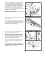
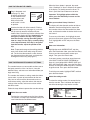
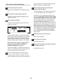
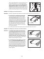
2. Insert the Right Upright (74) into the indicated bracket on
the Base (83); be careful not to dislodge the Cage
Nuts (76) from the Right Upright (see the inset drawing). In addition, be careful not to pinch the Upright
Wire Harness (75). Finger tighten three Upright Bolts
(72) with three Washers (78) and three Upright Star
Washers (71) into the Right Upright and the bracket. Do
not tighten the Upright Bolts yet.
2
75
74
71
78
72
Repeat this step with the Left Upright (not shown). Note:
There is not a wire on the left side.
76
71
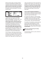
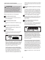
3. Attach the Catch (5) to the left side of the Frame (48) with
two 3/4” Screws (4).
78 72
83
Bracket
3
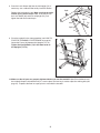
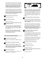
With the help of a second person, raise the Frame (48) to
a vertical position. Be careful not to raise the Frame
past the vertical position. Have the other person hold
the Frame until step 5 is completed.
5
4
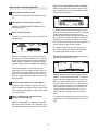
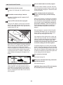
4. Hold the cylinder end of the Gas Spring (88) near the
bracket in the center of the Frame (48).
4
Cylinder
See the two small inset drawings. Using your fingernail
or the end of a screwdriver, press on the end of the
Spring Pin (102) to loosen it from the Gas Spring (88).
Next, rotate the Spring Pin and pull it out of the Shock.
Be careful to avoid losing the Spring Pin.
Orient the Gas Spring (88) so it is in the position shown.
Press the end of the Gas Spring onto the ball on the
bracket.
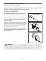
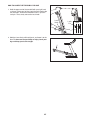
See drawing 4a. Insert the Spring Pin (102) into the two
indicated small holes in the end of the Gas Spring (88).
Then, rotate the Spring Pin until it clips onto the Shock.
Note: Extra Spring Pins are included.
102
48
88
Bracket
102
102
4a
88
102
Hole
Bracket
Hole
7
48