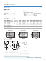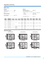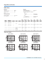
1
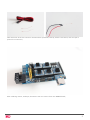
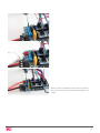
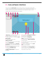
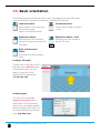
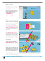
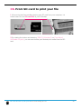
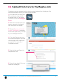
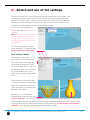
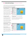
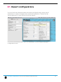
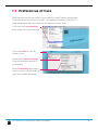
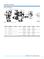
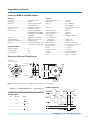
ANEXOS
TÍTULO: Rediseño y fabricación de una impresora 3D RepRap.
AUTOR: Joan Huertas González
TITULACIÓN: Grado en Ingeniería de Diseño industrial y Desarrollo de
Producto.
PONENTE: Juan José Aliau Pons
DEPARTAMENTO: 717, Expresión Gráfica en la Ingeniería
FECHA: 2 de julio de 2014
RAMPS 1.4 WIRING
G3D MANUAL V1.0
25.07.2013
WWW.GADGETS3D.COM
WWW.GADGETS3D.EU
2
RAMPS 1.4
Unpack RAMPS box (RAMPS 1.4 + arduino + sd shield);
3
Take motor wires and solder the same colors from wires with connector and use tape to protect the connection,
this will apply to X, Y and E motors;
connector wires
black
green
red
blue
motor wires
yellow
blue
red
green
4
Take thermistor wires with connector and thermistor (heatbed, hotend), Solder it like before, and use tape to
protect the connection;
After soldering motors, endstops, thermistors You can connect them into RAMPS board;
5
Take endstop connector and place it;
Thermistor connectors should go near endstop pins;
6
Take motor connector and connect it near drivers;
Take flat screwdriver to loose power connector then connect power wires;
7
With the same screwdriver loose hotend connector
then connect wires, after this operation tighten the
screws;
8
RAMPS 1.4 wiring schematic;
9
Additional RAMPS disassembly
Use flat screwdriver to undermine the A4988 step
motor drivers,
10
Use the same tool to deatach arduino module from RAMPS, after this unplug power socket;
11
Now your RAMPS is fully disassembled.
12
Cura 13.11.2
Ultimaker’s software for making 3D prints
User manual
English Version 1.0
Table of Contents
A.
Welcome to Cura
A1. Cura for your Ultimaker
A2. Latest upgrade and fixes
B.
Installing and configuring Cura
B1. Compatible systems
B2. Downloading and installing Cura
B3. Configuration wizard Ultimaker
B4. Continue the wizard for Ultimaker Original
B5. Configuration wizard other 3D printers
7
8
9
10
11
12
C.
First time starting up Cura
C1. Cura software interface
C2. Print with quick print profile
C3. Basic orientation
C4. Adjusting your model
C5. Where Ultimaker 2 and Ultimaker Original differ in Cura
C6. From SD-card to print your file
13
14
15
16
17
19
20
D.
YouMagine.com and sharing with Cura
D1. From YouMagine to load file in Cura
D2. Upload from Cura to YouMagine.com
21
22
23
E.
The
E1.
E2.
E3.
E4. E5.
E6. E7. 25
26
28
29
30
31
32
34
F.
Updating Cura
F1.
Updating Cura
F2. Updating firmware of your Ultimaker
F3. Add a new 3D printer (machine)
F4. Preferences of Cura
F5. Copy profile to clipboard
use of full settings and dual extrusion
Switch and use of full settings
Advanced settings
Extra full settings Ultimaker Original
Cura plugins
Start/End-GCode for Ultimaker Original
Dual extrusion for Ultimaker Original
Expert configurations
Table of content User manual
4
5
6
35
36
37
38
39
40
WELCOME TO
CURA
4
A1.Cura for your Ultimaker
The preferred software for your Ultimaker is Cura. This
software package prepares your 3D model into instructions
that your 3D printer requires to produce an object.
Cura is developed by Ultimaker to make 3D printing as easy
and streamlined as possible. It contains everything you need
to prepare a 3D file for printing. It is fully preconfigured to
work on every Ultimaker model. Cura comes with a friendly
setup program that helps you install the latest firmware as
well as to calibrate your printer.
While you make decisions on the look and quality of your 3D
object, Cura’s slicer engine prepares your model in the background faster than ever. From there It is just seconds away
from your printer and ready to become your physical object.
With the Ultimaker 2 and Cura it’s only possible to copy your
print file to an SD card and print from it. The USB port on your
Ultimaker 2 can be used for firmware updates and in the near
future this gives a possibility for wireless printing. The USB
cable that came with your Ultimaker 2 should only be used for
firmware updates.
With the Ultimaker Original it is possible to print with USB
cable, but we do not advice you to do that. It is less reliable
and other processes on your computer influence the speed of
printing. When available printing with the Ulticontroller is recommended.
A1. Cura for you Ultimaker. Welcome to Cura
5
A2. Latest upgrades and fixes
Almost every month we do a software update where we introduce new
functionalities and improvements.
In the latest Cura 13.11.2
* Adjusted the gantry height to 55mm for the Ultimaker, as 60mm was 3mm to high for the default setup with an V2 hot-end in the Ultimaker Original.
* Added no-go zones for Ultimaker 2 glass clips, to prevent damage to the nozzles on the Ultimaker 2.
* Added ooze-shield for dual-color printing
* Added wipe tower for dual-extrusion
* Made sure the Ultimaker Original bed leveling wizard can not be used on the Ultimaker 2, as this causes problems.
Ultimaker 2 Firmware update version: 13.11-2
* Fixed Ultimaker 2 build volume offset so that you do not print off the glass plate.
* Slightly tweaked the filament change procedure so there is less chance of a blob staying behind.
* Slightly tweaked the SD-Card error problems, solving a rare case of
SD-Card read errors.
* Added LED settings to Tune menu, so you can tune down the LED
lighting during printing.
* Start heating the nozzles when the bed is nearing its final temperature, so the nozzles do not sit hot.
* Make sure all commands are finished before starting a print or changing
material. This could cause issues when you where too fast.
A2. Latest upgrades and fixes. Welcome to Cura
6
INSTALLING AND
CONFIGURING
CURA
7
B1.Compatible systems
Cura will run on the platforms listed below.
- Windows XP or newer
- Mac 10.6 (snow leopard) or newer
- Unix Ubuntu 12.10 or newer
Minimum required hardware
- Minimum of 512 MB of RAM
- Minimum of 200 MB of disk space
- Minimum a pentium 4 processor
Recommended hardware
- 2 GigaByte of RAM
- 500MB disk space
- Intel Core 2 - 2.0Ghz
Compatible file types
.STL
This file format is supported by almost any 3D software package and is the
industry standard used for 3D printing
.OBJ
.DAE
.AMG
B1. Compatible systems. Installing and configuring Cura
8
B2.Downloading and installing Cura
The preferred software for your Ultimaker is Cura from Ultimaker. This software
package prepares your 3D model into instructions that your Ultimaker 2 requires
to produce an object.
1. The Cura software package can be downloaded from the “Our software”
section on our website www.ultimaker.com.
(direct link: www.ultimaker.com/pages/our-software)
2. Download the latest version of Cura for your operating system.
3. Open the installer and follow the directions to install the software.
4. After installing Cura, Start up Cura
and go to the next page to configure
the software to your 3D printer.
NOTE: On every kind of operating system the
installation procedure of the software will work quite
differently.
B2. Downloading and installing Cura. Installing and configuring Cura
9
B3.Configuration wizard Ultimaker
1. Cura welcomes you first with the note: ”This wizard will help you in setting up
Cura for your machine” click [Next >] button to continue.
2. Then you get the
following screen were you
should select what kind of
Ultimaker or other 3D printer
you have.
Cura 13.02 or newer can collect user statistics. These statistics are gathered to
improve next version of Cura and possibly provide more features for Ultimaker
and RepRap users. The collected information includes profile settings and machine
types.
It does NOT collect usernames, models or any privacy sensitive information. Currently these stats are only collected and there is nothing done with it yet. We want
to make these stats quite open for everyone to use as well as the option to share
this information or not.
3. So please check or uncheck the box if you like to share the information or not.
4. If you selected the Ultimaker 2 no additional setup is need and you should seen
the following screen (image below). If you selected the Ultimaker Original you
should follow the instructions on the next page (B4). If you selected anything else
in this configuration wizard continue to page 12 (B5).
B3. Configuration wizard Ultimaker. Installing and configuring Cura
10
B4.Continue wizard for Ultimaker Original
When you selected the Ultimaker Original (the wooden lasercut version) you
need to check the ‘upgrades’ you have or don’t have on your Printer.
5. Follow the Instructions on
the screen and make sure you
select what came with or is
upgraded on your Printer.
The default selection is
suitable for a new Ultimaker
Original.
6. If you are not sure you have
the latest firmware make sure
you choose; Upgrade to Marlin Firmware.
Make sure that the USB
cable is connected.
7. Cura likes to do a checkup
on you machine, with the USB
cable connected you can Run
checks.
You can also skip the checks
if you know your machine is
functional.
8. With USB cable still
connected, the printhead in
your Ultimaker will move itself
to each corner and at the
same time cura will ask you to
adjust the height of the bed.
9. When you finished this step you should arrive on to Cura’s main screen as
shown in step 4.
B3. Configuration wizard Ultimaker Original. Installing and configuring Cura
11
B5.Configuration wizard other 3D printers
When you selected the Other on machine selection, you see a list of other pre- defined machines though if you want to work with them, you might need to tweak
them to get to their best performance.
You also have to set up a custom profile where tinkering and some hardware
knowledge of your 3D printer is required. More about working with custom profiles
in chapter E starting at page 26.
B2. Configuration wizard other 3D printers. Installing and configuring Cura
12
FIRST TIME
STARTING UP
CURA
13
C1.Cura software interface
This is the main ’quick print’ screen of Cura. Here you can load and adjust 3D
models, choose print profiles and upload files to the YouMagine library. Below you
can see a quick overview about all the items in the interface. Later on in this
chapter they will be explained in more depth
1
2
3
4
5
6
8
9
10
1. Menu bar In this bar you can change
settings, machines and profiles.
2. Make a selection in 3 different quick
print profiles.
3. The option to print with
support structure.
4. A button which gives you the opportunity to load objects.
5. With this button you can save prepared files to your Ultimaker SD-card.
6. Through this button you can share
3D files on YouMagine.com.
7. A prepared model can be
viewed in other modes to check it’s
printpath.
7
11
12
13
8. The option to change the rotation of
the object you like to print.
9. The option to change the
Scale of the object you like to print.
10. The options to Mirror the model
you like to print.
11. The model you have loaded through
the load file button.
12. This is a visualisation of the print
area of your Ultimaker.
13. (ultimaker 2) The grey squares in
the build area are the no go zones. In
your Ultimaker 2 these are the metal
clips were you can’t print.
C1. Cura software interace First time starting up Cura
14
C2. Print with quick print profile
Before going into this step, make sure you have a working printer, if not please
calibrate your printer. Need help? check the user manual of the Ultimaker 2 or
Ultimaker Original on our support page.
1. Let’s start by clicking on the Load button in
Cura and search for a compatible file.
2. You might notice the progress bar, when you
have loaded a file into Cura, cura is automatically
making the 3D model print ready for you.
3. In the meantime you can adjust settings and
select a print type.
- High quality prints with layers of 0.06 mm
- Normal quality prints with layers of 0.1 mm
- Low quality prints with layers of 0.2 mm
4. When the 3D model is prepared, the Save
toolpath button shows up and gives you the
option to save the prepared model in a
directory.
Underneath the button Cura gives you an
indication about your print on
- Estimated Print Time
- Amount of material required
- And the weight of your 3D print
5. After you inserted the included SD-card into
your computer, Cura changes the Save toolpath
Button into the Toolpath to SD Button.
SD
6. Just after you choose for the Toolpath to SD
button you will see the same progress bar but
now it saves the file on the SD card.
7. When finished saving It will give you the
notification that your file has been saved.
8. Before taking out the SD-card make sure you
always choose the safely eject button in Cura.
C5. Print with quick print profile First time starting up Cura
15
C3. Basic orientation
The following mouse actions are used to work, navigate and view the 3D model.
You can use those orientation movements in the blue 3D interface.
Scrollwheel button
Use the scroll wheel to zoom in
or out.
Leftmouse button
Select objects. Hold and move
the mouse to drag
object on the 3D print area.
Rightmouse button
Hold and move the mouse to
rotate the viewpoint around the
3D model.
+
Rightmouse button + Shift
Hold and move the mouse to
pan the 3D view
shift
Right and left mouse
button
Hold and move the mouse to
zoom
Loading a 3D model
The left icon on the top of the 3D
interface is the Load file button.
Through this button you can
search in your files to the
following 3D file extensions:
.stl .obj .dae .amf
Loading images
In Cura you can also load
images and convert them to
a 3D model. In the converting
settings you can choose several
option to shape a 3D model. You
can load the following file extentions; .jpg .bmp .png.
C3. Basic orientation First time starting up Cura
16
C4.Adjusting your model
When you have loaded your model you can change the size or orientation, the
following steps explain you the basic on how you can adjust you model on how
you want it to be.
Rotating your object
The left icon on the bottom of
the 3D interface is the rotation
button [1]. When you select and
click it, you can rotate the model
over it’s XYZ axis. You see also
more functions when you have
selected the rotation button.
3
the top icon’s action, lays your
model flat [3] on the surface,
2
to make sure your model is well
1
attached to the build plate while
printing.The second icon resets [2] the 3D models rotation. By click-select one
of the 3 orientation circles you adjust the rotation of the model. The rotation
degree appears in the number around the model. When rotating and clicking shift
you rotate per degree otherwise it’s per 15 degrees.
Scaling your object
The second left icon on the
bottom of the 3D interface is the
scaling button [1]. When you
select and click it, you can scale
the model in the XYZ direction.
The top icon that appears has
the function to scale your object
to max size [3] for your printer.
The icon above resets [2] the 3D
models rotation.
By unlocking [4] the lock you
have the possiblity to scale the
object in each particular
dimension.
3
2
1
4
By select and slide one of the 3 scaling squares
you adjust the uniform scale of the model. The
amount of scaling and size dimensions appears in the number next to the model.
C4. Adjusting your model First time starting up Cura
17
Mirror your object
The third left icon on the bottom
of the 3D interface is the mirror
button [1]. When you select on
the mirroring functions you can
flip you model with the other
buttons above [1] in the:
- X dimension [2]
- Y dimension [3]
- Z dimension [4]
4
3
2
1
Right mouse click on your model.
When you select your model and
give a right mouse click on it you
get some more functions.
With Delete object [1] [5] you
remove your model(s) from cura.
Center on platform [2] positions
your model in the center of the
build plate.
With multiply object [3] you
can decide to make more of the
selected object. If you number is
to much for the amount of space
on your build volume cura will
place it automatically it on maximum quantity.
1
2
3
4
5
3
There is also a function Split
object into parts [4], This function is used to split an model file
which contains multiple parts
4
into separate parts to be printed
one at a time. For example, if you
downloaded an STL file that contains 4 parts of a puzzle, you can
split it into 4 separate parts for
printing. For now it works very
slowly and you might need some patience to split objects, for now we advice your to split
parts in your 3D design program.
C4. Adjusting your model First time starting up Cura
18
C5.Were Ultimaker 2 and Ultimaker Original differ in Cura
With the development of the Ultimaker 2 we decided that the print should know
what kind of material it has. That’s why when you insert material in your
Ultimaker 2 that you also should tell what material it is going to use. The printer
adjust its settings to the material requirements, in this way printfiles (gcode’s)
became material independent and can be easier shared with others. That why you
also had to make a decision earlier in the configuration. There is also a slight difference in the Cura interface and user flow which we will explain on this page.
Ultimaker 2
You can recognize and see that
you have configured Cura to
Ultimaker 2 if the print bed in the
visual interface shows the
Ultimaker 2 logo.
Ultimaker Original
You can see the difference in the
logo in the blue area.
More imporantly you can find
this back in it’s material
functionality. Where Cura asks
you the which material you are
going to use and what thickness
it has.
You will see more functions in
those materials when you put
Cura in Full settings (chapter E).
Note: most of the images being used are setup for the Ultimaker 2, so keep in
mind that the images in this manual may not be the same as the one in your
Interface. We will mention where you need to do take some extra action or where
it differs.
C2. Were Ultimaker 2 and Ultimaker Original differ in Cura First time starting up Cura
19
C6. From SD-card to print your file
1. After saving the file and safely ejecting your SD-card from your computer, it is
time to insert it in the SD-card Slot of your Ultimaker.
Ultimaker 2
Ultimaker Original
2. By rotating the button and selecting [PRINT] (Ultimaker 2) or [Card Menu]
(Ultimaker Original), you can now choose your desired print model from the SDcard.
C6. From SD-card to print your file First time starting up Cura
20
YouMagine.com
and sharing with
CURA
21
D1. From YouMagine to load file in Cura
Now that you are familiar with Cura we continue to explain how you can download
a 3D file from YouMagine and load this into Cura. YouMagine is an online
community for everyone who’s eager to explore the World of 3D printing. Want
to work with other users and learn from each other? Go right ahead: YouMagine
is about sharing and collaboration. Needless to say, everything you upload will
remain your intellectual property which we encourage you to share.
1. Open your browser and go to
www.youmagine.com
2. Use the search field at the
menu bar next to the magnifying
glass to find a model of your
interest. Let’s search for example
“coffee cup” and ‘Enter’.
3. Choose a design you like.
4. The following page will provide you with a ‘Download’ button
where you can get your .stl file
which can be used to print a 3D
model.
5. The .stl file can be loaded into
the Cura software, which will be
explained more fully in the next
chapter.
Tip: If you’ve made a 3D design
yourself, you can contribute back
to the YouMagine community,
this is explained in the next step.
NOTE: The screenshots may not look and work
exactly the same because YouMagine is in
continuous development.
D1. From YouMagine to load file Cura YouMagine and sharing with Cura
22
D2. Upload from Cura to YouMagine.com
Cura also gives you an opportunity to directly upload and easily to YouMagine. We
would like to explain this to you in the following steps.
1. First make sure you have your
3D model that you would like
to upload. Open in Cura, there
you have to click the YouMagine
button.
2. While this is the first time you
want to upload to YouMagine,
this will be your first screen.
3. Choose [Request authorization from YouMagine], your browser will now open and try to login
to your YouMagine account
4. If you don’t have an account
or you are not logged in you see
the following screen. Make sure
you register or log in with a
YouMagine account.
5. Copy the Key and Paste it in
the popup in Cura.
6. Cura will now check if it is connected to YouMagine.
D2. Upload from Cura to Youmagine.com YouMagine and sharing with Cura
23
7. Now you see a screen where
you can put information about
your design, try fill in the entire form, then click the [Share!]
button.
8. When you are logged in you
will see the following screen
which gives Cura acces to your
YouMagine account.
9. From now on, Cura will allow
you to automatically upload your
latest designs to YouMagine.
D2. Upload from Cura to YouMagine.com YouMagine and sharing with Cura
24
THE USE OF
FULL SETTINGS
AND
DUAL EXTRUSION
25
E1. Switch and use of full settings
With Cura we aim for a very simple and friendly experience for our users. The
more experienced you become with 3D printing and our software the more
specific you might want to work in the production of a 3D print. More specific
settings can al be managed through a full setting function we included in the
software. We will explain you this in the following steps.
1. First go in the menu bar to
Expert and select Switch to Full
settings.
Note: When your Cura is configured to
Ultimaker Original you have a fourth
tab, start/end-Gcode, were you can
change the begin and end process of
your printfiles.
2. You can see that you have
more features in 3 different tabs:
Basic, Advanced and Plugins.
Basic settings: Quality
The height of each layer [1]. For
print quality and printing time
this is the most important setting. Usual settings are 0.2mm
for a low quality print. 0.1mm for
a medium quality print. 0.06mm
for a high quality print. And
0.02mm for an ultra-high quality
print.
The thickness of the side shells
[2], when printing a simple cube,
this is the thickness of the side
walls. Increasing it improves the
strength of the part.
1
2
3
Model from YouMagine
Fruit bowl by NachoKaoS
Model from YouMagine
Vase by Marrit
Retraction [3] is pulling the
filament back when moving over
a gap in the print. This reduces the amount of thin lines between printed parts. These thin
lines are called strings. Retraction is usually always enabled, unless you want to print faster
or are printing with a material that does not allow retraction. Some models don’t require
retraction, this vase for example, because there are no gaps.
E1. Upload from Cura to YouMagine.com. The use of full settings and dual extrusion
26
Basic settings: Fill
The bottom/top thickness [1] is
the outer shell thickness on the
top and bottom. For example,
when printing a simple cube, this 1
2
is the bottom square and top
3
square thickness that are put
down. Increasing this will make
a stronger part, and depending
on your model, it will make for
better solid tops.
Cura fills [2] the internal parts of your model with a structure. This grid is made for
strength and to support the top layers. The amount of infill you want is influenced
by this setting. More infill produces stronger parts that take longer to print. If
strength is not a requirement then this setting could be put on 5% for a low density infill that can still support the upper layers.
Basic settings: Print speed [3]
Print speed sets the speed at which the print is put down. The default of 50mm
per second is a bit low for an Ultimaker. But this is a safe starting point. People
have printed up to speeds of 120mm per second. But this requires a well calibrated
and tuned machine.
Basic settings: Support
Supports are structures printed
Model from YouMagine
Vase by Marrit
below the print object to
support parts that otherwise
would be unprintable. There are
2 options, support structures
[4] that need to touch the build 4
platform, or support structures 5
that can also touch the top of
your model.
The platform adhesion type [5]
is a setting to help the printed object stick on the printer bed. Large flat objects
might get lose from the printer bed because of an effect called warping
(curled up corners in the print). There is the option to use a raft, which is a thick
grid under the object which scars the bottom of your print. Or a brim, which are
lines around the bottom of your object and because of the larger area the corners
are kept down. Brim usually gives the best results as it does not scar the object.
But it requires more space on the printer bed.
E1. Upload from Cura to YouMagine.com. The use of full settings and dual extrusion
27
E2. Advanced settings
Advanced settings are settings you usually only change once because you have
special needs that do not match the defaults.
Nozzle size [1] : The size of the
hole in your nozzle. The Ultimaker comes with a 0.4mm nozzle
by default. Some people drill the
nozzle to 0.6 or 0.8mm for faster
printing at lower quality.
1
2
3
4
5
6
7
8
Initial layer thickness [2] : The
thickness of the first layer. This
first layer is set by 0.3mm by default. A 0.3mm layer gives a thick
bottom layer which is easy to
stick to the platform and allows
for variation in the platform.
Bottom layer speed [5]: The speed at which
the print head moves while it is laying down the
first layer. This is done to make the print stick
easier.
Cut off bottom [3] : Cut the bottom of the model, this effectively
sinks the object into the printer
bed. If your object does not
have a lot of contact area with
the printer bed then this feature
could help you.
Infill Speed [6]: The speed at which infill lines
are printed. If set to zero then same speed is
used as for the rest of the print. A slight loss in
outer quality can be expected if you use this
to print a fast infill due to changes in nozzle
pressure when switching between outside and
infill parts.
Travel speed [4]: The speed
at which the printhead moves
when it is not printing. The
default is set on 150mm/s. But
a well calibrated and oiled Ultimaker can go faster and up to
300mm/s. It is not uncommon
for a printer to achieve 200mm/s
or 250mm/s travel speed. But
if you are seeing shifts in your
print then the travel speed might
be the cause.
Minimal layer time [7]: The minimal time spend
on printing a single layer. If a layer takes less
time to print then this configured time, then the
layer is slowed down. This ensures that a layer
is cooled down and solid enough before the
next one is put on top.
Enable cooling fan [8]: The cooling fan is usually enabled and greatly improves print quality
for PLA. For some other materials you might
not want to use the cooling fan at all and this
setting will disable it.
E2. Advanced settings. The use of full settings and dual extrusion
28
E3. Extra full settings Ultimaker Original
As earlier mentioned, with the Ultimaker Original selected in Cura you have some extra
functions that you can tune. With these settings you can take control on the material temperature and the diameter and flow of the filament.
Basic settings: Print temperature and Filament
The print temperature [1] : is the
temperature at which you print.
This setting has a lot of impact
on the print. The default is set
on 220C, which is a bit high for
1
PLA. For PLA you can go down
to 190C to reduce the amount
of strings on the print. But if you 23
want to print faster you might
need to increase the temperatufilament has an average of 2.89mm thickness.
re above the 220 degree.
The filament diameter [2] : is
the diameter of your filament.
Accurate measurement of your
filament gives better quality
prints. This needs to be known
up to 2 decimals. Using digital
calipers to measure you filament
improves results. Ultimaker
The filament flow [3] : is a correction factor
to make extrusion higher or lower then usual.
Some systems or materials require a correction
next to the usual diameter setting. This flow
adjustment can be used for this.
Advanced settings: Retraction
Retraction speed [4] : The speed
at which the filament is pulled
back when the printerhead
needs to move over holes.
Retraction distance [5]: The
amount of mm the filament is
pulled back when a retraction
happens. 4.5mm gives good
results on almost all Ultimakers
with PLA. Other materials might
need different retraction settings.
4
5
Note: At the Ultimaker 2 this is a fine tuned setting that
you don’t need to tune in Cura.
E3. Extra full settings Ultimaker Original. The use of full settings and dual extrusion
29
E4. Cura plugins
Since Cura version 12.11 there is support for plugins. This enables people to easily
include their own features, without having to modify the source code of Cura or
the slicer. Plugins are unavailable in quick print mode, you need to have some
experience. If you want to use it, click on the [Full Settings] mode under [expert] in
the menu bar at the top.
Check this link/button for the plugins:
http://wiki.ultimaker.com/Category:CuraPlugin
In the screenshot above you see a list of plugins (e.g. Skew, Tweak at Z and Wave).
These can be enabled by clicking on the arrow down button. The plugin will appear in the Enabled plugins box. There you can configure the plugin.
Check on this link for how to write a plugin:
http://wiki.ultimaker.com/How_to_write_a_Cura_plug i n
E4. Cura plugins. The use of full settings and dual extrusion
30
E5. Start/End-GCode for Ultimaker Original
What is Gcode
GCode is the generic name for a control language for CNC (or Reprap) machines.
It is a way for you to tell the machine to move to various points at a desired speed,
control the spindle speed, turn on and off various coolants, and all sorts of other
things. It is fairly standard, and is a useful tool.
More about G-code: http://replicat.org/primer
Start/End-Gcode
The start and end gcode are the startup and end procedure of the print. These
pieces of code influence the startup procedure and can be customized. By default
the printer is heated up, homed to the corner, and the head is primed. Editing this
requires knowledge of GCode.
E5. Start/End-Gcode for Ultimaker Original. The use of full settings and dual extrusion
31
E6. Dual extrusion for Ultimaker Original
The dual extrusion KIT is still experimental, which means tinkering for the best
result is needed. At the moment our slicer Cura does not support features recommended for PVA, like ‘wipe’. However, you can experiment with PVA in the dual
extrusion KIT by using another slicer program that does support it. Printing in dual
color is supported.Assembly manual can be found here.
http://wiki.ultimaker.com/Dual_Extrusion
When you are finished with installing the hardware part there are a couple of
steps in the software Cura that need to be taken off before you can really start
printing with your dual extrusion kit.
1. start Cura, go to File > Preferences and set the ‘Extruder
count’ on 2. You might have to
restart Cura before it will actually
take this setting.
2. Next, change the setting in the
Preferences panel to the ones
shown below (click the picture to
enlarge).
If your Dual extrusion is built
perfectly, the offsets should be
X= 0.0 and Y= 21.6 However this
being a DIY Kit, make sure you
play with the settings until your
second material sticks nicely
icely to your first material.
3. In the advanced tab you can
find a setting called Dual Extrusion Overlap, this has default
setting of 0.2 mm. With this
setting you can control how
much the colors should overlap.
This assures a good connection
in between two materials.
Now the settings in Cura are
done and you can start preparing your first dual extrusion
print!
E6. Dual extrusion for Ultimaker Original. The use of full settings and dual extrusion
32
4.Load the 2 models you want to
use for your print, either simultaneously or alternating. They
will both be placed on the build
platform.
5. If you click on the model and
right-mouse click the second
model you get the option: dual
extrusion merge. This will merge
both models into one model for
printing.
6. The model will be dual colored; in this case yellow equals
hot end 1 and red equals hot
end 2, since this is what is set in
the Preferences panel. You can
change the configuration by the
order in which you click during
the merge.
Now you’ve taken all the steps
and are ready to start printing
with your new dual extrusion kit!
If you have created some nice
dual extrusion print models feel
free to share them on our platform YouMagine, as we are very
curious to see what great stuff
you will create!
Cura13.11.2 included new function
for dual extrusion, wipetower
and ooze shield. Wipetower is
a small tower next to your print
where the nozzle wipes itself
clean when switching nozzles.
The ooze shield does the same
and improves this function but
with some models you don’t
want it because you can’t break
it away.
Know that both functions downgrade the printspeed.
E6. Dual extrusion for Ultimaker Original. The use of full settings and dual extrusion
33
E7. Expert configurations
You can check the information about the expert configurations by going over all
the features. A tooltip will appear with some small explanation. The part will be
further explained in a next version of the User manual.
You can use the shortcut key CTRL+E or Command-E (OSX) to open the expert
configuration menu.
E7. Expert configurations. The use of full settings and dual extrusion
34
MACHINE
SETTINGS
AND
UPDATES
35
F1. Updating Cura
Our R&D team is continue improving and updating Cura. We always aim to make
the software more user friendly and simultaneously with new function all in order
to make better and more succesfull 3D prints. Almost every month we update the
software and as a user of Cura you will get a notification of that.
1. If you startup Cura and it gives
the following notification select
Yes to update. Your browser will
open a link to the latest software
and starts downloading right
away.
2. When you finished the installation wizard and start up Cura, it
takes over the machine settings
you had but with improved and
new functionalities of the latest
Cura version.
F1. Updating Cura. Machine settings and Updates
36
F2. Updating firmware of your Ultimaker
With the development of the Ultimaker Original we knew that the hardware was
very reliable and could print with a very high resolution. Besides that it still took
the team a few months to finetune the control of the electronic components in
combination with smarter software. The same applies for the Ultimaker 2 as we
keep on tuning settings the machine will become even better in the future. When
there is a new firmware version this will be communicated throught a blogpost or
you will get a notification in Cura.
1. When their will be new version
you can find this function install
default firmware under Machine
in the Menu bar.
2. Install default firmware or look
up the latest obtained
firmware file (.hex). Now Cura
will start uploading, this will take
around 15 seconds.
F2. Updating firmware of your Ultimaker. Machine settings and Updates
37
F3. Add a new 3D printer (machine)
For using various 3D printers Cura has a build in function to work with different
Ultimakers or 3D printers. So if you had the Ultimaker Original and now like to add
the latest Ultimaker 2 in Cura in works as follows.
1. Under Machine in the menu
bar you select Add new
machine.
2. Select next on the add new
machine wizard step.
3. Select the machine type you
would like to select.
4. New you can switch by
selecting the right machine,
through machine in the Menu
bar.
5. You can remove a 3D printer
machine by going to File in the
Menubar and select Machine
settings, on the bottom of the
pop up you find the function
Remove Machine.
F3. Add a new 3D printer (machine). Machine settings and Updates
38
F4. Preferences of Cura
Other settings such as the colour of your model (in cura) FIlament settings and
Cura settings are positioned in this part. You especially wanted to reach out to
these preferences when you want to know the price of your print.
1. You can find the preferences
menu under File in the Menu bar.
This is the colour of your 3D
model in Cura.
Under these Filament settings
Cura can calculate the price of
your models.
Other Cura settings that are adviced to use but can be turned of
when you uncheck the boxes.
F4. Preferences of Cura Machine settings and Updates
39
F5. Copy profile to clipboard
Under Tools in the Menu bar you will find the function Copy profile to clipboard.
This function can be used when you would like to send your settings to someone
else. You can paste it in a Text area, like this you can share or send it to support,
the forum or to someone. If you copy does text and go to Cura, will it
automatically ask you to use these settings.
F5. Copy profile to clipboard. Machine settings and Updates
40
Stepper Motors and Encoders
Stepper Motors
• NEMA 17, 23, and 34 sizes
• Up to 1710 oz-in. (12.1 N · m)
holding torque
• 3000 rpm max speed
• 1.8 deg step angle
• Matched with P7000 drives
for high performance
Encoders
• 1000 counts/revolution resolution
• NEMA 23 and 34 motor compatibility
• Low profile 1 in. (25.4 mm) height design
and easy mounting
• Industrial construction
Overview
Specifications Contents
National Instruments offers a complete stepper motion control solution –
including stepper motors, drives, controllers, and software – that is easy
to set up, configure, and program. Stepper motors available from NI offer
high torque, precision, and easy connectivity to stepper motor drives. Due
to their ease of use, simplified control needs, and freedom from expensive
feedback requirements, stepper motors are an excellent solution for
applications such as machine control, manufacturing test, semiconductor
positioning, biomedical machines, and lab automation.
NEMA 17 Motor Specifications ....................................................2
Electrical ....................................................................................2
Industry Standards ....................................................................2
Physical ......................................................................................2
Torque versus Speed Tables ......................................................2
Dimensions and Wiring..............................................................2
NEMA 23 Motor Specifications ....................................................3
Electrical ....................................................................................3
Industry Standards ....................................................................3
Physical ......................................................................................3
Torque versus Speed Tables ......................................................3
Dimensions and Wiring..............................................................4
NEMA 34 Motor Specifications ....................................................5
Electrical ....................................................................................5
Industry Standards ....................................................................5
Physical ......................................................................................5
Torque versus Speed Tables ......................................................5
Dimensions and Wiring..............................................................6
Encoders for NEMA 23 and NEMA 34 Motors..............................7
Electrical ....................................................................................7
Industry Standards ....................................................................7
Physical ......................................................................................7
Dimensions, Wiring, and Timing Diagrams ..............................7
Glossary..........................................................................................8
Hardware
Stepper motors provide very precise, extremely cost-effective motion
control. The 2-phase motors inherently move in small, precise, 1.8 degree
increments at 200 steps/revolution and are brushless and maintenancefree. Stepping action is simple to control and does not require complicated,
expensive feedback devices. National Instruments also offers encoders
matched to the motors for applications where position verification is
required. Stepper motors are available from NI in three different NEMA
sizes and with either a single or a dual shaft. The motors provide optimum
performance and easy connectivity when matched with the P7000 series
stepper drives available from NI.
Stepper Motors and Encoders
Specifications
NEMA 17 Motor
Electrical
Physical
Step angle...........................................
Steps per revolution............................
Angular accuracy ................................
Phases .................................................
Operating temperature .......................
Shaft load (20,000 hours at 1,500 rpm)
Radial..............................................
Axial push .......................................
Axial pull.........................................
1.8 deg
200
±3%
2
Industry Standards
-20 to 40 °C
15 lb (6.8 kg) at shaft center
6 lb (2.7 kg)
15 lb (6.8 kg)
Industrial standards ............................ CE, UR
Sealing standard................................. IP40
RoHS compliance................................ Yes
NI Part
Number
Manufacturer
Part Number
Dual Shaft
780067-01
780068-01
780069-01
780070-01
780071-01
780072-01
CTP10ELF10MAA00
CTP10ELF10MMA00
CTP11ELF11MAA00
CTP11ELF11MMA00
CTP12ELF10MAA00
CTP12ELF10MAA00
–
✓
–
✓
–
✓
Holding
Torque
Amps/Phase oz-in. (N . m)
Drive
P70530
Rotor Inertia
oz-in.-s2
(kg-m2 x10-3)
Phase
Inductance
mH
Phase
Resistance
Ω ±10%
Detent
Torque
oz-in. (N . m)
Thermal
Resistance
°C/watt
Max
Speed
rpm
1.0
43 (0.30)
0.0005 (0.0040)
7.7
5.25
1.98 (0.014)
6.21
3000
1.1
63 (0.44)
0.0008 (0.0050)
11
5.19
2.55 (0.018)
5.44
3000
1.0
80 (0.56)
0.0011 (0.0070)
12
6.51
2.97 (0.021)
4.71
3000
Rated current is per phase, with the motor mounted, and winding temperature rise ∆T = 90 °C.
Resistance is with winding at 20 °C.
Torque versus Speed
780069-01 and 780070-01
Torque versus Speed at 1.1 A
780067-01 and 780068-01
Torque versus Speed at 1.0 A
780071-01 and 780072-01
Torque versus Speed at 1.0 A
Dimensions and Wiring
1.68 in.
(42.67 mm)
MAX
0.790 in. ± 0.020 in.
(20.07 mm ± 0.50 mm)
1.220 in.
(31.0 mm)
4 Lead Motors
Max Length A
0.551 in. ± 0.040 in.
(14.00 mm ± 1.02 mm)
0.08 in.
(2 mm)
Black
Orange
Red Yellow
Ø 0.866 in. (22.00 mm)
0.864 in. (21.95 mm)
Ø 0.1969 in. (5.000 mm)
0.1964 in. (4.988 mm)
4 x UNC #4-40 2B
Thread Depth 0.177 in.
(4.5 mm) Min
NI Part Number
780067-01
780068-01
780069-01
780070-01
780071-01
780072-01
Ø 0.1969 in. (5.000 mm)
0.1964 in. (4.988 mm)
-A-
0.002 in. (0.051mm)
Manufacturer Part Number
CTP10ELF10MAA00
CTP10ELF10MMA00
CTP11ELF11MAA00
CTP11ELF11MMA00
CTP12ELF10MAA00
CTP12ELF10MAA00
Dual Shaft
–
✓
–
✓
–
✓
Dual Shaft
Option Only
12 in. (305 mm) Min
Lead Length
#26 AWG (0.14 mm2)
Phase Color
AOrange
A+
Black
BYellow
B+
Red
Max Length A in. (mm)
Net Weight lb (kg)
1.37 (34.7)
0.441 (0.200)
1.61 (40.9)
0.573 (0.260)
1.92 (48.8)
0.750 (0.340)
BUY ONLINE at ni.com or CALL 800 813 3693 (U.S.)
2
Stepper Motors and Encoders
NEMA 23 Motor
Electrical
Physical
Step angle...........................................
Steps per revolution............................
Angular accuracy ................................
Phases .................................................
Operating temperature .......................
Rated ambient temperature................
Shaft load (20,000 hours at 1,500 rpm)
Radial..............................................
Axial push .......................................
Axial pull.........................................
1.8 deg
200
±3%
2
Industry Standards
Industrial standards ............................ CE, cUR, UR
RoHS compliance................................ Yes
NI Part
Number
Manufacturer
Part Number
Dual Shaft
780073-01
780074-01
780075-01
780076-01
780077-01
780078-01
780079-01
780080-01
780081-01
780082-01
780083-01
780084-01
T21NRLC-LNN-NS-00
T21NRLC-LDN-NS-00
T22NRLC-LNN-NS-00
T22NRLC-LDN-NS-00
T23NRLC-LNN-NS-00
T23NRLC-LDN-NS-00
T21NRLH-LNN-NS-00
T21NRLH-LDN-NS-00
T22NRLG-LNN-NS-00
T22NRLG-LDN-NS00
T23NRLH-LNN-NS00
T23NRLH-LDN-NS00
–
✓
–
✓
–
✓
–
✓
–
✓
–
✓
Drive
P70360
P70530
-20 to 40 °C
40 °C
20 lb (9.1 kg) at shaft center
6 lb (2.7 kg)
50 lb (22.7 kg)
Recommended encoder ...................... 780251-01
Holding
Rotor Inertia
Torque
oz-in.-s2
Amps/Phase oz-in. (N . m) (kg-m2 x10-3)
Phase
Inductance
mH
Phase
Resistance
Ω ±10%
Detent
Torque
oz-in. (N . m)
Thermal
Resistance
°C/watt
Max
Speed
rpm
0.40
180
(1.27)
0.0034
(0.0248)
209
42.9
2.97
(0.021)
4.64
3000
0.46
280
(1.98)
0.0056
(0.0408)
41.4
5.95
(0.042)
3.69
3000
0.67
380
(2.68)
0.0084
(0.0612)
136
23.5
6.94
(0.049)
3.04
3000
2.7
180
(1.27)
0.0034
(0.0248)
4.6
0.85
2.97
(0.021)
4.64
3000
2.5
280
(1.98)
0.0056
(0.0408)
7.1
1.23
5.95
(0.042)
3.69
3000
3.0
380
(2.68)
0.0084
(0.0612)
6.2
1.00
6.94
(0.049)
3.04
3000
209
Torque versus Speed
780073-01 and 780074-01
Torque versus Speed at 0.36 A
780075-01 and 780076-01
Torque versus Speed at 0.40 A
780077-01 and 780078-01
Torque versus Speed at 0.52 A
780079-01 and 780080-01
Torque versus Speed at 2.7 A
780081-01 and 780082-01
Torque versus Speed at 2.5 A
780083-01 and 780084-01
Torque versus Speed at 3.0 A
BUY ONLINE at ni.com or CALL 800 813 3693 (U.S.)
3
Stepper Motors and Encoders
Dimensions and Wiring
0.750 in. ± 0.04 in.
(19.1 mm ± 1.1 mm)
2.24 in.
(56.9 mm) MAX
1.856 in.
(47.14 mm)
4X 1.48 in.
(37.6 mm)
Max Length A
0.81 in. ± 0.02 in.
(20.6 mm ± 0.51 mm)
4 Lead Motors
Black
Orange
0.21 in.
(5.3 mm)
4 MTG Holes
Ø 0.205 in. (5.21 mm)
Red Yellow
Ø 1.500 in. ± 0.002 in.
(38.10 mm ± 0.06 mm)
Ø 0.2500 in. (0.350 mm)
0.2495 in. (6.337 mm)
Ø 0.2500 in. (6.350 mm)
0.2495 in. (6.337 mm)
#4-40
GND Screw
NI Part Number
780073-01
780074-01
780075-01
780076-01
780077-01
780078-01
780079-01
780080-01
780081-01
780082-01
780083-01
780084-01
Dual Shaft Only With
Encoder Mounting
2X #4-40 UNC-2B THRU
ON A Ø 1.812 in. B.C. (46.03 mm)
Manufacturer
Part Number
Dual Shaft
T21NRLC-LNN-NS-00
T21NRLC-LDN-NS-00
T22NRLC-LNN-NS-00
T22NRLC-LDN-NS-00
T23NRLC-LNN-NS-00
T23NRLC-LDN-NS-00
T21NRLH-LNN-NS-00
T21NRLH-LDN-NS-00
T22NRLG-LNN-NS-00
T22NRLG-LDN-NS00
T23NRLH-LNN-NS00
T23NRLH-LDN-NS00
–
✓
–
✓
–
✓
–
✓
–
✓
–
✓
Phase Color
Orange
AA+
Black
BYellow
B+
Red
0.05 in.
(1.3 mm)
12 in. (305 mm) Min
Lead Length
#22 AWG P0.35 (mm2)
Max Length A
in. (mm)
Net Weight
lb (kg)
2.21
(56.1)
1.6
(0.7)
3.06
(77.7)
2.3
(1.0)
4.06
(103.1)
3.2
(1.5)
2.21
(56.1)
1.6
(0.7)
3.06
(77.7)
2.3
(1.0)
4.06
(103.1)
3.2
(1.5)
BUY ONLINE at ni.com or CALL 800 813 3693 (U.S.)
4
Stepper Motors and Encoders
NEMA 34 Motor
Electrical
Physical
Step angle...........................................
Steps per revolution............................
Angular accuracy ................................
Phases .................................................
1.8 deg
200
±3%
2
Operating temperature .......................
Rated ambient temperature................
Shaft load (20,000 hours at 1,500 rpm)
Radial
N31, N32 ....................................
N33 .............................................
Axial
N31, N32, N33 ...........................
Recommended encoder ......................
Industry Standards
Industrial standards ............................ CE, cUR, UR
RoHS compliance................................ Yes
NI Part
Number
Manufacturer
Part Number
Dual Shaft
780085-01
780086-01
780087-01
780088-01
780089-01
780090-01
780091-01
780092-01
780093-01
780094-01
780095-01
780096-01
N31HRLG-LNK-NS-00
N31HRLG-LEK-M2-00
N32HRLG-LNK-NS-00
N32HRLG-LEK-M2-00
N33HRLG-LNK-NS-00
N33HRLG-LEK-M2-00
N31HRHJ-LNK-NS-00
N31HRHJ-LEK-M2-00
N32HRHJ-LNK-NS-00
N32HRHJ-LEK-M2-00
N33HRHJ-LNK-NS-00
N33HRHJ-LEK-M2-00
–
✓
–
✓
–
✓
–
✓
–
✓
–
✓
Drive
P70360
P70530
-20 to 40 °C
40 °C
65 lb (29.5 kg)
110 lb (49.9 kg)
305 lb (138.3 kg)
780252-02
Holding
Rotor Inertia
Torque
oz-in.-s2
Amps/Phase oz-in. (N . m) (kg-m2 x10-3)
Phase
Inductance
mH
Phase
Resistance
Ω ±10%
Detent
Torque
oz-in. (N . m)
Thermal
Resistance
°C/watt
Max
Speed
rpm
0.86
641
(4.52)
0.0202
(0.1430)
138
16.2
18.0
(0.127)
2.65
2400
0.95
1240
(8.76)
0.0380
(0.2680)
206
17.6
36.0
(0.254)
2.00
1800
1.24
1710
(12.08)
0.0567
(0.4000)
144
13.0
54.0
(0.381)
1.61
1800
5.5
645
(4.55)
0.0202
(0.1430)
3.5
0.42
18.0
(0.127)
2.65
3000
5.1
1195
(8.43)
0.0380
(0.2700)
6.5
0.63
36.0
(0.254)
2.00
3000
5.0
1710
(12.07)
0.0567
(0.4000)
9.0
0.83
54.0
(0.381)
1.61
3000
Torque versus Speed
780085-01 and 780086-01
Torque versus Speed at 0.81 A
780087-01 and 780088-01
Torque versus Speed at 0.88 A
780089-01 and 780090-01
Torque versus Speed at 1.24 A
780091-01 and 780092-01
Torque versus Speed at 5 A
780093-01 and 780094-01
Torque versus Speed at 5 A
780095-01 and 780096-01
Torque versus Speed at 5 A
BUY ONLINE at ni.com or CALL 800 813 3693 (U.S.)
5
Stepper Motors and Encoders
Dimensions and Wiring
4X Ø 0.218 in. (5.537 mm) Thru
Equally Spaced On
4X Ø 3.875 in. (98.425 mm) B.C.
0.875 ± 0.010 in.
(22.23 ± 0.254 mm)
Motor Leads
3.38 in.
(85.852 mm)
Dual Shaft
Option Only
4 Lead Motors
2X 45°
C
D
Ø 0.3750
(9.525
B
0.06 in.
(1.52 mm)
1.12 ± 0.06 in.
(28.448 ± 1.520 mm)
0.33 in.
(8.38 mm)
0.002 in.
(0.051 mm)
-A-
Ø 2.875 ± 0.002 in.
(73.025 ± 0.051 mm)
1.25 in.
(31.750 mm)
0.003 in.
(0.077 mm) A
+0.0000
–0.0005 in.
–0.013 mm)
0.002 in.
(0.051 mm)
Max
Length A
Black
Orange
Dual Shaft
Option Only
2X Ø 2-56 UNC-2B
0.20 Min.
ON A Ø 1.812 in. B.C.
(46.025 mm)
0.003 in.
(0.077 mm) A
Red Yellow
Phase Color
AOrange
A+
Black
Yellow
BB+
Red
Note: Motor leads are 12.0 in. (304.8 mm) minimum.
NI Part Number
Manufacturer
Part Number
Dual Shaft
780085-01
780086-01
780087-01
780088-01
780089-01
780090-01
780091-01
780092-01
780093-01
780094-01
780095-01
780096-01
N31HRLG-LNK-NS-00
N31HRLG-LEK-M2-00
N32HRLG-LNK-NS-00
N32HRLG-LEK-M2-00
N33HRLG-LNK-NS-00
N33HRLG-LEK-M2-00
N31HRHJ-LNK-NS-00
N31HRHJ-LEK-M2-00
N32HRHJ-LNK-NS-00
N32HRHJ-LEK-M2-00
N33HRHJ-LNK-NS-00
N33HRHJ-LEK-M2-00
–
✓
–
✓
–
✓
–
✓
–
✓
–
✓
Max Length A
in. (mm)
B
in. (mm)
C
in. (mm)
D
in. (mm)
Net Weight
lb (kg)
3.13 (79.502)
0.5000 (12.700)
0.4995 (12.687)
0.1250 (3.175)
0.1230 (3.124)
0.555 (14.097)
0.538 (13.665)
5.0 (2.27)
4.65 (118.11)
0.5000 (12.700)
0.4995 (12.687)
0.1250 (3.175)
0.1230 (3.124)
0.555 (14.097)
0.538 (13.665)
8.4 (2.27)
6.13 (155.70)
0.6250 (15.875)
0.6245 (15.862)
0.1875 (4.763)
0.1855 (4.712)
0.705 (17.907)
0.688 (17.475)
11.9 (5.39)
BUY ONLINE at ni.com or CALL 800 813 3693 (U.S.)
6
Stepper Motors and Encoders
Encoders for NEMA 23 and NEMA 34 Motors
Electrical
Physical
Resolution ........................................... 1000 counts/revolution
Input voltage ....................................... 5 V ±10%
Input current........................................ 100 mA max (65 mA typical)
with no output load
Channel configuration......................... Quadrature A, B, and Index
Output type ......................................... Differential line driver
Noise immunity................................... Tested to BS EN61000-6-2;
BS EN50081-02; BS EN61000-4-2;
BS EN61000-4-3; BS EN61000-4-6;
BS EN500811
Symmetry ............................................ 180 deg (±18 deg) electrical
Quadrature phasing ............................ 90 deg (±22.5 deg) electrical
Minimum edge separation.................. 67.5 deg electrical
Accuracy.............................................. Within 0.017 deg mechanical or
1 arc-minute from true position
Operating temperature ....................... -20 to 85 °C
Model type.......................................... Thru-bore
Bore size.............................................. 1/4 in. (780251-01),
8 mm (780252-01)
Mounting............................................. 1.812 in. (46 mm) two-hole
flex mount
Maximum frequency ........................... 200 kHz
Operating temperature ....................... 20 to 85 °C
Max shaft speed ................................. 8000 rpm
Bore tolerance..................................... -0.0000 in./+0.0006 in.
User shaft tolerances
Radial runout .................................. 0.008 in. max
Axial endplay .................................. ±0.030 in. max
Starting torque.................................... 0.300 oz-in. (0.212 N . m)
Moment of inertia............................... 6.7 x 10⁻⁵ oz-in.-sec2 (4.8 gm-cm2)
Max acceleration ................................ 1 x 10⁵ rad/sec2
Weight................................................. 3 oz typical
Storage temperature........................... -25 to 85 °C
Humidity .............................................. 98% RH noncondensing
Vibration.............................................. 10 g @ 58 to 500 Hz
Shock................................................... 80 g @ 11 ms duration
Industry Standards
Industrial standards ............................ CE
Sealing standard................................. IP50
RoHS compliance................................ Yes
Dimensions, Wiring, and Timing Diagrams
Cable Length
18 in. (457 mm) Standard
0.07 in. (1.8 mm)
M3 Set Screws 2X 90˚
Ø 2.10 in. Ø 1.811 in.
(53.4 mm) (46.00 mm)
1.00 in. (25.4 mm)
A (Thru-Bore)
Ø 1.5 in.
(38 mm)
15-saflex
Ø 0.125 in. Thru 2X
180˚ for #4 or M3
Mounting Screws
Note: All dimensions have a tolerance of ±0.005 in. or ±0.01 in. unless otherwise specified.
NI Part Number
780251-01
780252-02
Manufacturer Part Number
15T-01SA-1000-N5RHV-F00-CE
15T-14SA-1000-N5RHV-F00-CE
A (Thru-Bore Diameter)
1/4 in., 0.250 in.
8 mm
Quadrature Waveform
Wire Description
Pin #
1
2
3
4
5
6
7
8
Wire Color
Brown
White
Yellow
Red
Green
Orange
Black
Blue
Function
A
+VDC
A
B
B
Z
COM
Z
BUY ONLINE at ni.com or CALL 800 813 3693 (U.S.)
7
Stepper Motors and Encoders
Glossary
amps/phase – The maximum amount of current allowed through a phase of the stepper motor. Holding torque, the speed versus torque curve, and
so on are determined when the motor is excited by this value. The specifications listed in this data sheet are adjusted for the winding configuration.
angular accuracy – A percentage of the step angle that defines the accuracy of each full step.
detent torque (cogging torque) – The amount of torque necessary to rotate the stepper motor one full step when the motor is deenergized.
differential line driver – A type of electrical digital output that can transmit digital data over a long distance. It consists of a complementary
pair of digital lines.
electrical symmetry – How close each quadrature channel is to a 50 percent duty cycle when at a constant speed.
holding torque – The amount of torque necessary to rotate the stepper motor one full step (microstepping turned off) when the motor is
energized at the rated amps/phase of that motor.
minimum edge separation – Defines in degrees how close (electrically) an edge on channel A can be to an edge on channel B.
NEMA – National Electrical Manufacturers Association (NEMA). NEMA is a U.S.-based association that creates standards for mountings.
The NEMA size of a motor defines its shaft size and mounting configuration.
phase inductance – The inductance of each phase of the stepper motor. The specifications listed in this data sheet are already adjusted
for the winding configuration.
phases – A wound wire in the stepper motor that is excited with current to produce electromagnetic force. Two or more phases work
together by alternating between positively energized, deenergized, and negatively energized states to rotate the stepper motor.
quadrature phasing – The electrical phase shift between channels A and B in a quadrature encoder.
step angle – The distance the motor rotates each full step of the stepper motor. Also defined as 360 degrees divided by the steps per revolution.
BUY ONLINE at ni.com or CALL 800 813 3693 (U.S.)
8
IN
TA
PL
AN
MA
IN
NI Services and Support
P
DE
LO
Y
EL
OP
SERVICE
NEEDS
V
DE
NI has the services and support to meet
your needs around the globe and through
the application life cycle – from planning
and development through deployment
and ongoing maintenance. We offer
services and service levels to meet
customer requirements in research,
design, validation, and manufacturing.
Visit ni.com/services.
Training and Certification
NI training is the fastest, most certain route to productivity with our
products. NI training can shorten your learning curve, save development
time, and reduce maintenance costs over the application life cycle. We
schedule instructor-led courses in cities worldwide, or we can hold a
course at your facility. We also offer a professional certification program
that identifies individuals who have high levels of skill and knowledge on
using NI products. Visit ni.com/training.
Professional Services
Our NI Professional Services team is composed of NI applications and
systems engineers and a worldwide National Instruments Alliance Partner
program of more than 600 independent consultants and integrators. Services
range from start-up assistance to
turnkey system integration.
Visit ni.com/alliance.
OEM Support
We offer design-in consulting and product integration assistance if you
want to use our products for OEM applications. For information about
special pricing and services for OEM customers, visit ni.com/oem.
Local Sales and Technical Support
In offices worldwide, our staff is local to the country, giving you access to
engineers who speak your language. NI delivers industry-leading technical
support through online knowledge bases, our applications engineers,
and access to 14,000 measurement and automation professionals within
NI Developer Exchange forums. Find immediate answers to your questions
at ni.com/support.
We also offer service programs that provide automatic upgrades to your
application development environment and higher levels of technical support.
Visit ni.com/ssp.
Hardware Services
System Assurance Programs
NI system assurance programs are designed to make it even easier for you to
own an NI system. These programs include configuration and deployment
services for your NI PXI, CompactRIO, or Compact FieldPoint system. The
NI Basic System Assurance Program provides a simple integration test and
ensures that your system is delivered completely assembled in one box.
When you configure your system with the NI Standard System Assurance
Program, you can select from available NI system driver sets and application
development environments to create customized, reorderable software
configurations. Your system arrives fully assembled and tested in one box with
your software preinstalled. When you order your system with the standard
program, you also receive system-specific documentation including a bill of
materials, an integration test report, a recommended maintenance plan, and
frequently asked question documents. Finally, the standard program reduces
the total cost of owning an NI system by providing three years of warranty
coverage and calibration service. Use the online product advisors at
ni.com/advisor to find a system assurance program to meet your needs.
Calibration Services
NI recognizes the need to maintain properly calibrated devices for highaccuracy measurements. We provide manual calibration procedures, services
to recalibrate your products, and automated calibration software specifically
designed for use by metrology laboratories. Visit ni.com/calibration.
Repair and Extended Warranty
NI provides complete repair services for our products. Express repair
and advance replacement services are also available. We offer
extended warranties to help you meet project life-cycle requirements.
Visit ni.com/services.
ni.com • 800 813 3693
National Instruments • [email protected]
©2009 National Instruments. All rights reserved. CompactRIO, FieldPoint, National Instruments, National Instruments Alliance Partner, NI, and ni.com are trademarks of National Instruments.
Portions of this document are included by permission of Danaher Corporation and are subject to the following copyright notice: "©2007 Danaher Motion™. All rights reserved. Information &
specifications subject to change at any time. All trademarks property of their respective owners." Portions of this document are included by permission of Encoder Products Corporation and are
subject to the following copyright notice: "Copyright © 2002-2007 Encoder Products Co. All rights reserved." Other product and company names listed are trademarks or trade names of their
respective companies. A National Instruments Alliance Partner is a business entity independent from National Instruments and has no agency, partnership, or joint-venture relationship with
National Instruments. 2009-10412-341-101-D