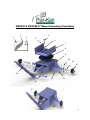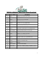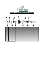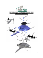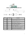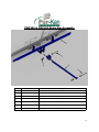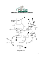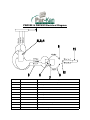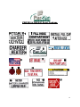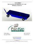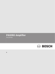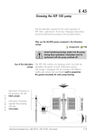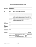
1
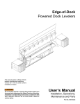
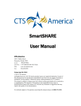
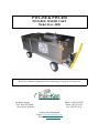
PWC250 & PWC450
POTABLE WATER CART
Model Year: 2008
*** Important ***
Read User’s Manual Completely Prior to Operating, Towing, or Servicing Cart
Par-Kan Company
2915 West 900 South
Silver Lake, IN 46982
Phone: 1-800-291-5487
Phone: 260-352-2141
Fax: 260-352-2141
Contact: Sales Department
Email: GSE [email protected]
Website: www.par-kan.com
PWC250 & PWC450
CUSTOMER: __________________________________
SERIAL # _____________________________________
MANUFACTURING DATE: -_____________________
2
PWC250 & PWC450 Manual Table of Contents
Page 1............................................. Cover Page
Page 2............................................. Unit Information
Page 3............................................. Table of Contents
Page 4............................................. Manual Introduction
Page 5............................................. Warranty Information
Page 6............................................. General Information
Page 7............................................. Operating Instructions
Page 8............................................. Safety Precautions
Page 9............................................. Specifications & Capabilities
Page 10-12...................................... Maintenance & Overhaul
Page 13........................................... Troubleshooting
Page 14........................................... Illustrated Parts Listing
Page 15-17 ..................................... PWC250 & PWC450 5th Wheel Assembly
Page 18-20...................................... PWC450 5th Wheel Torsion Axle Assembly
Page 21........................................... PWC250 & PWC450 Brake Bar Assembly
Page 22-24...................................... Electrical Diagram
Page 25-26...................................... Decal Package
3
PWC250 & PWC450 Manual Introduction
This manual incorporates information for Par-Kan Company’s Potable Water Cart, model
250 & 450 and includes general information, operation, maintenance, overhaul and illustrated parts lists. This manual replaces all Par-Kan Company’s PWC250 & PWC450 manuals previously issued in their entirety.
If errors or misinformation are found, change requests should be submitted in writing to the
manufacturer.
If you have any questions about this product or would like further information about ParKan Company’s ground support equipment please contact the manufacturer at:
Par-Kan Company
Ground Support Equipment Division
P.O. Box 219
2915 West 900 South
Silver Lake, IN 46982
(260) 352-2141
(260) 352-0701 Fax
4
Par-Kan Company – Ground Support Equipment
Model PWC250 & PWC450 Warranty
Par-Kan Company’s Ground Support Equipment is warrantied to the original purchaser to be free from defects in material and workmanship for a period of one year
from the date of purchase as dated on Par-Kan’s original invoice.
Par-Kan will replace during the warranty period, subject to an examination by an authorized representative of Par-Kan, any warrantied part which proves defective in material and/or workmanship under normal installation, use, and service. Parts must be
returned, and transportation charges prepaid to our factory. Any damage to Par-Kan
equipment as a result of modifications, misuse, abuse, neglect, accident, vandalism,
fire, flood, other acts of God, or improper installation will void this warranty.
If Par-Kan receives notice of such defects during the warranty period, Par-Kan will
either, at its option, repair or replace products which prove to be defective. Other
manufacturer’s warranties may apply for parts purchased by Par-Kan. Par-Kan Company makes no other warranty, either expressed or implied, with respect to this product. Any special, incidental, or consequential damages arising from any breach of
warranty are specifically excluded hereunder.
5
PWC250 & PWC450 General Information
Steering:
Ball Bearing Turntable Steering
Wheels:
5 Bolt hub assembly with bearings (1,750 lb. load capacity each )
Removable Spindles: 1-3/4” diameter
Tires: 5.70 x 8.00 Pneumatic
Parking Brakes: Tow bar activated friction brake
Tow Bar:
2-1/2” I.D. Tow bar lunette ring
5 Ton capacity
Finish:
White enamel finish
Reflectors:
3” Diameter (Amber / Red) D.O.T. approved
Location: Front, Rear, and Sides
Cart Design:
Main Frame: Tube – 2” x 2” x 3/16”
Shell: 14ga stainless steel
Tank Design:
PWC 250 Poly Tank
PWC 450 Stainless Steel
Pump:
12 volt electric pump
Options:
25ft fill hose
Winterization Package
Manual Hose Reel
4.8 Honda Engine / Bronze Pedestal Pump
Diaphragm Style Auxiliary Hand Pump
Extended Fill Coupler
Torsion Stub Axles on PWC450 ONLY
3.3 Honda Engine / Bronze Pedestal Pump
Stainless Steel Shell
6
PWC250 & PWC450 Operating Instructions
1. Check to ensure that the unit is unplugged from power source, all hoses are secured, and that all access
doors and hatches are closed.
2. Release the parking brake by pushing the tow bar back towards the unit and lifting up the brake latch
with your foot, the brake will release as the tow bar is lowered into a horizontal position. Do not drop
the tow bar.
3. Lay tow bar in a horizontal position and attach the tow bar to the towing vehicle. The tongue should
be securely attached to the vehicle using all safety devices to ensure that the unit does not disconnect
from the tow vehicle.
4. Tow the unit to the desired location, turn the tow vehicle engine off and set the parking brake. CAUTION: DO NOT EXCEED 15MPH
5. Remove the fill hose from the rear storage compartment. To remove cap from fill coupler grasp cap in
left hand and grasp coupler in right hand. Turn coupler counter-clockwise while turning cap clockwise,
cap will release. CAUTION: POINT COUPLER AWAY FROM BODY WHEN REMOVING CAP,
THE HOSE MAY BE UNDER PRESSURE. Connect the fill hose to the aircraft and open the ball
valve on filler hose. At the rear of the unit reset the meter, start the engine, (Refer to engine manufactures manual for starting procedures) (WARNING: ENGINE ACCESS DOORS MUST BE LEFT
OPEN WHILE ENGINE IS RUNNING) and dispense the desired amount of water. When transfer is
complete turn off engine, and close access doors. Close the ball valve on fill hose and remove from aircraft, replace cap on fill coupler, stow fill hose in compartment. Ensure that all caps are securely installed
on aircraft and that the access panel or panels have been secured. Check to ensure that all hoses have
been disconnected and properly stored, engine is turned off, and that all access doors on unit are closed
prior to moving the unit.
6. Tow the unit to designated parking area, and disconnect the tow bar from the tow vehicle. To activate
the parking brake push tow bar towards unit until tow bar latch locks tow bar in place . When tow bar is
in the vertical position the parking brake is set. Plug the unit back into power source and check indicator
lamp on rear of unit to ensure power is being received.
7
PWC250 & PWC450 Safety Precautions
TOWING:
The PWC250 and PWC450 cart is designed for aircraft ramp use only. It is not intended for highway or off-road use. Towing speed should not exceed 15mph. Always
stow hoses and close all access doors prior to moving unit. CAUTION: NEVER ATTEMPT TO MOVE THE UNIT WHILE HOSES ARE CONNECTED TO THE
AIRCRAFT.
PARKING:
When the unit is parked, tow bar should be latched in the upright position to engage the
parking brake. If unit is not connected to the tow vehicle the parking brake must be
engaged to prevent unit from rolling.
OPERATING:
Before moving unit, ensure the power supply has been disconnected from the outlet.
When moving the unit by hand use caution, especially in wet conditions. The brakes
on the PWC250 & PWC450 depend on friction between the brake bar and tire, wet
conditions will require a greater braking distance. When removing cap from fill coupler point coupler away from body, the hose may be under pressure.
FUELING:
Never fuel service cart while engine is running. Refer to the engine manufacturer owners manual for type of fuel, fueling procedure, and for additional precautionary measures.
SANITATION:
The tank, filter and delivery system should be checked daily for contaminants. Refer to disinfecting system chart for proper decontamination.
8
PWC250 & PWC450 Specifications and Capabilities
PWC250
PWC450
Dimensions:
Length : 96” + 32” Tow Bar
Width: 48”
Height: 48”
Length: 130”
Width: 59”
Height:59”
Empty Weight: (Approx.)
1526 lbs.
1738 lbs.
Tank Capacity:
- Water Tank
946.25 Liters (250 gal.)
1710 Liters (450 gal.)
Pump Flow Rate:
Honda 2.5 hp.
Diaphragm Hand Pump
12 Volt Pump
17 g.p.m.
1 gallon per 5 strokes
7.5 gpm
Speed Limit: Towing speed should not exceed 15 mph.
9
PWC250 & PWC450 Maintenance / Overhaul
Maintenance:
Proper maintenance is an essential part of a long life for the PWC250 & PWC450. As with any equipment the cart needs inspections, lubrications and adjustments to keep it in good condition while providing maximum protection for the equipment.
WARNING: Before removing or installing any components, be sure the trailer is on level ground with
the wheels securely blocked.
Wheels and Tires:
Check the tire pressure weekly. The proper pressure is labeled on the tire.
Check and adjust the wheel bearings during the first few days of operation.
To tighten wheel bearings:
1. Remove dust cap
2. Remove cotter pin from the castle nut and tighten the nut until there is a slight drag on the
bearing while turning the wheel.
3. Loosen the nut one slot and reinsert the cotter pin.
4. Following this adjustment there should be a slight amount of drag on the bearing.
5. Replace the dust cap.
Wheel Bearing Lubrication:
Pack the wheel bearings every 6 months or as needed with S.A.E. multi-purpose grease.
Brake Adjustment:
Periodic adjustment of the brake is needed to assure proper operation.
1. Raise the tongue so that the tongue latch touches the tongue.
2. With the tongue in this position, check the rub brake, the rub brake should just touch the tires.
3. If the rub brake is not properly adjusted, adjust the draglink so that the rub brake touches the
tire. To adjust the draglink loosen the nuts and adjust the threaded rod accordingly, then retighten the nuts against the brake yoke.
Battery:
Maintenance Free
FIFTH WHEEL STEERING
Check the steering assembly daily; ensure that the tow bar pin assembly and cotter pin are securely fastened to the lower fifth wheel box. WARNING: FAILURE TO ENSURE THAT PIN IS SECURED
COULD LEAD TO LOSS OF STEERING AND CONTROL OF THE UNIT.
Storage:
When storing the unit for extended period of time, the following procedures are suggested
1. Touch up all worn or damaged paint
2. Lift and block unit with tires lifted off the ground.
3. Remove battery
4. Drain and rinse tanks
5. Drain meter and hoses
10
PWC250 & PWC450 Maintenance / Overhaul
Disinfecting System
The Potable Water Cart tank and supply system must be properly disinfected prior to being placed
into service. The tank and water supply system of the Potable Water Cart should also be
disinfected when repairs have been made to the tank or supply lines or if there is evidence of
contamination.
The following is an excerpt taken from the U.S. Department of Health Education and Welfare,
Public Health Service, Food and Drug Administration Washington D.C. 20204 PHS Pub. No. 308,
1964 Revision, 1974 Reprint.
The following instructions should be utilized in the disinfection of potable water of potable systems
by the use of chlorine compounds:
A: Flush the tank and distribution system with potable water.
B: Determine the volume of water necessary to fill the tanks and distribution
system completely. The amount of disinfecting agent required may be determined
from table L . When the capacity of the system or the concentration of chlorine in
the compound is different from those listed in the table below, the amount of
disinfecting agent for 50-p.p.m. solution can be computed by:
Dosage of powder =
Dosage of liquid
=
70 %
X dosage in 70 - percent column
Percent chlorine in composition
5%
X dosage in 5 – percent column
Percent chlorine in liquid
Capacity of system
Gallons
Pounds
Chlorinated
Lime
(25 percent)
Ounces of chlorine compound required
High-Test
Liquid Sodium HyCalcium
pochlorite
Hypochlorite
5%
10%
(70 percent)
50
75
100
125
150
175
200
250
417
626
834
1,043
1,251
1,460
1,668
2,085
1.3
2.0
2.7
3.3
4.0
4.7
5.3
6.7
0.5
0.7
1.0
1.2
1.4
1.7
1.9
2.4
6.7
10.
0
13.
3
16.
7
20.
0
23.
3
26.
7
33.
3
3.3
5.0
6.7
8.3
10.0
11.7
13.3
16.7
Table L – Amount of chlorine required for a 50-p.p.m. Solution Continued on next page.
11
PWC250 & PWC450 Maintenance / Overhaul
Preparing Solution
Prepare the chlorine solution as follows:
1. Chlorinated Lime. Place the proper amount of chlorine compound in a clean, dry bucket.
Add a small amount of water and mix to a thick paste. Dilute the paste by adding water gradually and
stirring constantly until the chemical goes into solution. (Warm water is better than cold water for this
purpose.) Allow the solution to stand for 30 minutes so that the undissolved particles may settle to the
bottom. Pour off the clear liquid (which is the chlorine solution) and if necessary, filter it through muslin
or cheesecloth.
2. High-Test Hypochlorite. Place the proper amount in a bucket, fill with water and stir until the powder
is dissolved (disregard slight turbidity, if any).
3. Liquid Sodium Hypochlorite. These solutions require no additional preparation.
A. Introduce the chlorine solution into the potable water tank.
B. Immediately after introducing the chlorine solution the tank should be completely filled with water.
Sufficient mixing usually will be obtained by swirling action of the incoming water.
C. Open each tap on the distribution system and allow the water to flow until chlorinated water appears.
Since a certain amount of the chlorinated water will have been drawn from the storage tank it should be
refilled to overflowing and chlorine solution should be added, if necessary, to obtain at least a 50 p.p.m.
dose in tank.
D. After the tank and the piping system have been filled the chlorinated water should be allowed to stand
in them for at least 4 hours before it is discharged. (In an emergency, the contact time may be shortened
to 1 hour by increasing the dosage to 100 p.p.m.).
12
PWC250 & PWC450 Troubleshooting
If the brakes do not engage or disengage?
Check the brake yoke bar adjustment
If the steering on the unit will not turn?
Check to ensure the brake is not engaged
If the unit pulls to one side?
Check the tire pressure and bearings
If the tow bar will not stay in the locked position
Check the tow bar latch and latch bar for excessive wear
Check the brake yoke bar for any adjustment
If the unit will not pump fluid?
Check the fluid level in tank then check to ensure that all valves are open
Check the fill hose for kinks or blockages
If the engine / hand pump will not pump?
Check the gas tank for fuel
Check the love joy couplings for any damage
Check the pump for compression
If meter does not work properly?
- Check to ensure fluid is being pumped, if fluid is flowing stop pumping and reset meter
13
PWC250 & PWC450 Illustrated Parts Listing
The illustrated parts list contains a breakdown of the PWC250 & PWC450. All parts
contained in the water cart that can be disassembled, repaired, manufactured,
replaced or reassembled are listed.
Each sketched assembly is followed immediately by its detailed parts list.
Item Number Column: The figure and index numbers key the detailed parts list to the
applicable illustration.
Part Number Column: This column contains the manufacturer’s and vendor’s part
numbers.
14
PWC250 & PWC450 5th Wheel Assembly (Fixed Axle)
2
1
4
3
5
6
7
8
9
10
11
12
15
14
13
16
17
18
15
PWC250 & PWC450 5th Wheel Parts Listing (Fixed Axle)
Item No.
Part Number
Description
1
216507
LOCKNUT, 3/8"-16 HEX 2-WAY - ZINC
2
CBC510-2P500
LATCH, TOW BAR
3
211061
HHCS, 3/8"-16 X 1-1/2" GR5 ZINC
4
CBC510-2P600
5TH WHEEL BOLT
5
210104
ROLL PIN, 3/8" X 2-1/2" (SPRING PIN)
6
216220
NUT, 1-1/4"-12 SLOTTED HEX - PLAIN
7
CBC510-2W035
UPPER 5TH WHEEL WELDMENT
8
241197
TURNTABLE, LAMINATED W/3/4" CHROME BALLS
9
CBC510-2W015
LOWER 5TH WHEEL WDMT, FAFP PWC 450
OBC480-2W015
LOWER 5TH WHEEL WDMT, FAFP PWC 250
10
216507
LOCKNUT, 3/8”-16 HEX 2-WAY ZINC
11
241000
SPINDLE, “STANDARD” GSE
12
241025
HUB ASSY., 5 BOLT 4 1/2” “STANDARD” GSE
13
211069
HHCS,3/8”-16 X 3 1/2” GR5 ZINC
14
217003
WASHER, 3/8” USS FLAT ZINC
15
270510
TOWBAR
16
CBC510-2W041
TOW BAR PIN WELDMENT
17
CBC480-2S015
FIXED AXLE, LOWER 5TH WHEEL ASSEMBLY PWC250
18
CBC510-2S015
FIXED AXLE, LOWER 5TH WHEEL ASSEMBLY PWC450
16
PWC250 & PWC450 Spindle & Hub Assembly
Key #
1
2
3
4
5
6
7
8
9
10
11
12
**
Part Number
241108
241107
241109
241106
241105
241104
241103
241025
241102
241101
241100
241000
219023
Description
Cotter Pin
Spindle Nut
Dust Cap
Washer with D shaped hole
Outer Bearing
Outer Cup
Lug Bolt
Hub Assembly ( Includes part numbers 1-11 )
Inner Cup
Inner Bearing
Grease Seal
Spindle
Pack of 20 lug nuts (bolt bag)
** Not included in the illustration
17
PWC450 LOWER 5TH WHEEL TORSION AXLE
ASSEMBLY (BEARING)
4
2
3
5
6
1
7
8
16
9
10
11
15
13
12
14
17
18
PWC450 LOWER 5TH WHEEL TORSION AXLE
ASSEMBLY (BEARING) PARTS LISTING
Item No.
Part Number
Description
1
CBC510-2P500
LATCH, TOW BAR
2
216507
LOCKNUT, 3/8"-16 HEX 2-WAY - ZINC
3
211061
HHCS, 3/8"-16 X 1-1/2" GR5 ZINC
4
CBC510-2P600
5TH WHEEL BOLT
5
216220
NUT, 1-1/4"-12 SLOTTED HEX - PLAIN
6
210104
ROLL PIN, 3/8" X 2-1/2" (SPRING PIN)
7
241197
TURNTABLE, LAMINATED W/3/4" CHROME BALLS
8
CBC510-2W012
LOWER 5TH WHEEL WELDMENT (BEARING)
9
241021
TORSION STUB AXLE ASSY (LH)
10
210155
COTTER PIN, 3/16" X 2" - ZINC
11
CBC510-2W041
TOW BAR PIN WELDMENT
12
211159
HHCS, 5/8"-11 X 1-1/4" GR5 ZINC
13
217007
WASHER, 5/8" USS FLAT ZINC
14
216515
LOCKNUT, 5/8"-11 HEX 2-WAY - ZINC
15
CBC510-2W040
TOW BAR WELDMENT
16
241022
TORSION STUB AXLE ASSY (RH)
17
CBC510-2A013
LOWER 5TH WHEEL ASSEMBLY (BEARING)
18
CBC510-2S015
LWR 5TH WHEEL ASSEMBLY (W/ AXIS, NO TOWBAR)
19
PWC450 TORSION STUB AXLE PARTS LIST
Item No.
Part Number
Description
1
241108
COTTER PIN, SPINDLE /GSE
2
241117
NUT, SPINDLE "TORSION AXLE" GSE
3
241116
SEAL, "TORSION" HUB / GSE
4
241120
WASHER, SPINDLE "TORSION" GSE
5
241119
BEARING, INNER/OUTER "TORSION" GSE
6
241118
CUPS, "TORSION" 2,000# IDLER GSE
7
241103
LUG BOLT, PRESS-IN (GSE)
8
241027
HUB ASSY., "TORSION" 5 BOLT 4-1/2" GSE (# 1-8)
9
241019
TORSION STUB AXLE ASSY (LH) W/O HUB
10
241020
TORSION STUB AXLE ASSY (RH) W/O HUB
20
PWC250 & PWC450 Brake Bar Assembly
1
2
3
4
5
6
Key #
1
2
Part Number
211117
CBC480-1W001
Description
HHCS, 1/2”-13 X 2” GR5 Zinc
PWC250 BRAKE BAR
L250LP-1W000
PWC450 BRAKE BAR
3
211124
HHCS, 1/2”-13 X 4” GR5 Zinc
4
216511
Locknut, 1/2”-13 HEX 2-Way-Zinc
5
L250LP-1W001
Brake Adjustment Bar
6
211127
HHCS, 1/2”-13 X 5” GR5 Zinc
21
PWC250 & PWC450 Electrical Diagram
22
PWC250 & PWC450 Electrical Diagram Parts Listing
Key #
Part Number
Description
1
640226
Battery, 12 Volt Deep Cell
2
260016
5.5 Honda Engine
3
670031
Fuse, 15 – ATC
4
640016
Switch, Toggle – Momentary Contact
5
660010
Light
6
640203
Stainless Steel Tank Heater
640228
Blanket Heater (40 Gallon)
640029
Blanket Heater (60 Gallon)
7
640224
Space Heater
8
640251
Battery Charger
9
610026
Extension Cord – 3ft.
10
610024
Extension Cord – 2ft.
23
PWC250 & PWC450 Electrical Diagram
Key #
Part Number
Description
1
610024
Cord, 2 Ft. 3 Conductor 15 Amp 125 V
2
630500
Weatherproof Electrical Box – Plastic
3
640062
Cover, Vertical Ground Fault (GFCI)
4
640060
Dead front Ground Fault (GFCI)
5
630502
Weatherproof Cord Connector
6
640040
Inlet Plug Base w/ Cover
7
630500
Weatherproof Electrical Box – Plastic
8
610129
Disconnect Male Terminal, 16-14 Insulated ( Blue )
9
610053
Primary Wire, #16 Gauge Black
10
610158
Terminal, Push – On 16-14 AWG
11
640030
Red Indicator Light
24
PWC250 & PWC450 Decal Package
25
PWC250 & PWC450 Decal Parts Listing
Key
#
1
Part Number
Description
250045
Decal, Portable Water Service
2
250042
Decal, Fill Hose Compartment
3
250044
Decal, Open Before / Close After Use
4
250038
Decal, Install Fill Cap After Use
5
250040
Decal, Charger / Heater
6
250069
Decal, Par-Kan Company
7
250021
Decal, Refill Level
8
250250
Decal, Made in the U.S.A
9
250026
Decal, Set Brake
10
250022
Decal, Do Not Run Pump Dry
11
250029
Reflector, 3” Round Red
12
13
250030
250024
Reflector, 3” Round Amber
Decal, Max Tow Speed 15 mph
14
250063
Decal, Caution – Operators Manual
15
250037
Decal, Meter / Battery / Charger Compartment
16
250035
Decal, No Standing On Tank
17
250020
Decal, Grease Here
26