1
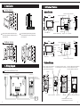
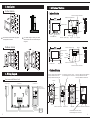
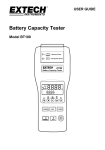
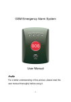
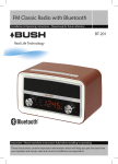
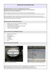
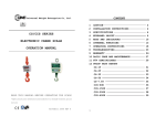
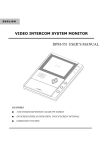
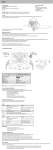
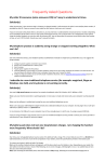
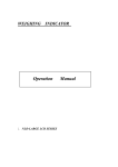
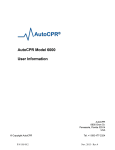
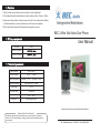
5. Cautions
1) Don't put the camera station under sunshine or other bright light.
2) The standard height of installation of outdoor station is from 145cm to 160cm.
3) Keep the outdoor station 3 meters aways from the indoor station when testing
before installation, in case of interferences in the volume of speaker.
4) Don't open the machine until the professional engineer comes.
BEC 2-Wire Villa Video Door Phone
6. Wiring requipments
User Manual
Distance
Cable
Distance <50meters
Distance >50meters
7. Technical parameters
Input Voltage
Output Voltage
Power Consumption
AC100~240V
DC15V
Standby : ≤1W
1500mA
Working: ≤10W
Cable requirements
2pin Wires, RVV2*0.5mm
Video Signal
1VP-P
Intercom time
60 seconds
Working Temperature
-20C ~ +60C
Illumination
3meters night vision
Please read this user manual carefully before installation
Standard Video Door Phone Kit
A standard video door phone includes: one outdoor station, one indoor
station, one 15V power adaptor, a bag of screws, terminal cables and one
user manual.
7
BEC - Williamsville New York - 716-689-0871 - Toll Free 888-556-3998
One to one with Electromagnetic Lock
15V power supply
Indoor station
Outdoor station
Electromagnetic Lock
contact pin mode (P2 connected)
Products Profile
A standard video door phone is made of one outdoor station
and one indoor station, connected by 2-4 wires, featured with
non-polarized audio & video transmission, HD display,
premium audio clarity, excellent stability, easy DIY installation
for the villa, single house, residential and commercial
buildings. This video door phone is expandable to “one outdoor
station with three indoor stations mostly”.
Door switch
Connect with door switch
(Normally open))
Adjust lock delay time
5 seconds or 10 seconds
Electromagnetic Lock
15V power supply
Lock delay controller
One to three with Electric Lock
15V power supply
Main Features:
1)
2)
3)
4)
5)
HD D/N camera & HD display;
RFID access control
Internal intercoms between monitors
9 ringtones
Alarm & monitor
15V power supply
15V power supply
Electric Lock
contact pin mode
(P1, P3,P4 connected)
Electric Lock
1
6
3. Installation
1. All buttons' features
Indoor station
Indoor Station
Socket for the second indoor station
9.5 in
Socket for the outdoor station
1 in
Speaker
6.25 in
7inch TFT screen
6.25 in
Volume
Monitor
All monitors are surface-mounted. So to put
the mounting bracket on the wall firstly will fix
the monitor well.
Unlock
Talk
Internal Call / Alarm
The standard height of installing the outdoor
station should be from 145cm to 160cm away
from the ground.
Microphone
Socket for the power supply
8.5 in
Outdoor station
Ringtone
Color
Socket for the power supply
Brightness
.75 in
Speaker
Internal Call / Alarm
Monitor
5.5 in
Unlock
Talk
Microphone
7inch TFT screen
Ringtone
Volume
Color
5.5 in
Brightness
Socket for the outdoor station
Socket for the second indoor station
Outdoor Station
4. Wiring diagram
Connect Jp1: Reset controller’s password
Connect Jp2: Delete all users’ cards
Connect Jp3: Make a new master card
For electric lock: connect P1, P3, P4
For electromagnetic lock: connect P2
Connect Jp1: Reset controller’s password
Connect Jp2: Delete all users’ cards
Connect Jp3: Make a new master card
One to one with Electric Lock
Camera
15V power supply
Indoor station
3.75"
Outdoor station
Electric Lock
contact pin mode
(P1, P3,P4 connected)
5.12 in
Microphone
Camera
Speaker
Microphone
6.9 in
ID card
7.7 in
Call button
ID card
Call button
Speaker
Socket for indoor station
Electric Lock
5
Socket for lock
Name plate
Socket for indoor station Socket for lock
For electric lock: connect P1, P3, P4
For electromagnetic lock: connect P2
2
2. Operation instructions
Intercom
1 ) C all : Once the visitor pushes the Call button, it will light up the monitor
ringing, and image of visitor will be shown in the monitor.
2 ) Talk : to answer the call from the outdoor station by pushing Talk/Intercom
button will establish the conversation between the outdoor station and indoor
station, to push Talk button again will hang off . If there is no one answering, the
monitor will be closed after 45 seconds. If the time of conversation is over 45
seconds, the monitor will hang off automatically, but to push Monitor and Call
button again will extend the conversation.
3 ) Alarm/ Unlock : Under conversation, to push Unlock button will open the door.
To keep pushing Alarm button will hear the Warning ring from the outdoor station
that is to scare the stranger away.
4 ) Monitor: Under standby, push Monitor button will see what happened
outside, and push Monitor button again will exit.
5 ) Internal call : Under standby, push Internal call button on the indoor station and
you will hear the intercom tone , then push Talk button to talk to each other.
6 ) Set the ringtone: First under standby, push Talk button for 3 seconds to
enter "the state" of music playing, and then to push Alarm button for 0.5 second at
the same time to play one ringtone, (one by one playing), finally, keep pressing Talk
button for 3 seconds to set your favorite ringtone and exit.
User Instructions of RFID Access Control.
This RFID Access module can save 2720 User cards / fobs and support quick
reading, changing Master card, adding User cards, deleting active user
cards, more convinience and reliable.What's more, there is a professional
RFID controller for better operation, and further needs has to be noted
additionally.
1 ) Make a master card: First, cut off the power of the outdoor
station, second, connect JP2 with power, then sound will be heard every
1.5second,now to swipe new ID card will hear a long beep, that means new
master card has been made,finally to take off JP2 will exit.
2 ) Delete all user cards: First, cut off the power of the outdoor
station , then to connect JP3 with power , now a long beep will be heard ,
that means all user cards has been deleted , finally to take off JP3 will
exit .
3
3 ) Initial Admin Password : Firstly to cut off the power of the outdoor
station , then to connect JP1 with power , now a long beep wll be heard
that means Admin password has been intial as 1234 , finally to take off
JP1 will exit .
4 ) Add more user ID card:
Under standby, firstly to swipe the Master card will come to the state of adding
more user cards, then to swipe the new ID card will hear a Dee beep that means
this new user cards has been activated, finally to swipe the Master card again
will exit and back to standby mode. What's more, 2720pcs user ID card can be
activated by one master card mostly, if there is a long beep at 6 times, that
means the capacity of user card is full.
5) Open the door by ID user card:
Under standby, to swipe the active access ID user card on the access window
will open the door, if the User card is not activated by the Master card, then the
door can not be open and Dee beep will be heard at 3 times.
6) Add more user card by RFID Controller : Under standby, firstly to push * 1234
will hear a long beep, secondly to push * 2 will hear another long beep at every
1.5seconds that means it's time to add more user cards, Finally to push * EXIT
will exit. P.S to swipe new user cards requires to add one by one, and a long beep
will be hear after adding one user card.
7) Delete some user cards by RFID controller: Under standby, firstly to push *
1234 will hear a long beep, secondly to push * 2 will hear another long beep at
every 1.5seconds that means it's time to delete user cards, finally to push * EXIT
will exit.. P.S: to delete the active user cards will hear a long beep, if the user
card is not active, then a long beep will be heard at 3 times.
8) Delete the user cards by serial numbers on the controller: Under standby,
firstly to push *1234 will hear a long beep, secondly to push * 5 will hear another
long beep, then to input 10digits serial number and # will hear a long beep that
means this user card has been deleted, finally to push * EXIT will exit. If the
serial number is wrong, then a long been will be heard at 3 times, so each serial
number of the user card has to be recorded at the beginning.
9) Delete all user cards by RFID controller : Under standby, firstly to push *1234
will hear a long beep, secondly to push * 6 will hear another long beep, then to
push 1 2 # will stop the long beep that means all user cards has been deleted,
finally to push * EXIT will exit.
10) Change Admin Password: Under standby, firstly to push *1234 will hear a
long beep, secondly to push * 1 will hear another long beep, then to input 4 digits
password, finally to push * EXIT will exit.
4
2. Operation instructions
Intercom
1 ) C all : Once the visitor pushes the Call button, it will light up the monitor
ringing, and image of visitor will be shown in the monitor.
2 ) Talk : to answer the call from the outdoor station by pushing Talk/Intercom
button will establish the conversation between the outdoor station and indoor
station, to push Talk button again will hang off . If there is no one answering, the
monitor will be closed after 45 seconds. If the time of conversation is over 45
seconds, the monitor will hang off automatically, but to push Monitor and Call
button again will extend the conversation.
3 ) Alarm/ Unlock : Under conversation, to push Unlock button will open the door.
To keep pushing Alarm button will hear the Warning ring from the outdoor station
that is to scare the stranger away.
4 ) Monitor: Under standby, to push Monitor button will see what happened
outside, and to push Monitor button again will exit.
5 ) Internal call : Under standby, to push Internal call button on the indoor station
will hear the sound Dudu, then to push Talk button will talk to each other.
6 ) Set the ringtone: Firstly, under standby, to keep pushing Talk button for 3
seconds comes to the states of music playing, and then to push Alarm button for
0.5 second at one time will play one ringtone, one by one playing, finally to keep
pressing Talk button for 3 seconds will fix your favourite ringtone and exit.
User Instructions of RFID Access Control.
This RFID Access module can save 2720pcs User cards and support
quick reading , changing Master card , adding User cards , deleting active
user cards , more convinience and reliable . What's more , there is a
professional RFID controller for better operation , and further needs has
to be noted additionally .
1 ) Make a master card : Firstly to cut off the power of the outdoor
station , secondly to connect JP2 with power , then sound will be heard
every 1 . 5second , now to swipe new ID card will hear a long beep , that
means new master card has been made , finally to take off JP2 will exit .
2 ) Delete all user cards : Firstly to cut off the power of the outdoor
station , then to connect JP3 with power , now a long beep will be heard ,
that means all user cards has been deleted , finally to take off JP3 will
exit .
3
3) Initial Admin Password: First to cut off the power of the outdoor station,
then to connect JP1 with power, now a long beep wll be heard that means
Admin password has been intial as 1234, finally to take off JP1 will exit.
4 ) Add more user ID card:
Under standby, first swipe the Master card will come to the state of adding more user
cards, then to swipe the new ID card will hear a beep that means this new user cards
has been activated, finally swipe the Master card again will exit and back to standby
mode. Also, 2720 user ID card can be activated by one master card.
5) Open the door by ID user card:
Under standby, swipe the active access ID user card on the access window will
open the door, if the User card is not activated by the Master card, then the door can
not be open and a beep will be heard 3 times.
6) Add more user card by RFID Controller : Under standby, first, push * 1234
will hear a long beep, second, push * 2 and you will hear another long beep at every
1.5 seconds. That means it's time to add more user cards, Finally push * EXIT will exit.
P.S to swipe new user cards requires to add one by one, and a long beep will be hear
after adding one user card.
7) Delete some user cards by RFID Remote control: Under standby, firstly to push *
1234 will hear a long beep, secondly to push * 2 will hear another long beep at every
1.5 seconds. That means it's time to delete user cards, finally to push * EXIT will exit..
P.S: to delete the active user cards will hear a long beep, if the user card is not active,
then a long beep will be heard at 3 times.
8) Delete the user cards by serial numbers on the controller: Under standby,
firstly push *1234 will hear a long beep, second, push * 5 and you will hear another
long beep, then input the 10 digits serial number and # will hear a long beep that
means this user card has been deleted, finally to push * EXIT will exit. If the serial
number is wrong, then a long been will be heard at 3 times, so each serial number of
the user card has to be recorded at the beginning.
9) Delete all user cards by RFID controller : Under standby, first, push *1234
will hear a long beep, second, push * 6 will hear another long beep, then to push 1
2 # will stop the long beep that means all user cards has been deleted, finally push *
EXIT will exit.
10) Change Admin Password: Under standby, first, push *1234 will hear a
long beep, second, push * 1 will hear another long beep, then to input 4 digits
password, finally to push * EXIT will exit.
4
3. Installation
1. All buttons' features
Indoor station
Indoor Station
Socket for the second indoor station
Socket for the outdoor station
Speaker
7inch TFT screen
Volume
Monitor
All monitors are surface-mounted. Simply put the
mounting bracket on the wall.
The standard height for installing the outdoor
station should be from 4.75ft to 5.5ft away from
the ground.
Unlock
Talk
Internal Call / Alarm
Microphone
Socket for the power supply
Outdoor station
Ringtone
Color
Socket for the power supply
Brightness
Speaker
Internal Call / Alarm
Monitor
Unlock
Talk
Microphone
7inch TFT screen
Ringtone
Volume
Color
Brightness
Socket for the outdoor station
Socket for the second indoor station
Outdoor Station
4. Wiring diagram
Connect Jp1: Reset controller’s password
Connect Jp2: Delete all users’ cards
Connect Jp3: Make a new master card
For electric lock: connect P1, P3, P4
For electromagnetic lock: connect P2
Connect Jp1: Reset controller’s password
Connect Jp2: Delete all users’ cards
Connect Jp3: Make a new master card
One to one with Electric Lock
Camera
15V power supply
Indoor station
Outdoor station
Electric Lock
contact pin mode
(P1, P3,P4 connected)
Microphone
Camera
Speaker
Microphone
ID card
Call button
ID card
Call button
Speaker
Socket for indoor station
Electric Lock
5
Socket for lock
Name plate
Socket for indoor station Socket for lock
For electric lock: connect P1, P3, P4
For electromagnetic lock: connect P2
2
One to one with Electromagnetic Lock
15V power supply
Indoor station
Outdoor station
Electromagnetic Lock
contact pin mode (P2 connected)
Products Profile
A standard video door phone is made of one outdoor
station and one indoor station, connected by 2pin wires,
featured with non-polarized audio & video transmission,
HD display, premium audio clarity, excellent stability,
easy DIY installation for the villa, single house,
residential and commercial buildings. Especially, this
video door phone is expandable to “one outdoor station
with three indoor stations mostly”.
Door switch
Connect with door switch
(Normally open))
Adjust lock delay time
5 seconds or 10 seconds
Electromagnetic Lock
15V power supply
Lock delay controller
One to three with Electric Lock
15V power supply
Main Features:
1)
2)
3)
4)
5)
HD D/N camera & HD display;
RFID access control
Internal intercoms between monitors
9 ringtones
Alarm & monitor
15V power supply
15V power supply
Electric Lock
contact pin mode
(P1, P3,P4 connected)
Electric Lock
1
6
5. Cautions
1. All buttons' features
1) Don't put the camera station under sunshine or other bright light.
2) The standard height of installation of outdoor station is from 4.75 ft to 5.5 ft
3) Keep the outdoor station 10 feet or 3 meters aways from the indoor station when
testing before installation, in case of interferences in the volume of speaker.
2-Wire Villa Video Door Phone
6. Wiring requipments
User Manual
Distance
Cable
2 or 4 Wire - 20 awg
2 or 4 Wire - 18 awg
Distance < 164 feet
Distance > 164 feet
7. Technical parameters
Input Voltage
Output Voltage
Power Consumption
Cable requirements
Video Signal
AC100~240V
DC15V
1500mA
Standby : ≤1W
Working: ≤10W
2 or 4 Wires, 18 - 20 awg
1 VP-P
Intercom time
60 seconds
Working Temperature
-5F to 130F or -20C ~ +60C
Illumination
10 feet - 3 meters night vision
BEC Standard Video Door Phone Kit
A standard video door phone includes: one outdoor station, one indoor
station, one 15V power adaptor, a bag of screws, terminal cables and one
user manual.
7
Please read this user manual carefully before installation