1
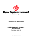
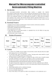
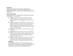
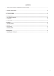
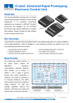
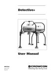
Gradient Pumping for Pressure, Flow, and Concentration Modes Syringe Pump Technical Bulletin TB24 With Teledyne Isco Syringe Pumps Overview Connecting the System Gradient pumping is used in applications requiring time-controlled or rate-controlled delivery of a specific volume at a set flow rate or pressure, or a two-pump flow concentration. All Teledyne Isco syringe pump models can be used in gradient mode. The model 65D requires special hardware for this. Call the factory for complete information. You can program the controller to increase or decrease pressure or flow during different steps within a single program by entering a specific value at the beginning and end of each step. The syringe pump has two ports at the top of the cylinder. One port is used as the inlet for filling the pump, and the other as the outlet (either port may be used as inlet or outlet). Inlet and outlet connections to each pump must be made identically. Standard plumbing connections vary between pump models. See Table 3 below for standard port information. When making fluid connections that use ferrules, be sure to use the ferrules supplied for that pump by Teledyne Isco. Push the tubing completely into the connector and finger-tighten. Then tighten with a wrench to clamp the ferrules onto the tubing. DANGER Table 3: Standard Port Connections RISK OF INJURY. THE PRESSURE PRODUCED COULD BE 700 BAR. PLEASE UTILIZE APPROPRIATE TUBING AND CONNECTIONS NOTED IN YOUR USER MANUAL. Tools and Parts for Single Pump System Open-end wrenches: 1/4", 5/16", 7/16", 3/8" Manual Refill Valve Kit - see Table 1 Manual Outlet Valve Kit - see Table 2 1000D 500D 65DM, 100DM/DX, 260D 65D 68-1247-117 68-1247-083 68-1247-077 68-1247-127 Part Number 1000D 500D 65DM, 100DM/DX, 260D 65D 68-1247-118 68-1247-082 68-1247-078 68-1247-126 1/8" Valco 500D 1/8" NPT NUT 5-16 - 24 1/2 TURN PAST FINGER-TIGHT FERRULE NUT 5-16 - 24 3/4 TURN PAST FINGER-TIGHT FRONT FERRULE 1000D 1/4" NPT 65D 1 FRONT FERRULE /4" F250C NUT 7-16 - 20 1-1/4 TURN PAST FINGER-TIGHT Call Teledyne Isco. Note Pump models 260D, 100DM/DX, and 65DM have a direct connection, as shown in Figures 1 and 2 on the following page. Valve kits for other models include male adapter fittings. A gradient pumping system includes high-pressure, two-way valves that connect the pump inlets to fluid reservoirs, and the pump outlets to the gradient mixer (dual pump system) or Two-Way other apparatus (single pump Valve part system). Each refill kit and outlet #209-0098-05 valve package contains one two-way valve; the gradient package contains two. The kits contain all tubing and hardware necessary for valve installation. Following installation, the tubing connections must be tested for leaks before any program is run. Table 2: Manual Outlet Valve Kits Pump Model 65DM, 100DM/DX, 260D Swaging Detail BACK FERRULE Table 1: Manual Refill Valve Kits Part Number Ports BACK FERRULE Tools and Parts for Dual Pump System Open-end wrenches: 1/4", 5/16", 7/16", 3/8" Manual Refill Valve Kit see Table 1 (two kits required) Gradient Mixer Package - part #68-1247-080 Pump Model Pump 1 Syringe Pump Technical Bulletin TB24 If a leak is found, tighten the connection slightly. If the leak persists, swage the connection again with a new ferrule. Refer to Technical Bulletin TB05 Field Verification Procedures for leak test procedures. Outlet Connections Kit components and connections are shown in Figure 2. 1. Mount the two-way outlet valve on the side of the pump housing opposite the refill valve, with the spacer block and screws provided. 2. Connect the pre-bent SST tubing between one port of the valve and the pump outlet. Use the nut and ferrule to connect the tubing at the outlet and the valve fittings to connect the tubing at the valve. Inlet Connections Kit components and connections are shown in Figure 1 on the following page. 1. Mount the inlet valve on the pump housing with the spacer block and screws provided. 2. Connect the pre-bent SST tubing from one port of the valve to the pump inlet. Use the nut and ferrule to connect the tubing at the inlet and the valve fittings to connect the tubing at the valve. 3. Connect the PTFE refill tubing (with the filter) to the other port of the valve, using the nuts and ferrules supplied. 3. Connect the 5.1 cm length of 18" tubing to the other port of the valve, using the valve fittings. 4. Connect the 18" side of the reducing union to the tubing. 5. Connect the 116" side of the reducing union to the 1.5 m length of 116" tubing. (This tubing may be cut to an appropriate length.) Note When connecting to pressurized sources in supercritical fluid applications, use the stainless steel tubing without a filter. An in-line filter is contained in the CO2 connection package (refer to technical bulletin TB08 CO2 Applications and Technical Notes). nut, ferrule pre-bent SST tubing to system FROM REFILL KIT ASSEMBLY pre-bent SST tubing spacer block spacer block PTFE tubing or stainless steel tubing SST tubing 2-way valve valve filter TO APPARATUS Figure 1: Pump inlet connections Figure 2: Pump outlet connections 2 Syringe Pump Technical Bulletin TB24 1. Connect the 10 cm length of 116" stainless steel tubing to the center port (outlet) of the mixer using the PEEK fittings provided. 2. Connect the other end of the tubing to the Valco valve at the port marked “P” (pump), using a Dual System Gradient Connections Connection of the dual gradient system requires two refill valve kits and the gradient mixer package, as discussed in the overview on page 1. The static mixer has an internal volume of 3.1 µl and pressure rating of 413.7 bar, and is supplied with PEEK Fingertight III fittings for connection to the 1/16" tubing in the kit. Valco 116" nut and ferrule. 3. Connect the two in-line filters, oriented with flow toward the check valves (indicated by the arrow on the housing), one filter to each piece of 116" stainless steel tubing outlet from each pump. 4. Using the PEEK fittings, connect the 45.7 cm Note The static mixer can be replaced by a user-supplied dynamic mixer. lengths of 116" stainless steel tubing to each inlet port on the mixer. Connect the other ends to the outlet fittings of the check valve assemblies. 5. Connect the two check valve inlets to the outlets of the in-line filters with the 12.7 cm lengths of tubing. 6. Press the check valves into the clips on the stand, as shown below, oriented with flow in the upward direction (indicated by the arrow on the housing). Solvents are fed from each pump through the in-line filters and check valves, and into the static mixer, where they are mixed and fed into your system apparatus. Kit components and connections are shown in Figures 3 and 4. OUTLET 1/8” OD X 0.069”ID SST TUBING INLET OUTLET D C (from refill kit) INLET B VALVE A (from refill kit) 1/8” OD X 0.085”ID PTFE TUBING 1/8” TO 1/16” REDUCER flow FILL RESERVOIR 10µ FILTER flow INLINE FILTER Figure 3: Dual gradient system connections Inlet valves (A & C) are from refill valve kit) 3 MIXER (to apparatus) CHECK VALVES 1/16” OD X 0.020”ID SST TUBING VALVE STAND Syringe Pump Technical Bulletin TB24 Close-up of mixer assembly Close-up of valve stand Close-up of in-line filter flow flo w The home screen will appear, with either PG Figure 4: Dual gradient connections: Detail (Pressure Gradient) or FG (Flow Gradient) in the upper left corner. Single-Pump Gradient Programming PGa A single-pump gradient program is based on either pressure or flow, and controlled by either time duration (in minutes) or rate of change (units per minute). The controller’s memory can contain a total of up to 200 steps. One program can contain from 1 to 200 steps. When operating in gradient mode, any connected pumps not used for gradient are inoperable. STOPPED FILE:1 00:00:00 /MIN FINAL: PSI PROGRAM EDIT REVIEW OPTION 0.000mL/MIN 2PSI 013.28mL 2. Press PROGRAM (A). 3. At the prompt, enter a file number between 1 and 99. This is the file name of your program, and can be the name of a new program you are creating, or a stored program you want to edit or run. Press ENTER. 1. To access the gradient programming menus, press PRGM GRAD, and follow the sequence shown below. Note If a selected stored program is in a different mode than that of the controller selected in Step 1, a brief notification will appear, displaying the controller’s mode and the file’s mode. If you attempt to run the program without changing the mode of either it or the controller, the program will not run, and the same message will be displayed. 1. TWO PUMP CONCENTRATION GRADIENT 2. ONE PUMP PRESSURE GRADIENT 3. ONE PUMP FLOW PROGRAMMING CONTINUE 4. To enter the flow rate for this program, either press FLOWRATE (A) and use the number keys and Enter, or for maximum possible flow, simply press MAX (C). RETURN or (PRESSURE) ENTER FLOWRATE 0.00000 (FLOW) XX.00000 (CONTINUE) FLOWRATE 4 PREVIOUS MAX Syringe Pump Technical Bulletin TB24 Dual Pump Concentration Gradient Programming 5. To proceed to the programming screen, press STEP FWD (B). The programming screen will appear, with the file number and step number at the top of the screen. PGa FILE# 1 1. INIT = 0PSI STEP# 1 3. RATE = Two-pump concentration gradients enable proportionate use of two different fluids that combine at the mixer (refer to Figures 3 and 4). This type of pumping uses flow mode (FG) only. A single-pump gradient program is based on either pressure or flow, and controlled by either time duration (in minutes) or rate of change (units per minute). The controller’s memory can contain a total of up to 200 steps. One program can contain from 1 to 200 steps. When operating in gradient mode, any connected pumps not used for gradient are inoperable. STORE TO EXIT 0:00PSI/MIN 2. FINAL = 0PSI 4. DURATION = 1.0MIN INSERT DELETE or FGa FILE# 1 STEP# 1 STORE TO EXIT 1. INIT% = 3. RATE = 0.00%/MIN 2. FIN% = 4. DURATION = 1.0MIN INSERT DELETE 1. To access the gradient programming menus, press PRGM GRAD, and follow the sequence shown below. 6. To set the initial pressure or flow for this step, press INIT (1) to activate this parameter. Use the number keys to enter the desired value, then press ENTER to save it. 7. To set the final pressure or flow for this step, press FINAL (2) to activate this parameter. User the number keys to enter the desired value, then press ENTER to save it. 8. Set either the desired RATE (3) of change or DURATION (4) in minutes. Once one value has been set and saved, the other will automatically appear. 1. TWO PUMP CONCENTRATION GRADIENT 2. ONE PUMP PRESSURE GRADIENT 3. ONE PUMP FLOW PROGRAMMING CONTINUE RETURN Note DURATION in minutes can have a resolution of 0.1, with a maximum of 9,999 minutes per step. 9. If you want to add another step to the file program, press INSERT (C). The step number will increase by one, and the default initial value will be the final value entered for the previous step. Edit as desired. 10. When programming is complete, press the STORE key to save the file and return to the home screen. 11. To start the program, press RUN two times. DUAL SYSTEM GRADIENT (FLOW) (CONTINUE) The home screen will appear, with FG (Flow Gradient) in the upper left corner. FGa 0.000mL/MIN STOPPED Note When a gradient run is started, digital output 8 of the controller ACCESSORY connector will toggle from high to low (open to closed) for one second. PROGRAM 2PSI 013.28mL FILE:1 00:00:00 FINAL: %B EDIT REVIEW OPTION 2. Press PROGRAM (A). 3. At the prompt, enter a file number between 1 and 99. This is the file name of your program, and can be the name of a new program you are creating, or a stored program you want to edit or run. Press ENTER. Note that an entire gradient program can be removed only by deleting each of its steps one at a time, as discussed in Review, Revise, & Hold Options. When the last remaining step is deleted, the entire file is removed. 5 Syringe Pump Technical Bulletin TB24 Note Note If a selected stored program is in a different mode than that of the controller selected in Step 1, a brief notification will appear, displaying the controller’s mode and the file’s mode. If you attempt to run the program without changing the mode of either it or the controller, the program will not run, and the same message will be displayed. DURATION in minutes can have a resolution of 0.1, with a maximum of 9,999 minutes per step. 9. If you want to add another step to the file program, press INSERT (C). The step number will increase by one, and the default initial value will be the final value entered for the previous step. Edit as desired. 10. When programming is complete, press the STORE key to save the file and return to the home screen. 11. To start the program, press RUN two times. 4. To enter the flow rate for this program, either press FLOWRATE (A) and use the number keys and Enter, or for maximum possible flow, simply press MAX (C). Note When a gradient run is started, digital output 8 of the controller ACCESSORY connector will toggle from high to low (open to closed) for one second. ENTER FLOWRATE 0.00000 FLOWRATE XX.00000 PREVIOUS The flow rates and ramp rate for Pump A in each step will be in direct opposite proportion to the values set for Pump B (INIT%B, FIN%B, and RATE). MAX 5. To proceed to the programming screen, press STEP FWD (B). The programming screen will appear, with the file number and step number at the top of the screen. FGa FILE# 1 STEP# 1 Note that an entire gradient program can be removed only by deleting each of its steps one at a time, as discussed in the next section, Review, Revise, & Hold Options. When the last remaining step is deleted, the entire file is removed. STORE TO EXIT 1. INIT% = 3. RATE = 0.00%/MIN 2. FIN% = 4. DURATION = 1.0MIN INSERT DELETE 6. To set the initial pressure or flow for this step, press INIT (1) to activate this parameter. Use the number keys to enter the desired value, then press ENTER to save it. 7. To set the final pressure or flow for this step, press FINAL (2) to activate this parameter. User the number keys to enter the desired value, then press ENTER to save it. 8. Set either the desired RATE (3) of change or DURATION (4) in minutes. Once one value has been set and saved, the other will automatically appear. 6 Syringe Pump Technical Bulletin TB24 Review, Revise, & Hold Options Program Conclusion While in the programming menu, you can also: Delete — To delete the current step, press DELETE (D). A deleted step cannot be recovered. Used repeatedly, this command can be used to delete an entire file. Review — To review existing program steps, press STEP BACK (A) or STEP FWD (B). Add New — To add a new step between two existing steps, navigate through the program to the step just before your addition. Press INSERT (C) and program the new step. Note that the initial value of the next step will default to the final value of the new step, and may need to be edited if a different initial value is needed. While Running — A gradient program can be reviewed or edited while it is running. Simply press EDIT (B) or REVIEW (C) to begin. If a new step duration is shorter than the elapsed time for that step, the program will proceed to the next step. If the total flow rate is changed, the program will immediately start using the new rate. To return to the run screen, press RETURN (D). Hold — You can hold a running gradient in its current state while retrieving a different program file to run in its place. Press Hold and then Recall to access the new program. This feature is used mainly in applications where it is necessary to keep the system pressurized during method changes. External Start — When a gradient program is in Hold mode, a momentary low on digital input 2 of the controller ACCESSORY connector will start the program. When a gradient program reaches the end, there are four selectable actions the system can then perform: ● Hold the final value (example below) ● Stop after the final step ● Return to the initial value and hold it ● Return to the initial value and repeat the program While the system is in gradient mode, these options can be edited at any point before or after gradient programming, and while a gradient is running. To access the options menu, from the home screen, press OPTIONS (D). GRADIENT ACTION=HOLD FINAL VALUE NEXT_ACTION PREVIOUS To scroll through the four options, press NEXT_ACTION (A). When you have reached the desired option, press PREVIOUS (D) to save and exit. Teledyne Isco P.O. Box 82531, Lincoln, Nebraska, 68501 USA Toll-free: (800) 775-2965 • Phone: (402) 464-0231 • Fax: (402) 465-3001 E-mail: [email protected] Teledyne Isco is continually improving its products and reserves the right to change product specifications, replacement parts, schematics, and instructions without notice.