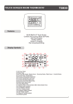
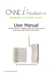
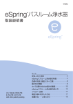
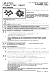
1
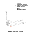
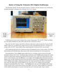
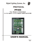
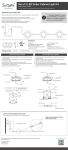
Application NOTE
3 Simple Step PalmLUX Setup
AN257
General
PalmLUXf range of lighting controls was designed with both user and installer in mind. All PalmLUXf devices are fitted with onboard DIL switches, that facilitate simple installation and commissioning. There is no need for software tools or proprietary
configuration devices. Anyone can fully configure basic PalmLUXf system with only terminal screw driver and product user manual.
3 SIMPLE STEP
PalmLUX SETUP
SYSTEM FULLY WIRED
BY QUALIFIED ELECTRICIAN
TURN SYSTEM
POWER OFF
SET ACTUATOR (DIMMER)
CHANNEL ADDRESSES
SET ACTUATOR (DIMMER) ZONE
ADDRESSES (OPTIONAL**)
SET KEYPAD ZONE
ADDRESSES (OPTIONAL**)
TURN SYSTEM POWER ON
Wait System Boot Up Complete
SYSTEM READY
Before PalmLUXf system can be used, all actuators (dimmers, relays, etc.) have to be given unique channel addresses. Once
channel address has been set, each actuator will operate in “broadcast mode”. The same is true for all keypads, which are as factory
default configured to send commands in “broadcast”. This way each keypad will control all devices on PalmLUXf network.
Therefore, to get system up and running, the only pre-requisit is to set actuator channel addresses. The system can then be used in
broadcast unit detailed commissioning is carried out.
AN257
D608
Application
User Guide
NOTE
Doc.D608-01
Doc.AN257-01
PAGE 01
PHASELINER LTD
17 Hervey Court., 20 Surrey Lane, London, SW113PT UK Tel.02072231069 Fax.02078019131 WEB: www.phaseliner.co.uk EMAIL: [email protected]
Application NOTE
3 Simple Step PalmLUX Setup
AN257
STEP 01 - Set Actuator Channel Addresses
First step would be to configure actuator channel addresses. Under actuators, we consider dimmers, relays, blind motor controllers,
projector screen controllers, 1-10V ballast controllers, DSI ballast controllers, LED drivers and other devices designed to control
some type of load.
All channel addresses on PalmLUXf network must be unique and can be set via on-board address DIL switch. Each device user
guide contains address table indicating settings required to assign a device channel address. The settings are the same throughout
the range. When adjusting DIL switches, device power must be safely OFF. Also ensure that all switches are fully engaged.
Channel DIL switch can be found on each device at the bottom of the unit, once terminal guide is removed. Please refer to the
diagram bellow where D502 dimmer is shown. For details on DIL switch locations please refer to particular device documentation.
PalmLUXf device feature “Address Conflict Resolution Algorithm” that can be used to check for existence of duplicated channel
addresses. This algorithm is instigated by the device with channel address 1 after power up. In case there is no address 1 in the
system, the algorithm will not be active. The feature can also be disabled via PalmLUXf palm computer utility. For details on
“Address Conflict Resolution Algorithm” please refer to AN258 application note.
Power
Terminal Block
Lift terminal guard to
access DIL switches
and terminals
N-L-D
Right-hand DIL Switch:
Zone 6-Way
Left-hand DIL Switch:
Address 4-Way
Status LED
PHASELINER
P
PalmLUX
almLUX
D502
Temperature
LED
Status
Temp
500W PalmLUX
A-Sc-B Digital Dimmer
ZONE
DIL Switch
Data (DALI)
Terminal Block
Address
DIL Setting
Address
DIL Setting
Channel
Address
DIL Switch
Address
DIL Setting
1
0
0
0
0
0
1
0
1
0
1
0
1
22
1
0
1
0
1
0
43
0
1
0
0
0
0
2
0
1
0
1
1
0
23
1
0
1
0
1
1
44
0
0
1
0
0
0
3
0
1
0
1
1
1
24
1
0
1
1
0
0
45
0
0
0
1
0
0
4
0
1
1
0
0
0
25
1
0
1
1
0
1
46
0
0
0
0
1
0
5
0
1
1
0
0
1
26
1
0
1
1
1
0
47
0
0
0
0
0
1
6
0
1
1
0
1
0
27
1
0
1
1
1
1
48
0
0
0
0
0
0
7
0
1
1
0
1
1
28
1
1
0
0
0
0
49
0
0
0
0
1
1
8
0
1
1
1
0
0
29
1
1
0
0
0
1
50
0
0
0
1
0
1
9
0
1
1
1
0
1
30
1
1
0
0
1
0
51
0
0
1
0
0
1
10
0
1
1
1
1
0
31
1
1
0
0
1
1
52
0
1
0
0
0
1
11
0
1
1
1
1
1
32
1
1
0
1
0
0
53
1
0
0
0
0
1
12
0
0
0
1
1
0
33
1
1
0
1
0
1
54
0
0
1
1
0
0
13
0
0
1
0
1
1
34
1
1
0
1
1
0
55
0
0
1
1
0
1
14
1
0
0
0
1
0
35
1
1
0
1
1
1
56
0
0
1
1
1
0
15
1
0
0
0
1
1
36
1
1
1
0
0
0
57
0
0
1
1
1
1
16
1
0
0
1
0
0
37
1
1
1
0
0
1
58
0
0
0
1
1
1
17
1
0
0
1
0
1
38
1
1
1
0
1
0
59
0
0
1
0
1
0
18
1
0
0
1
1
0
39
1
1
1
0
1
1
60
0
1
0
0
1
0
19
1
0
0
1
1
1
40
1
1
1
1
0
0
61
0
1
0
0
1
1
20
1
0
1
0
0
0
41
1
1
1
1
0
1
62
0
1
0
1
0
0
21
1
0
1
0
0
1
42
1
1
1
1
1
0
63
1
1
1
1
1
1
64
AN257
D608
Application
User Guide
NOTE
Doc.D608-01
Doc.AN257-01
PAGE 02
01
PHASELINER LTD
17 Hervey Court., 20 Surrey Lane, London, SW113PT UK Tel.02072231069 Fax.02078019131 WEB: www.phaseliner.co.uk EMAIL: [email protected]
Application NOTE
3 Simple Step PalmLUX Setup
AN257
STEP 02 - Set Actuator ZONE Addresses
Second step would be to set actuator zone addresses, in the same manner as for the channel address, but with the difference that
these now can be repeated. Devices can also keep the default setting, “broadcast”.
Devices can also be members of several zones at the same time. There are three pre-program settings that will cater for most
projects, as listed: 1-2, 1-2-3, 3-4, 2-3-4 and 1-2-10. For detailed settings, please consult device user guide.
Full flexibility of 16 zones in any combination is available via PalmLUXf configuration utility for palm computer. For details please
consult PalmLUXf documentation.
DIL : 0000
BROADCAST
ON
DIL: 1000
ZONE: 01
ON
DIL: 0100
ZONE: 02
ON
DIL: 0010
ZONE: 03
ON
2 3 4
1
DIL: 1001
ZONE: 07
2 3 4
2 3 4
DIL: 1011
ZONE: 3+4
ON
2 3 4
1
DIL: 0110
ZONE: 10
2 3 4
DIL: 0111
ZONE: 3+4+5
ON
2 3 4
1
DIL : 1110
ZONE: 1+2
ON
1
1
DIL: 1101
ZONE: 09
ON
DIL: 0011
ZONE: 1+2+3
ON
2 3 4
ON
1
DIL: 1010
ZONE: 06
ON
1
2 3 4
2 3 4
DIL: 0101
ZONE: 08
ON
1
DIL: 1100
ZONE: 05
ON
1
2 3 4
1
2 3 4
ON
1
2 3 4
1
1
1
2 3 4
1
DIL: 0001
ZONE: 04
ON
2 3 4
ON
2 3 4
1
2 3 4
DIL: 1111
ZONE:
1+2+10
STEP 03 - Set Keypad Zone Assignments
Last thing to do would be to assign keypads to zones. This is done by setting zone address switches on wall keypads. Each
PalmLUXf keypad is fitted with zone DIL switch. Here user can select zones 1-10. Further 6 zones are programmable via
PalmLUXf utility. In addition to 10 zones, user can also select two unique settings called “Entrance DOOR” which allows all lights in
the house to be turned on-off from the entrance door, plus “Top of stairs” setting that allows all lights “downstairs” to be turned off from
the “top-of-stairs” switch.
1
V
Remove cover plate to gain
access to DIL switches using
4mm screw driver.
2
V
3
V
4
OFF
V
O
ON
1
Locate plate removal
notch at the bottom rear
edge of the cover plate.
2 3 4
ZONE DIL Switch
AN257
D608
Application
User Guide
NOTE
Doc.D608-01
Doc.AN257-01
PAGE 03
01
PHASELINER LTD
17 Hervey Court., 20 Surrey Lane, London, SW113PT UK Tel.02072231069 Fax.02078019131 WEB: www.phaseliner.co.uk EMAIL: [email protected]
Application NOTE
3 Simple Step PalmLUX Setup
2 3 4
DIL : 0000
BROADCAST (ALL DEVICES)
LED Tell-back: broadcast
2 3 4
DIL: 1000
ZONE: 01
LED Tell-back: Zone 01
2 3 4
DIL: 0100
ZONE: 02
LED Tell-back: Zone 02
2 3 4
DIL: 0010
ZONE: 03
LED Tell-back: Zone 03
2 3 4
DIL: 0001
ZONE: 04
LED Tell-back: Zone 04
2 3 4
DIL: 1100
ZONE: 05
LED Tell-back: Zone 05
2 3 4
DIL: 1010
ZONE: 06
LED Tell-back: Zone 06
2 3 4
DIL: 1001
ZONE: 07
LED Tell-back: Zone 07
2 3 4
DIL: 0101
ZONE: 08
LED Tell-back: Zone 08
2 3 4
DIL: 1101
ZONE: 09
LED Tell-back: Zone 09
2 3 4
DIL: 0110
ZONE: 10
LED Tell-back: Zone 10
2 3 4
DIL : 1110
ZONE: 11
LED Tell-back: Zones 1/2/3
2 3 4
DIL: 0011
ZONE: 11
LED Tell-back: Zones 1/2/3/4
2 3 4
DIL: 1011
ZONE: 11
LED Tell-back: Zones 1/2/3/4/5
ON
1
ON
1
ON
1
ON
1
ON
1
ON
1
ON
1
ON
1
ON
1
ON
1
ON
1
ON
1
ON
1
ON
1
DIL Switch SETTING: 0111
Top of Stairs Config
ON
1
1
2 3 4
KEYPAD ZONE SETTING DIL SWITCH
The DIL switch is situated at the bottom of the PCB, accessable from the front of
the unit once cover plate is removed. Use suitable flat blade screwdriver or
similar tool to adjust the DIL setting. The adjustment must be carried out with
care, as even thought the DIL switch is designed for this operation, excessive
force may irreversibly damage the switch and the unit.
DIL switch setting affects keypad globally, i.e. all switches will accept the same
zone. In case separate zone assignments are required for different buttons, the
feature is available via PalmLUXf programming utility.
ENTRANCE DOOR SETTING
This setting provides convenient way of introducing ALL OFF and ALL ON
functions at the entrance door, or elsewhere in the property. It is achievable
without a need for a programming tool, by simply setting the DIL switch to position
1111. The ALL ON function is actually recall scene 16, hence, it can be used as
any global scene, for instance as security scene, turning on a single lighting
circuit at low in each zone of the property. The buttons assignments are as
follows:
Button 01: Trigger Scene 09 Zone 10
Button 02: Trigger Scene 10 Zone 10
Button 03: Trigger Scene 11 Zone 10
Button 04: Trigger Scene 12 Zone 10
Button 05: Trigger Scene 13 Zone 10
Button 06: Trigger Scene 14 Zone 10
Button 07: Trigger Scene 16 Broadcast
Button 08: Trigger OFF with FADE Broadcast
TOP OF STAIRS SETTING
This setting is designed for top of stairs locations where occupants so often have
need to turn off all lighting downstairs, without having to attend to individual zone
keypads. By programming scene 14 to zero at all actuators (dimmers) operating
at the ground level and setting the top of stairs keypad to 1110, the “ground floor
OFF” function will become available. Note: in order not to affect lighting level
elsewhere all other dimmer should have the scene 14 at “ignore” (factory
default).
Button 01: Trigger Scene 01 Zone 10
Button 02: Trigger Scene 02 Zone 10
Button 03: Trigger Scene 03 Zone 10
Button 04: Trigger Scene 04 Zone 10
Button 05: Trigger Scene 05 Zone 10
Button 06: Trigger Scene 06 Zone 10
Button 07: Trigger Scene 07 Zone 10
Button 08: Trigger Scene 14 Broadcast
LED TELL-BACK
The button LEDs illuminate each time the command assigned to that button and
belonging to the same zone appears on the bus. This commands can be
triggered on the actual keypad or any other keypad on the network.
On certain DIL switch setting the LED tell-back over-lapping is enabled, see
settings 1110/0011/1011. These setting enable listening groups, i.e. LED being
illuminated following the appearance of the relevant command originated from a
several different zones.
NOTE: PalmLUXf lighting network supports up to 16 zones. Addressing
keypads to zones 11-16 is only available via PalmLUXf programming utility.
2 3 4
ON
AN257
DIL Switch SETTING: 1111
Entrance Door Config:
Emulates ALL ON & ALL OFF
3
AN257
D608
Application
User Guide
NOTE
Doc.D608-01
Doc.AN257-01
PAGE 04
01
PHASELINER LTD
17 Hervey Court., 20 Surrey Lane, London, SW113PT UK Tel.02072231069 Fax.02078019131 WEB: www.phaseliner.co.uk EMAIL: [email protected]