1
Basics of Using the Tektronix 3012 Digital Oscilloscope
This document {briefly} describes the basic features of, and how to use the Tektronix 3012 Oscilloscope.
Detailed information is contained in the Tektronix 3012 User’s Manual.
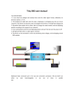
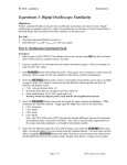
AC Pwr
On/Off
Switch
Ch1 & Ch2
Inputs
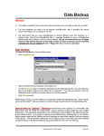
Oscilloscopes are devices used to display time-varying voltage signals. The Tek 3012 ‘Scope can display
two such signals simultaneously (the yellow and blue traces on the above screen).
Plug in the Tek 3012 ‘Scope to the 120Vac wall power, then turn it on by pressing the AC power On/Off
Switch. It takes a few seconds for the ‘Scope to boot up {it has a specialized processor in it}. The power-on
settings of the Tek 3012 ‘Scope default to those selected/operative at the time when it was last used.
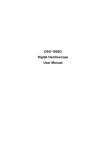
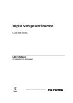
On the right-hand side of the Tek ‘Scope the controls are organized into four vertical columns. The yellow
(blue) buttons on the left-hand side of this section of the ‘Scope select/activate Ch1 (Ch2) respectively.
The knobs/buttons in the Vertical column enables the user to set/adjust various of the Ch1/Ch2 input
parameters/settings of the ‘Scope. Rotating the large round knob in the Vertical column changes the voltage
sensitivity setting of the ‘Scope (for the selected Ch1/Ch2) from 1 mV to 100 V per vertical division on the
above waveform display screen. The Off button in the middle of the Vertical column deletes/deactivates the
display of the currently selected Ch1/Ch2 (yellow/blue button, respectively). The Menu button at the bottom
of the Vertical column displays additional parameters that can be selected from the buttons immediately
below and to the right of the waveform display screen, such as DC or AC coupling of the input signal,
limiting the bandwidth (BW) of the ‘Scope, … The Position knob at the top of the Vertical column simply
sets the location of the 0 Volts reference point on the display screen of the ‘Scope. Explicitly try using each
of these knobs/controls/buttons to see/learn what each does, how it functions and/or what it controls.
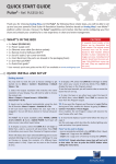
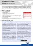
1 The knobs/buttons in the Horizontal column enables the user to set/adjust the time base of the ‘Scope –
i.e. the time units per horizontal division on the display screen of the scope. By rotating the large round knob
in the Horizontal column, the ‘Scope’s time base can be changed in discrete steps ranging from 1 ns to 10 s
per horizontal division of the ‘Scope. The Position knob at the top of the Horizontal column simply sets the
location of the t = 0 horizontal reference point on the display screen of the ‘Scope. Pressing the Delay button
in the Horizontal column calls up a menu that enables the user to delay the selected Ch1/Ch2’s signal,
relative to the time of the ‘Scope’s Trigger (discussed below). Pressing the button with the Magnifying
Glass Icon calls up yet another menu that enables the user to {locally} expand the time base about the trigger
time.
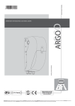
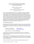
The knobs/buttons in the Trigger column enables the user to trigger the display of the Ch1/Ch2 signals
either from e.g. the rising or falling slope of Ch1 (or Ch2), or e.g. from an external reference signal, or, to
have the ‘Scope automatically trigger on Ch1, Ch2 or the ext. ref. signal. The Menu button at the bottom of
the Trigger column additionally displays these parameters, which can be selected from the buttons
immediately below and to the right of the waveform display screen.
The last/furthest to the right Acquire column has buttons that Run/Stop the display, allow only a Single
Trigger; the Menu button in the Acquire column enables the user to access/select other related features. If
the waveform(s) are too dim/too bright, rotate the Waveform Intensity knob in the Acquire column to
adjust. Pressing the AutoSet button time-irreversibly resets the ‘Scope (essentially) to its factory default
settings, modulo a bit of smarts for figuring out a suitable choice for volts/vertical division and time
units/horizontal division on the ‘Scope’s display screen… this is a very useful button to press if the totality of
the settings on the ‘Scope are so hopelessly screwed up to be able to figure them out in any reasonable
amount of time…
There are many more powerful features associated with the Tek 3012 ‘Scope – the above discussed are
just the basics. The ‘Scope can measure frequencies/periods, voltage amplitudes, as well as more
sophisticated things such as the harmonic content of the waveform(s), via Fast Fourier Transform (FFT)
techniques… It is also possible to readout/waveform capture the ‘Scope’s screen display contents via the
internet… Consult the Tek 3012 ‘Scope User Manual or ask one of the POM Lab TA’s for more information
on using these more advanced measurement capabilities of the Tek 3012 ‘Scope.
2